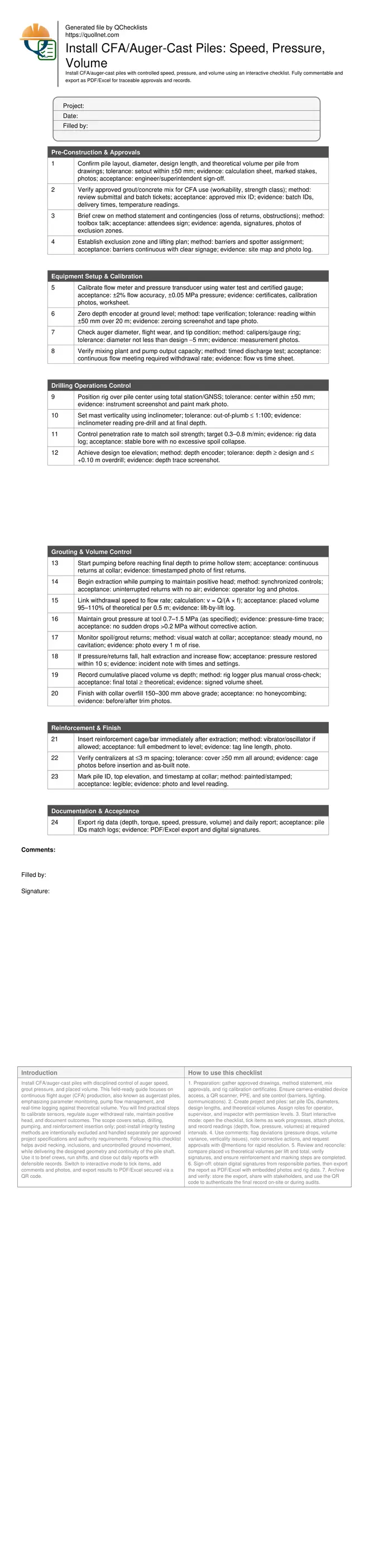
Install CFA/Auger-Cast Piles: Speed, Pressure, Volume
Definition: Install CFA/auger-cast piles by controlling auger speed, grout pressure, and placed volume—an on-site checklist for supervisors, drillers, and inspectors to deliver consistent production piles.
- Calculate theoretical volume and verify placed volume within acceptance limits.
- Control auger penetration and withdrawal rates relative to pump flow.
- Maintain positive grout pressure to prevent voids and soil collapse.
- Interactive, commentable checklist with export and QR code verification.
Install CFA/auger-cast piles with disciplined control of auger speed, grout pressure, and placed volume. This field-ready guide focuses on continuous flight auger (CFA) production, also known as augercast piles, emphasizing parameter monitoring, pump flow management, and real-time logging against theoretical volume. You will find practical steps to calibrate sensors, regulate auger withdrawal rate, maintain positive head, and document outcomes. The scope covers setup, drilling, pumping, and reinforcement insertion only; post-install integrity testing methods are intentionally excluded and handled separately per approved project specifications and authority requirements. Following this checklist helps avoid necking, inclusions, and uncontrolled ground movement, while delivering the designed geometry and continuity of the pile shaft. Use it to brief crews, run shifts, and close out daily reports with defensible records. Switch to interactive mode to tick items, add comments and photos, and export results to PDF/Excel secured via a QR code.
- This checklist standardizes CFA/auger-cast pile installation by aligning auger withdrawal rate with pump flow, maintaining positive grout pressure, and tracking cumulative placed volume against theoretical calculations. Calibrations, acceptance thresholds, and real-time evidence capture minimize defects like necking, inclusions, and ground heave while improving productivity and traceability.
- Interactive online checklist with tick, comment, and export features secured by QR code. It enables photo evidence, rig-data attachments, and instant variance flags so supervisors can resolve pressure drops, flow mismatches, and positional deviations before they create rework. Verified exports streamline approvals and progress reporting for daily pile production.
- The procedure emphasizes sensor verification, mast alignment, collar control, and spoil-return observation, supported by hard tolerances (position, verticality, pressure, and volume). It avoids integrity testing steps, keeping the scope tightly on installation controls and records required for acceptance per approved project specifications and authority requirements.
Pre-Construction & Approvals
Equipment Setup & Calibration
Drilling Operations Control
Grouting & Volume Control
Reinforcement & Finish
Documentation & Acceptance
Calculate and Control Theoretical vs Placed Volume
Start by computing theoretical volume for each pile: Vt = π × (d²/4) × L, adjusting with a small factor for overbreak only if specified. With the auger diameter verified, link pump flow to withdrawal speed so every 0.5 m lift receives the correct volume. Maintain a target acceptance window of 95–110% of theoretical both per lift and at total completion. Achieve this by accurate flow-meter and pressure-sensor calibration, and by cross-checking the rig logger with manual readings at defined intervals. When the logged volume lags theoretical, reduce withdrawal speed or increase flow; when the volume exceeds the upper threshold, slow pumping or pause extraction to avoid bulging or surface heave. Real projects often show step-changes crossing soil interfaces; anticipate these by pre-setting parameter bands for each stratum and briefing the operator on expected adjustments.
- Compute Vt per pile and per 0.5 m lift.
- Keep placed volume within 95–110% of theoretical.
- Calibrate flow and pressure instruments before shifts.
- Cross-check rig logs with manual readings.
- Adjust speed or flow instantly when variance appears.
Drilling, Pressure, and Returns Management
Maintain mast verticality to within 1:100 and keep the auger centered within ±50 mm to deliver designed geometry. Prime the hollow stem before reaching final depth so grout is present at the tool tip during the first extraction increment. During extraction, maintain positive pressure at the tool—typically 0.7–1.5 MPa as specified—and watch for continuous collar returns without air breaks. If pressure drops or returns cease, immediately halt extraction, boost pump output, and re-establish head before resuming. Control penetration at 0.3–0.8 m/min to avoid excessive disturbance; depth should meet design with minimal overdrill. Refusal, obstructions, or sudden torque spikes require pausing, cleaning the auger, or following the contingency plan. The goal is a homogeneous shaft with no necking or inclusions, achieved by coupling pressure and flow to extraction speed.
- Keep verticality ≤ 1:100 using inclinometer.
- Prime stem before final depth is reached.
- Hold positive pressure and steady returns.
- Stop extraction if pressure drops abruptly.
- Match extraction speed to pump flow.
Reinforcement Placement and Close-Out Records
Insert reinforcement immediately after extraction while the grout/concrete remains workable. Use a vibrator or oscillator if permitted to achieve full embedment without compromising cover; centralizers at ≤3 m spacing help maintain ≥50 mm clear cover. Overfill the collar by 150–300 mm to ensure a sound top, then trim after initial set. Document everything: pressure and flow traces, depth logs, lift-by-lift volumes, and timestamps. Mark the pile ID and top elevation at the collar and export a complete data set mapped to each pile number. This checklist excludes post-install integrity testing; conduct such tests separately per approved project specifications and authority requirements. Thorough records enable rapid acceptance and make later reconciliation straightforward if production anomalies are investigated.
- Insert cage immediately and verify full embedment.
- Maintain centralizers for consistent cover.
- Overfill and trim the pile collar.
- Export logs with pile-by-pile mapping.
- Exclude integrity tests from this checklist.
How to Use This Interactive CFA/Auger-Cast Pile Checklist
- Preparation: gather approved drawings, method statement, mix approvals, and rig calibration certificates. Ensure camera-enabled device access, a QR scanner, PPE, and site control (barriers, lighting, communications).
- Create project and piles: set pile IDs, diameters, design lengths, and theoretical volumes. Assign roles for operator, supervisor, and inspector with permission levels.
- Start interactive mode: open the checklist, tick items as work progresses, attach photos, and record readings (depth, flow, pressure, volumes) at required intervals.
- Use comments: flag deviations (pressure drops, volume variance, verticality issues), note corrective actions, and request approvals with @mentions for rapid resolution.
- Review and reconcile: compare placed vs theoretical volumes per lift and total, verify signatures, and ensure reinforcement and marking steps are completed.
- Sign-off: obtain digital signatures from responsible parties, then export the report as PDF/Excel with embedded photos and rig data.
- Archive and verify: store the export, share with stakeholders, and use the QR code to authenticate the final record on-site or during audits.
Call to Action
- Start Checklist Tick off tasks, leave comments on items or the whole form, and export your completed report to PDF or Excel—with a built-in QR code for authenticity.
- Download Excel - CFA/Auger-Cast Pile Installation Control
- Download PDF - CFA/Auger-Cast Pile Installation Control
- View Image - CFA/Auger-Cast Pile Installation Control
Cite & Embed
“CFA/Auger-Cast Pile Installation Control by Quollnet”
with a link to
this source page.
FAQ
Question: How do I set and check theoretical volume for each CFA/auger-cast pile?
Question: What auger withdrawal speed and pump flow should I use in varying soils?
Question: What should I do if grout pressure drops and collar returns stop?
Question: When should reinforcement be inserted, and how do I ensure cover?
Question: Does this checklist include pile integrity testing requirements?
Related Articles
Broader reading and guidance connected to this checklist topic.

Master Construction Project Cashflow With Cashflowpot


Related Checklists
Keep the workflow moving with nearby templates chosen from similar checklist content.