
Inspection and Test Plan for Method Statement: Oil & Gas Valve Installation and Testing
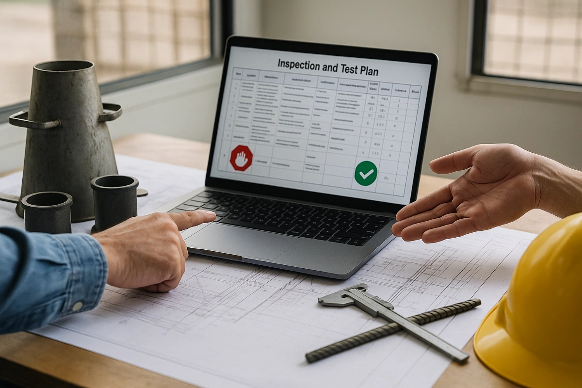
AI-assisted inspection and test plan connected to a method statement, with PDF and Excel export.
More than a static template
Unlike a downloadable Word or PDF template, this ITP is an AI-assisted editable starting point directly connected to its method statement. Every inspection activity, hold point, and acceptance criterion is structured and ready to adapt to your project.
- AI-assisted customization — Tailor inspection activities and acceptance criteria to your specific project scope.
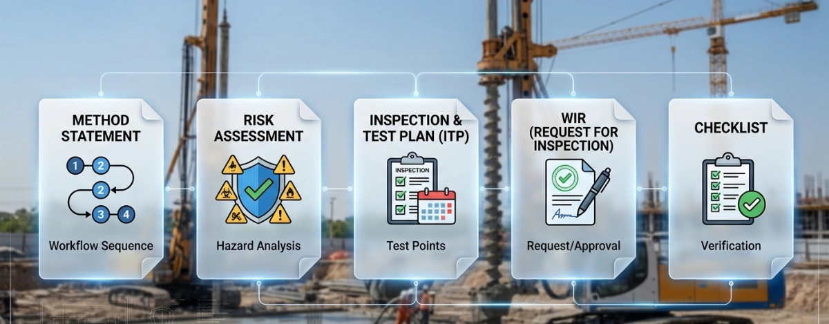
- Linked method statement — This ITP is connected to the corresponding method statement describing the work sequence.
- Multiple export formats — Download as a formatted PDF or editable Excel spreadsheet.
- Editable starting point, not a final document — Review and verify all content against your project specifications and standards before use.
What you can customize
When you save this ITP to your account, every inspection row becomes editable. You can add, remove, or modify:
- Inspection activity — Description of what is being inspected.
- Inspection type — Hold point (H), Witness point (W), Review (R), or Monitor (M).
- Responsibility — Contractor, subcontractor, engineer, or client.
- Frequency — How often the inspection occurs.
- Acceptance criteria — Referenced standard or specification requirement.
- Records — Forms, test reports, or checklists required as evidence.
Why this ITP is used
To ensure all valves are installed and tested to code, vendor, and project requirements with traceable records and controlled hold/witness points.
Who uses this inspection and test plan
QC inspectors, construction supervisors, commissioning engineers, client representatives, and vendor specialists.
When this ITP is prepared and submitted
From material receipt through final inspection and turnover, including line/system pressure testing.
Who receives or approves this ITP
Client/Engineer for review and approval before starting work.
Inspection scope
Covers receiving, preservation, fit-up, gasket/bolting verification, bolt-up execution, actuator interface, functional testing, and pressure testing.
Typical hold, witness, and review points
Hold: receiving of critical valves, controlled bolt-up for critical joints, ESD functional test, seat/shell tests, final acceptance. Witness: general bolt-up, supports, system pressure test.
Typical inspection records
MIR, IR, RFIs, bolt-up sheets, torque/tension calculations, calibration certs, stroke/loop tests, pressure test certificates, weld/NDE reports, DFT records, as-builts.
Important approval note
This ITP is an AI-assisted editable starting point, not a pre-approved document. Before use on any project, all inspection activities, hold points, and acceptance criteria must be reviewed and approved by the relevant parties (superintendent, principal contractor, or client representative) in accordance with your contract and project quality plan.
Always verify acceptance criteria against your applicable drawings, specifications, and regulatory requirements. Hold points must be confirmed with the relevant authority before work proceeds past that point.
Inspection and test plan
| Activity | Inspection / Test | Acceptance Criteria | Responsibility | Record |
|---|---|---|---|---|
| Receiving inspection | Visual/dimensional; cert review | Matches datasheet/P&ID; markings per MSS SP‑25; no injurious defects (MSS SP‑55). | QC / Client (W/H) | MIR; IR; photo log |
| Storage/preservation check | Visual/internal cleanliness | End caps fitted; no corrosion/ingress; preservation log current. | QC | Preservation log; IR |
| Pre-install verification | Document check; visual | Correct valve tag/line; orientation; F-F per ASME B16.10; supports identified. | QC / Supervisor | Checklist; RFI (if client W) |
| Support installation | Fit-up/WPS; NDE (as spec) | Per IFC; welds acceptable to code/spec; coatings restored. | QC / Welding Inspector | Weld/NDE reports; IR |
| Flange face condition | Visual/feeler gauge | Faces/grooves clean; defects within acceptance; alignment within project/PCC‑1 limits. | QC | IR; photos |
| Gasket/bolting verification | Material/grade/type check | Correct gasket type/class; bolts/nuts grade and length as per spec; no reuse. | QC | MIR; IR |
| Controlled bolt-up | Torque/tension verification | Target bolt load achieved within tolerance; uniform closure; 2–3 thread protrusion. | QC / Bolting Tech / Client (W/H for critical) | Bolt-up sheet; torque/tension calc; gauge certs |
| Actuator mounting & alignment | ISO 5211 interface check; run-out | Proper fit; run-out ≤ 0.5 mm TIR [Verify]; stops set; fasteners torqued. | QC / Instrument Tech / Vendor (W for ESD) | Fit-up/stroke sheet |
| Utilities hook-up | Leak check; pressure set | No leaks; pressure/quality per spec; correct terminations. | Instrumentation / QC | Loop check; IR |
| Functional stroking | Stroke timing; limit switches | Full travel; no binding; feedback within ±2% [Verify]; fail action correct. | Commissioning / QC / Client (W/H for ESD) | Stroke test record |
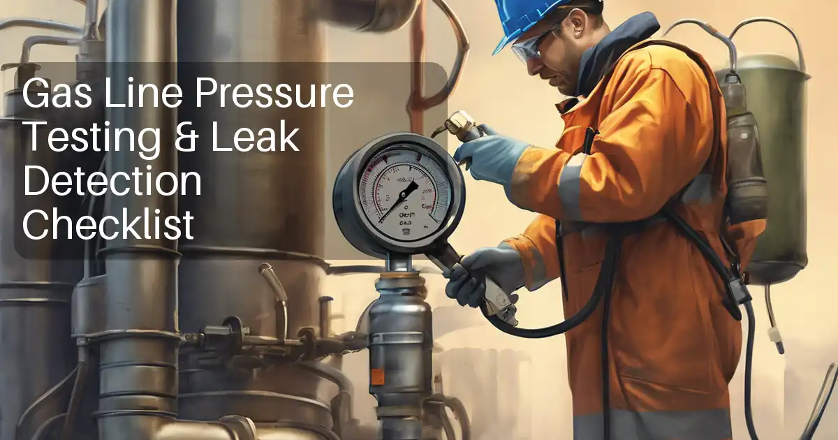
| Seat/shell test (if required) | API 598/ISO 5208 | Leakage rate/class as per spec; hold time per standard; no pressure decay beyond allowable. | QC / Client (H) | Pressure test certificate; gauge certs; log |
| System pressure test | Hydro/pneumatic per code | Test pressure/time per ASME B31.3/project; boundary integrity maintained; restoration verified. | QC / Commissioning / Client (W/H) | Test pack; IR; punchlist |
| Tagging/marking | Visual | Tag matches P&ID; permanent; flow arrow visible. | QC | Tag log; IR |
| Final inspection & documentation | Document completeness check | All records complete and signed; no open critical punches. | QA/QC / Client (H) | Dossier/Turnover pack |
This table is a read-only public reference. Download the PDF or Excel version, or customize this ITP to edit it for your project.
Frequently asked questions
Related method statement
This Inspection and Test Plan is associated with the Method Statement: Oil & Gas Valve Installation and Testing method statement, which describes the step-by-step construction sequence, resources, materials, equipment, safety controls, and environmental controls for this activity.
View the Method Statement: Oil & Gas Valve Installation and Testing method statement →Continue with related inspection, method statement, article, and checklist resources.