Electrical, Plumbing and HVAC in 3D Printed Houses: When to Install, Test and Close the Walls
Quick Answer: In a 3D printed house, MEP installation is planned before the print file is approved, installed in coordinated stages before, during or after printing, inspected and tested before concealment, then retested or commissioned after final connections. Electrical conduits, domestic water, drainage, heating loops, fuel-gas pipes, refrigerant copper, condensate and ventilation each need different routes, tests and release rules. Passing a pressure test alone does not always authorize closing the wall or releasing pressure.
Core rule: Treat every service penetration, concealed connection and pressure test as part of the approved printing sequence. A cavity intended for structural grout or insulation is not automatically available for a pipe. A successful pressure test, permission to conceal work, permission to release pressure and final commissioning are distinct decisions.
Why MEP coordination is different in 3D concrete printing
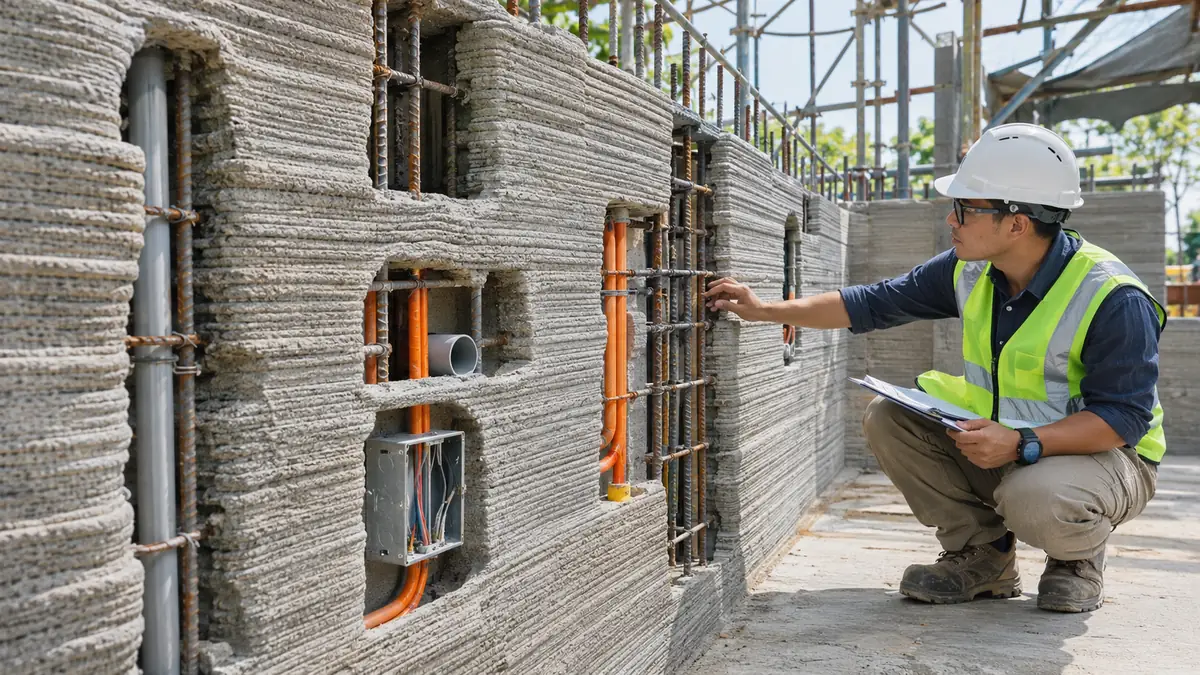
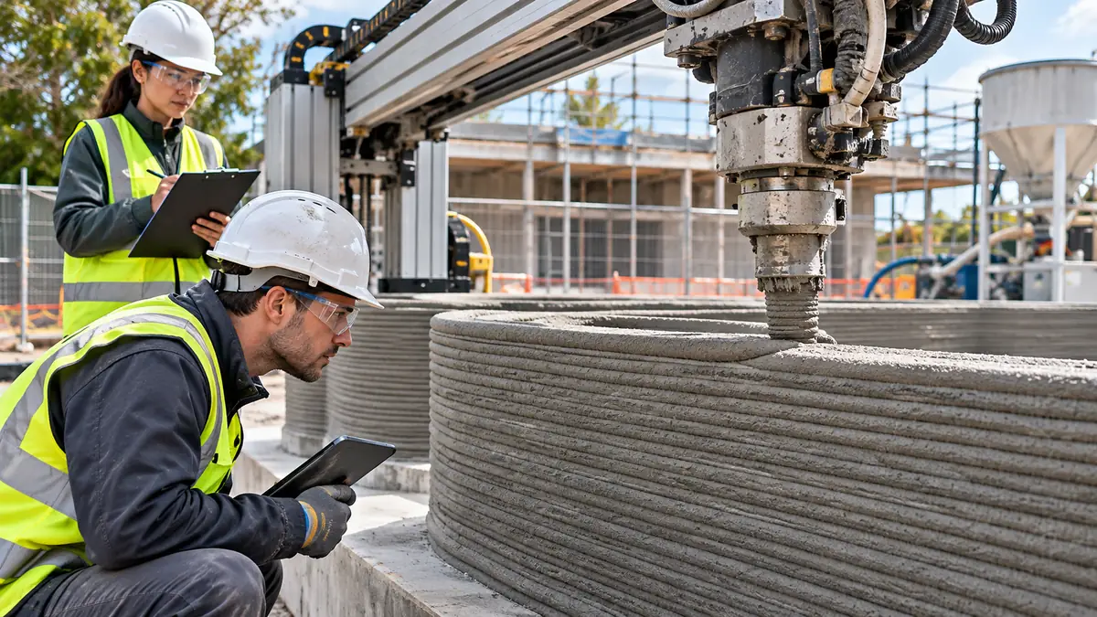
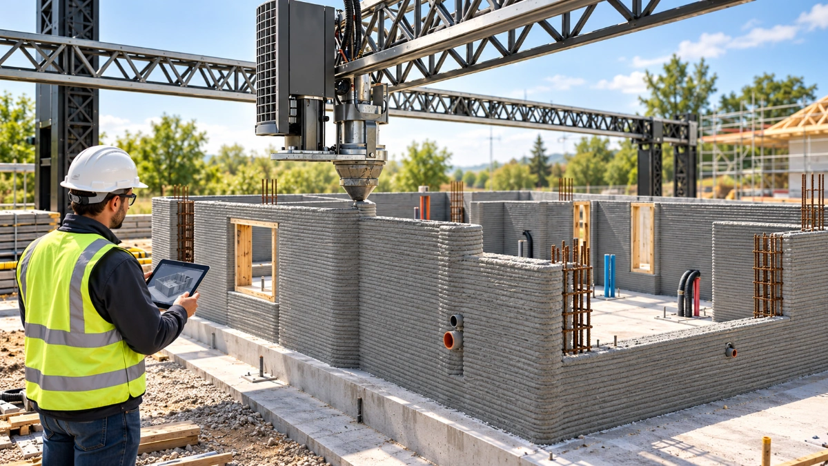
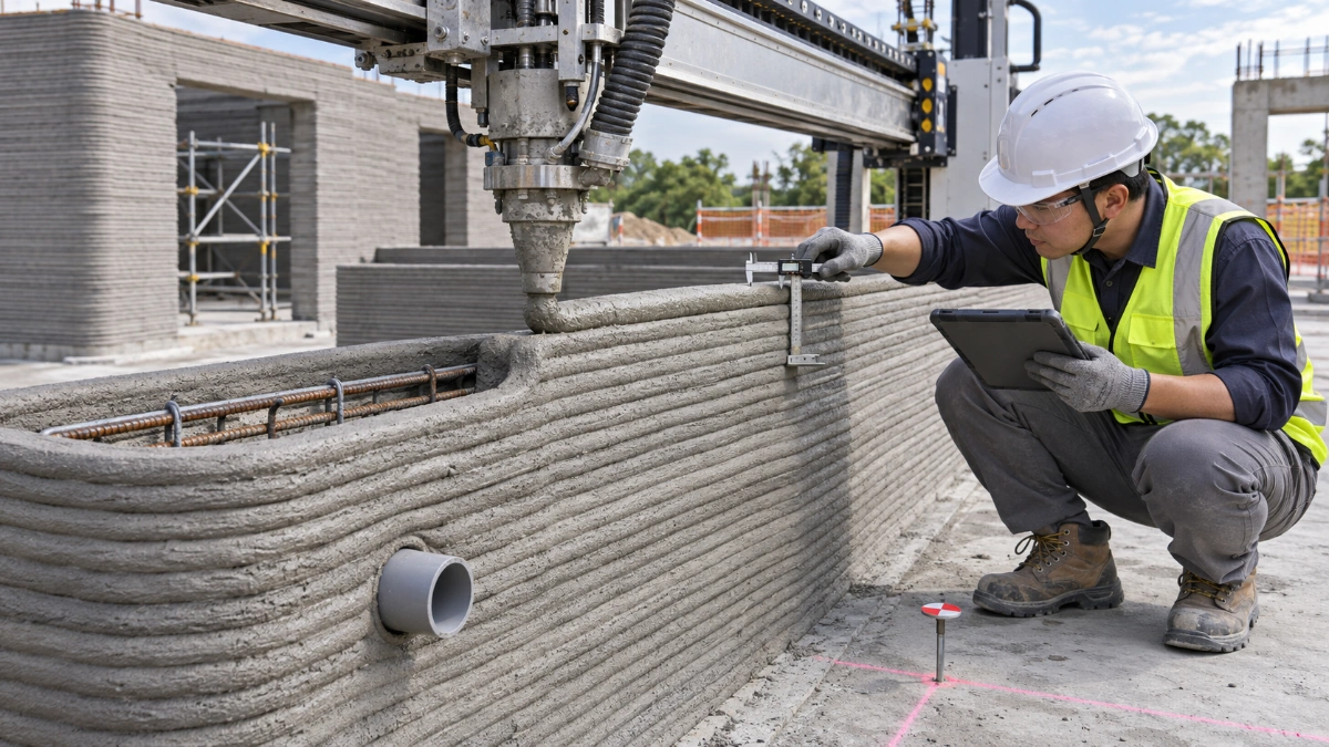
A conventional building can often be chased or framed for services after the main wall is built. With extrusion-printed concrete, the printer follows a predetermined toolpath, and successive layers may enclose internal voids, reinforcing cores and installed boxes. Chasing afterwards may affect structure, layer interfaces, thermal performance, weather protection or a qualified wall configuration. It may also be expensive or inaccessible.
A 2026 field study of German 3D-printed buildings documented deliberately planned electrical recesses, manual installation of boxes and conduits, and later processing for some service penetrations. The authors emphasize early coordination and an accessible service plane where feasible. This is a documented project approach—not a statement that every printer can automatically install MEP.
For the wider construction process see How 3D Printed Houses Are Built. This guide follows the complete electrical, mechanical and plumbing workflow on site, including testing and release.
The full MEP flow: before printing, during printing and after printing
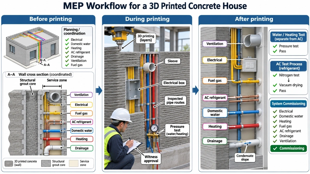
| Phase | Work that should be completed | Inspection / authorization |
|---|---|---|
| 1. Before printing | Freeze coordinated drawings and current model; confirm MEP interfaces, sleeves, boxes, reserved cavities, protected routes, structural/grout zones, access, insulation, material approvals, tests and installation sequence. | Issue coordinated print-path revision, clash record and approved MEP method/ITP with assigned hold and witness points. |
| 2. During printing | Install or protect designated embeds at permitted pauses; monitor position, supports, clearances, line identification, test status and ability to recover from print interruptions. | Check reinforcement/embeds before the next layers conceal them; stop affected work if a critical test or release is missing. |
| 3. After printing | Finish accessible services, pipe supports, insulation, connections, walls and penetrations; perform the required section and full-system tests, electrical/functional checks, sealing, flushing and commissioning. | Close nonconformances, retain pre-concealment evidence, record authorized pressure releases, sign off as-built service routes and handover. |
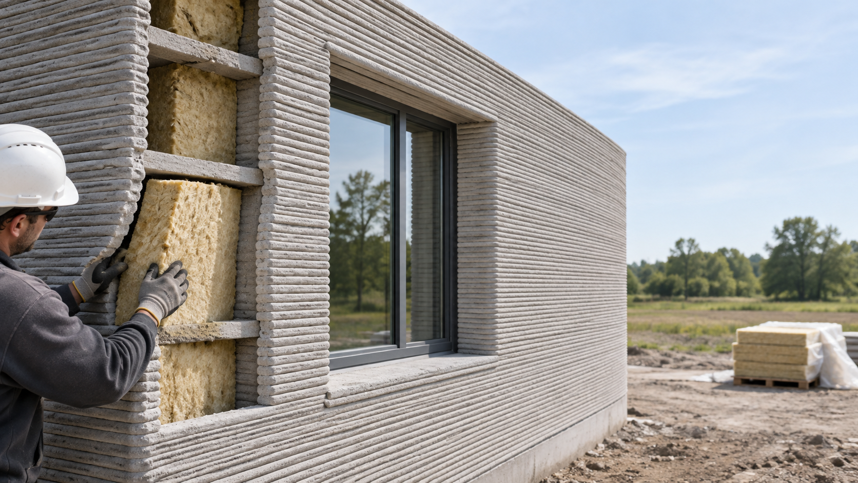
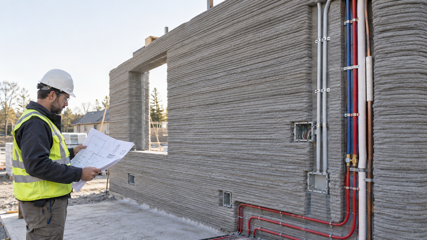
Some services are best installed in a separate accessible internal service zone rather than physically embedded in the printed concrete. A design may combine methods—for example electrical boxes at predetermined openings, domestic water in an internal lining, and a roof air-handling system whose ducts pass through engineered sleeves. Do not assume all services should be printed around.
Phase 1 — What must be finished before the printer starts?
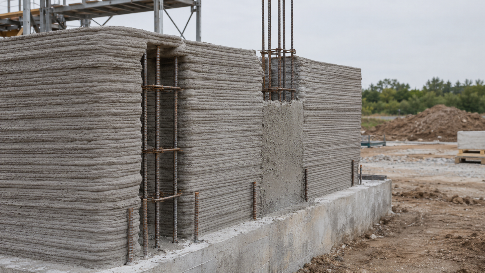
- Lock the coordinated design: align structural calculations, wall-core section, reinforcement drawings, architect's openings, MEP design and exact printer path/revision. Mark every permitted opening, box, embed and reserved service route.
- Classify every wall void: structural reinforced/grouted core, insulating cavity, ventilation/drainage void, deliberate service chase or inaccessible void. Do not reroute services into other categories without designer approval.
- Sequence trades: identify components positioned on the foundation, inserted at an intentional print pause, installed after the shell cures, or placed only in the interior service zone. Include tolerances and return-to-print authorization.
- Review electrical and ELV routes: locations of switches, sockets, data, alarm devices, lighting feeds, distribution boxes, earthing/bonding requirements, conduit bend radii and cable-pulling access. Protect boxes from cementitious material.
- Review water and drainage: accessible isolation valves, pipe insulation, hot-water expansion, supports, sanitary slope, vents, cleanouts, trap access and acceptable pipe joints in concealed locations.
- Review hydronic heating: floor or wall loops, manifolds, circuit identification, expansion joints, permissible crossing sleeves, no unauthorized joints in concealed loops and freeze protection during testing.
- Review gas and refrigerant systems separately: fuel-gas pipe materials, routes, joins, ventilation, permitted concealment and gas authority approvals; AC refrigerant-grade copper tubing, line-set insulation, brazing/connection requirements, service access and manufacturer system pressure limits.
- Review air and moisture control: ducts, ventilation openings, condensate drain fall, water-resistant penetrations, roof/window junctions, firestopping and airtightness around service boxes and sleeves.
- Plan the tests and release records: specify the accepted test medium, boundaries, test pressures, times, gauge and witness for each system, which elements must stay pressurized during covering and who may authorize release.
Design-freeze decision: If the piping design cannot be installed without cutting reinforcement, disturbing a load-bearing core or losing the approved drain gradient, stop before printing and revise the coordinated model. An RFI or design change now is usually safer than a hidden workaround later.
How should the print sequence accommodate MEP?
Provide a layer-by-layer or elevation-based interface schedule, even if the equipment is not capable of automatically placing services. The schedule should identify wall/segment, print elevation, required pause, installation task, permitted restart interval, inspector, photographs and release.
| Typical interface | When it happens | Before the printer resumes |
|---|---|---|
| Foundation sleeves and starter service routes | Before first layer or initial print release | Survey route and confirm no conflict with foundation starters or load-bearing cores. |
| Electrical recessed boxes and conduits | At planned recess/opening or after printing in an accessible service layer | Verify coordinates, attachment and no unwanted wall/air-barrier damage. |
| Water or heating pipe in approved cavity | At an approved installation pause or as a separate post-print fit-out | Check route, protection, support, appropriate preliminary testing and pre-concealment inspection. |
| Air ducts and ventilation sleeves | Before or at printing-defined penetration/lintel stage | Check opening size, supporting structural detail, fire/air sealing and access. |
| Refrigerant or fuel-gas line crossing wall | Prefer approved sleeved, serviceable route with correct separation and access | Verify pipe material, sleeve, joining/concealment permission, supports and required test stage. |
| Concrete core grouting / insulation fill | After printing at the separate approved hold point | Verify that no unapproved MEP occupies the core or drainage/insulation zone; relevant pipes released for encasement. |
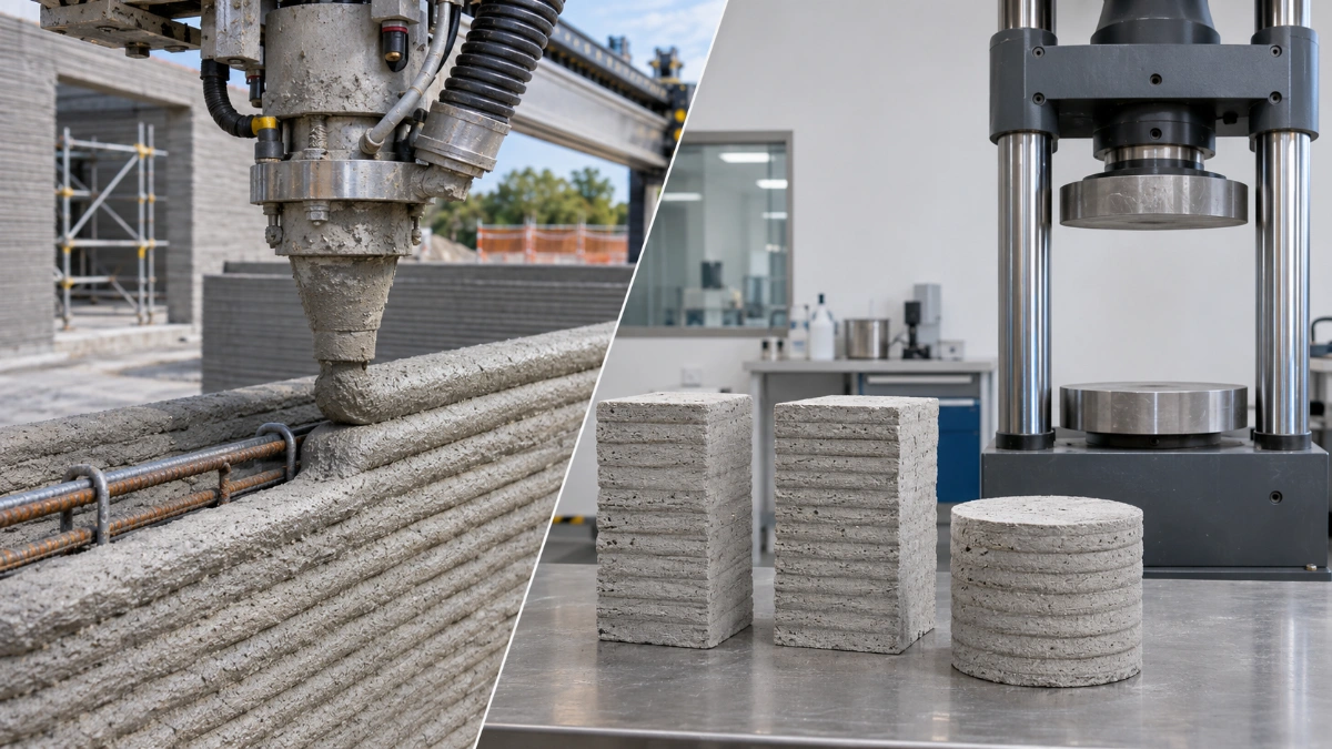
When installation needs a printing pause, record the start and duration, identify material setting and layer-interface restart controls, then resume only under the project-approved procedure. Refer to the 3D Printed Concrete QA/QC guide for the printed-material and process-related inspection requirements.
Phase 2 — Electrical and low-voltage services during printing
Electrical installation needs more than choosing an available empty slot in the wall. Consider the route, cable-pulling length, bends, box depth, conductor access, protection from wet printable material, accessibility of splices, separation from gas or water systems and required grounding/bonding. In some projects the most maintainable detail is a service cavity or surface-accessible route, not a permanently buried cable.
- Conduit pre-installation: position and restrain conduits so they do not deform under printing or infill pressure; cap open ends to exclude mortar; maintain approved pull routes and bend radius.
- Box and sleeve placement: use designed openings/recesses, avoid cutting a load-bearing printed web, and inspect airtightness and fire requirements where applicable.
- After printing: test conduit continuity and accessibility before pulling conductors; complete cable installation, connections, insulation/continuity/polarity and protective-device tests according to the applicable electrical code and approved procedure.
- Low-voltage systems: coordinate data, fire alarm, security and communications with power separation, equipment locations, testing and accessible terminations.
Pressure-testing requirements do not apply to electrical conduits as they do to pipes; the electrical inspections include appropriate circuit and functional tests.
Phase 2 — Plumbing: domestic water, hot water and sanitary drainage
Cold- and hot-water supply lines can be run through a purpose-designed accessible service plane, or through a specified cavity where the wall system, pipe material and installation rules permit it. Hot water needs expansion and insulation coordination, and all concealed joints need to comply with the chosen system's permitted installation method. A shutoff valve that cannot be reached after closure is not an acceptable maintenance solution.
Drainage and vent pipes differ from water supply: their function relies on gradients, trap seals and adequate flow paths. A vertical pipe inside an approved shaft may be straightforward; an unplanned horizontal run may require a slope that cannot be achieved inside a thin printed wall. Provide accessible cleanouts and avoid structural clashes.
When must domestic-water pipes be tested?
Normally the relevant section is tested once complete and before it is concealed; the finished system is checked again as required after final connections, repairs and commissioning. As a code example, the 2024 International Plumbing Code Section 312.6 specifies testing a completed section or entire water-supply system at not less than its working pressure for at least 15 minutes; its alternative air test applies only to pipe classes for which the code permits it. The adopted local edition, material manufacturer and project requirements govern, and may require different or more stringent procedures.
How do drainage and condensate tests differ?
For drainage/vent piping the adopted code may call for a water-head, air or other permitted test—not a water-supply pressure test. As one specific example, 2024 IPC Section 312.2 specifies a minimum 10 ft (3.048 m) head of water in specified sectional drainage/vent testing, held at least 15 minutes. Section 312.3 expressly prohibits testing plastic drainage piping with compressed air under that code provision. Confirm exactly which test the installed material, pipe system and local authority require.
Air-conditioning condensate lines need a separate installation check: correct gradient, accessible cleaning points, appropriate trap or pump as designed, water-flow test and observation for leakage/overflow. A pressure gauge on a water-supply line does not prove a condensate pipe drains properly.
Phase 2 — Hydronic heating pipes and underfloor heating loops
Hydronic heating may use PEX, multilayer polymer or another approved pipe system in floor screed or specially designed wall zones. Loops and manifold connections should be coordinated before concealment, with clear identifiers and accessible connection points. The designer should protect pipes from deformation, freezing, subsequent drilling, saw-cut control joints and hot-work activities.
When should heating pipes be pressure tested and kept under pressure?
Testing should take place after loop installation and before screed, covering or any printed closure that makes the route inaccessible. Some manufacturer procedures require the test to continue or the system to remain at specified monitored pressure during the covering operation as a damage indicator.
For example, the Uponor 2023 Residential Radiant and Hydronics Installation Handbook recommends 60 psi for at least 24 hours for the systems it covers and maintaining pressure during slab pours or finish-floor installation. A REHAU underfloor-heating installation guide describes a different 6 bar initial stable water-pressure test for 24 hours for its specified system, noting that pressure can change with the pipe's expansion and ambient temperature. These examples demonstrate why the test specification cannot be copied from one product to another. REHAU also advises against compressed-air pressure testing for its installation on safety grounds.
When can the heating-loop pressure be released?
Not automatically at the end of the 24-hour hold. Determine whether the approved procedure still requires monitoring while concrete, screed or subsequent covering is placed. Obtain and record the required witness/inspection release. Only then may the authorized installer transition the line to the specified commissioning, protective or operating condition. Protect water-filled circuits against freezing and retest if construction damage is suspected.
Phase 2 — AC refrigerant copper pipes and condensate
Refrigerant-grade copper tubing is a sealed refrigerant circuit with requirements that differ from domestic water or fuel-gas piping. Its selected size, allowable line length and elevation, connection method, oil return, supports, insulation, route and refrigerant compatibility are dictated by the equipment and mechanical design. Concealed or inaccessible joints may be restricted by the equipment manual and applicable code.
Where brazing is specified, qualified personnel should use the manufacturer's approved technique and contamination controls; nitrogen purging during brazing may be required to limit internal oxidation. Keep open pipe ends sealed until installation to prevent moisture and debris ingress.
What is the correct refrigerant test sequence?
- Complete the approved refrigerant piping and isolate equipment or components as the manual directs.
- Carry out the required strength and/or leakage test using the manufacturer- and code-approved inert test gas, generally dry oxygen-free nitrogen, with correct regulated equipment, pressure limitation and gauges. Never use oxygen or ordinary compressed air as a substitute for the approved refrigerant test medium.
- Maintain the specified pressure and time, adjusting interpretation for temperature effects as permitted; investigate any unexplained pressure change and repeat the appropriate test after a repair.
- Record satisfactory results, obtain any required witness approval, and have qualified personnel safely release test nitrogen when permitted by the specified procedure—not by an improvised release from an inaccessible pipe.
- Vacuum-dry/evacuate and verify the system as required before the prescribed refrigerant charge and commissioning. Do not confuse nitrogen tightness testing with vacuum moisture removal.
Manufacturer example, not a default: a published Daikin VRV-S R-32 installation manual for RXTA models specifies a 580 psi (4.0 MPa) nitrogen hold for 24 hours followed by vacuum drying and equipment-specific checks. Different units and refrigerants can have different test pressures. The relevant ASHRAE Standard 15 addenda specify safety requirements for approved inert test gases, test apparatus and field strength/leak testing; the installed equipment manual and adopted requirements must be checked before applying any value.
Refrigerant lines crossing printed walls require protective sleeves, coordinated fire/air sealing and continuous thermal insulation where applicable. AC condensate should be treated as a separate gravity/pumped drainage system with a fall/flow test and cleaning access; refrigerant tightness does not demonstrate condensate drainage performance.
Phase 2 — Fuel-gas pipes, approved copper and safe pressure testing
Fuel-gas piping is safety-critical and must never be treated as equivalent to an AC refrigerant line. Do not assume copper is allowed for fuel gas in every location. The gas type, local code, tubing/joint standards, permitted routing, corrosion protection, service access and authority approval determine whether copper or another pipe material is acceptable.
For new fuel-gas pipework, the approved pressure test is performed on a correctly isolated system using the test medium and procedures allowed by the adopted gas code, before the piping is concealed and before fuel gas is introduced. Appliances or other components not rated for the test must be protected or disconnected as required. Fuel gas itself and oxygen must not be used in place of the specified pressure-test medium.
As an example of a model-code procedure, the 2024 International Fuel Gas Code includes tests with specified pressure, instrument, isolation and duration requirements, including a minimum 10-minute duration in certain contexts. This does not mean ten minutes is enough for every gas-piping installation. Building type, volume, permit conditions and local amendments may impose different durations. A separate leakage check is required when gas service is safely brought into operation.
Suspected live fuel-gas leak: Stop work, protect and evacuate affected people, avoid creating ignition sources or operating electrical switches in the hazard area, and notify the gas provider and appropriate emergency/qualified personnel from a safe location. Do not treat it as an ordinary water-pipe repair or continue printing around the suspected leak.
Phase 2 — Ventilation ducts, fire protection and other building services
Mechanical ventilation requires early coordination of supply/extract duct positions, shafts, access panels, dampers, acoustic treatment, condensate and required fire/smoke separations. Duct penetrations and supporting lintels must be designed before printing, and duct airtightness, balancing and fire/smoke testing must follow the applicable mechanical/fire codes and specification. This is not the same as testing a liquid pipe.
Where a project includes sprinkler or fire-suppression piping, it requires separate licensed design, piping installation, pressure testing, flushing and acceptance in accordance with its governing fire standard. Do not adopt the domestic-water or radiant-heating numbers for fire-protection piping. Controls, sensors, earthing and data wiring also require their own continuity, functionality and commissioning checks.
Pressure-testing matrix: medium, hold period, concealment and release
Use the following table as a decision matrix, not a universal field test instruction. The numerical entries are examples from specific model-code provisions or manufacturer documents. Before use, check the actual jurisdiction, equipment, pipe material, approved test plan and qualified test procedure.
| MEP service | Test medium and example reference | When tested | When pressure can be released |
|---|---|---|---|
| Domestic hot/cold water | Typically water/hydrostatic test; 2024 IPC 312.6 example: at least working pressure for 15 minutes. Material limits and other adopted requirements may differ. | When a section is complete, before concealment; subsequent system verification as specified. | After passing and required witness/record sign-off, provided no pressure retention is specified for covering. Recheck after alterations. |
| Gravity drains and vents | 2024 IPC 312.2 example: water head for at least 15 minutes; 312.3 prohibits air tests of plastic piping under that section. | Before closure of pipe routes and again as code requires at final completion. | After appropriate leak/head test and acceptance; later verify slopes, traps, cleanouts and final function. |
| Hydronic radiant heating | Approved water/other permitted test; Uponor 2023 example 60 psi for at least 24 hours; REHAU example 6 bar initial stable water pressure/24h for a specific system. | After loop installation and before screed or enclosure, sometimes while covering proceeds. | Only after required test, witness and pressure-during-covering period are complete, and authorized safe next state is set. |
| AC refrigerant copper | Specified inert gas, commonly dry oxygen-free nitrogen; model-specific Daikin R-32 example 580 psi for 24h. Follow the equipment design and refrigeration safety requirements. | After piping/approved joints complete, before concealment as required, and before evacuation/charging. | Qualified controlled release of test nitrogen at the required transition to vacuum drying; later perform specified refrigerant commissioning/leak checks. |
| Fuel-gas piping, copper only where approved | Code-approved test medium; 2024 IFGC includes a 10-minute minimum in specified circumstances, not universal. | Before concealment and introduction of fuel gas, with appropriate system isolation/witness. | After documented test acceptance and safe authorized depressurization; separately leak-check when gas is introduced by qualified personnel. |
| AC condensate / drain pan | Water-flow/drainage test; verify fall, traps, pumps and joints rather than applying refrigeration test pressure. | Before concealment and during functional commissioning. | Not generally a sustained pipe pressure hold; confirm drainage flow, accessibility and no leakage. |
| Ventilation / ductwork | Approved duct leakage test, functional air-flow and balancing; fire/smoke system checks as applicable. | Before access is lost, then at air-system commissioning. | Release from any test condition as prescribed; signed results and functioning access/fire details required. |
| Electrical / low voltage | Conduit checks, continuity, insulation resistance, protective-device tests and functional commissioning; no pipe-style pressure test. | Before pulling/closing routes and after final installation. | Electrical clearance/energization only after approved safety tests; not a hydraulic release. |
Temperature and instrument effect: A pressure change can be caused by ambient temperature, elastic expansion of pipe materials, gas temperature stabilization or an actual leak. The test procedure must distinguish these causes using the specified method; an unexplained loss cannot simply be ignored. The test pressure must not exceed the lowest applicable safe rating in the test section.
When does a successful pressure test permit wall concealment?
There are four separate milestones that should be named in the ITP and release record:
- Test completed and accepted: an appropriate test medium, pressure, time and condition have been achieved, with traceable readings and approved acceptance criteria.
- Pre-concealment inspection released: the inspector has checked route, joints, supports, spacing, access, protection, photos and required structural/fire/envelope details.
- Covering/printing protection period completed: if the approved procedure requires retained pressure during screeding, printing, grouting or closing, it is monitored through that period.
- Authorized pressure release or transition: the competent person records when and how test pressure is removed, reduced or changed to a safe protective state, with retesting or commissioning planned as required.
Do not release solely because the holding clock expired. Heating loops may need to remain monitored during covering. Refrigerant nitrogen is released under the qualified procedure before vacuum drying and charging. Fuel-gas tests are safely ended before authorized gas-up checks. An electrical circuit has a different acceptance and energization process entirely.
MEP hold-point checklist: what must be signed off before closing a wall?
| Hold point | Required evidence | Reason for holding work |
|---|---|---|
| HP1 — Pre-print design release | Latest coordinated MEP/structural drawings, print-file ID, embed schedule, clashes and approved methods. | The printer must not close an unresolved structural/MEP conflict. |
| HP2 — Embed / sleeve placement | Correct position, fixing, opening/core status, pipe identification, insulation/fire/air-barrier details and photos. | A later print layer may make defects impossible to inspect or correct. |
| HP3 — Tests before concealment | Approved pressure/leak/electrical/duct/drain tests by relevant trade; signed reports and gauge IDs. | A passing visual inspection does not establish pipe or electrical performance. |
| HP4 — Restart or grout/insulation fill | Required pressure retention; monitoring plan; protected service route; print interface/stability checks. | Fresh printing or infill can displace a pipe, conceal a leak or damage a box. |
| HP5 — Completed system and handover | Final connections and retests, flushing/vacuum drying or commissioning, as-builts, owner access and O&M records. | Pre-concealment tests cannot replace post-installation functional verification. |
Use the existing 3D Printed Concrete Reinforcement and Embedded Services Inspection Checklist as a focused field record where applicable, together with the 3D Printed Concrete Inspection Guide and the project-specific 3D Concrete Printing Inspection and Test Plan. The ITP example must be adapted and reviewed against the actual construction contract.
What to do if a pipe leaks or fails its test
A failed test is a hold-and-investigate event, not permission to apply more sealant and continue burying the line.
- Protect people and stop the affected activity: stop printing, grouting, covering or commissioning in the affected area. For suspected live fuel gas or refrigerant release, follow emergency requirements and involve competent personnel.
- Isolate safely: identify the section and have the qualified trade depressurize or isolate it under the approved method; never loosen a fitting under unsafe stored pressure or damage the printed structural wall to locate a leak without authorization.
- Record evidence: location, wall/segment, line ID, pressure/temperature readings, test duration, recent printing operation, photos, suspected joint/pipe defect and relevant drawings.
- Find the cause: confirm whether pressure loss is leakage, thermal/elastic effect or an instrument issue; investigate accessible joints, damaged pipe, blocked line, poor sleeve, displaced bracket or construction interface.
- Approve the remedy: repair or replace under the system manufacturer's permitted procedure; seek structural and MEP design approval where chase/coring, reinforcement, fire separation or barrier continuity is affected.
- Retest and release: perform the applicable test on the repaired portion or whole system as specified, update the nonconformance and inspection records, and obtain clearance before concealment resumes.
Stop-work trigger: A suspected leak from a pipe that is about to disappear inside grout, screed or printed layers should be resolved at that time. Merely reducing the pressure, hiding the defect or moving the gauge is not a repair. Gas leakage or high-pressure refrigerant incidents demand specialist emergency procedures.
Common 3D printing MEP site problems and decisions
| Problem | Do not assume | Correct project response |
|---|---|---|
| Missed electrical box after printing | A new recess can be cut anywhere. | Check structural and envelope constraints; consider an accessible surface route or an approved engineered modification. |
| Water pipe crosses reinforced core | The cavity is free because it is hollow. | Preserve designed reinforcement and grout path; redesign route and reissue drawings. |
| Heating pipe pressure drops during grouting | It is only a temperature effect. | Hold affected work and investigate against the approved pressure-test criteria before closing. |
| Condensate cannot reach a drain by gravity | A small printed cavity can carry any slope. | Rework the route or use an approved condensate pump/access arrangement as designed. |
| Refrigerant line-set is exposed to rain before vacuum drying | The earlier nitrogen test was enough. | Inspect and dry/evacuate per manufacturer, retest where specified and document moisture-control measures. |
| AC copper conflicts with pipe insulation or firestop | Bare pipe can occupy the sleeve. | Coordinate required insulation, separation, sleeve sizing and approved fire/air seals. |
| Pipe coupling will be buried behind printed layers | Any connector is acceptable when concealed. | Check material-specific and code restrictions, move to accessible location or use an expressly approved concealed joint. |
| Printer resumes over uninspected embed | The print file alone establishes approval. | Stop and record the missed hold point; obtain the engineering/inspection disposition. |
| Damaged structural skin during chasing | A patch restores the original resistance. | Get structural design review and qualified repair before considering the work accepted. |
Case study A — A heating loop loses pressure during wall closure
In a hypothetical 3D-printed residential project, a hydronic floor loop was tested, photographed and approved before adjacent wall printing. During follow-on work, its monitored pressure falls unexpectedly. The foreman suspects a fitting has been damaged by a temporary support.
The team stops the local activity and protects the loop. The mechanical subcontractor checks the gauge, temperature and correct system section, investigates the route, then confirms a damaged connection. Instead of covering it, the contractor records the issue, arranges the approved replacement, repeats the relevant heating-system test and obtains an updated pre-concealment release. The test record identifies the period when pressure is still required during floor or wall covering and the separate permission for its later release.
Lesson: A pressure-test certificate issued yesterday does not automatically cover damage occurring today.
Case study B — A missing conduit after the wall is printed
An electrical outlet was omitted from the final printer file, and its intended location falls beside a load-bearing grouted core. The electrician proposes cutting a channel in the finished printed shell.
The site engineer checks the actual structural drawing, service plan and envelope detail. The affected work is held while the designer evaluates rerouting to an accessible internal service plane, surface mounting or a specific approved structural modification. The revised route and any air/fire/water seals are inspected before completion. The change is captured in the as-built drawings and the relevant RFI, inspection or nonconformance record where required.
Lesson: A missed electrical service is not automatically a minor finishing defect in a printed wall.
Suggested MEP Pressure Test and Release Record
For each distinct tested service or zone, an inspection record should include at minimum:
| Record field | Information to capture |
|---|---|
| Identification | Project, building, level, wall/segment, system (water/heating/gas/refrigerant), zone, pipe material and test boundary. |
| Authority and specification | Approved drawing/revision, governing code and manufacturer installation manual, method statement and ITP step. |
| Test setup | Medium, approved pressure, rated components, instrument/gauge ID and calibration, isolation boundaries and qualified operator. |
| Readings | Start/end time, time under stable test, recorded pressure and temperature, intermediate readings as required, observations and acceptance. |
| Witness and concealment | Installer, supervisor, inspector/witness, photographs of joints and routes, pre-concealment acceptance date. |
| Pressure protection/release | Whether pressure must remain during printing/covering, monitoring arrangement, authorized release time and responsible person. |
| Nonconformance and retest | Leak description, location, repair method/authorization, required test repeated and approval before closure. |
| Commissioning and handover | Final as-built coordinates, system service/fill/evacuation data, functional test, gas-up or refrigerant charge records as applicable. |
Do not issue a one-size-fits-all MEP pressure certificate. A useful shared record layout can be standardized, but testing instructions and acceptance fields must be system specific.
Key questions before handing over a 3D printed home
- Are all MEP routes shown on the as-built model and can critical valves, junctions, manifolds, cleanouts and connections be maintained?
- Were every applicable concealed-service and interface inspection and test completed before closing the related section?
- Was each test performed using the approved medium, pressure, duration, instrument and qualified operator?
- Was pressure retained and finally released at the specified stage, with the responsible person's sign-off?
- Were any leaks, missed sleeves, added openings or other changes repaired and retested with structural/envelope approvals where needed?
- Have electrical, domestic water, heating, refrigerant, gas, drain/condensate, ventilation and fire-protection commissioning records been collected as applicable?
Related Quollnet construction guides
3D Printed Concrete Reinforcement — reinforced cores, openings, foundation/roof connections and critical no-drill areas.
3D Printed House Insulation and Thermal Performance — thermal bridging, cavity insulation and continuous air/water barriers around penetrations.
3D Printed Concrete Inspection Checklist — pre-print, during-print and reinforcement/embedded-services inspections.
3D Printed Concrete QA/QC — inspection hold points, test evidence, deviations and acceptance.
Bottom line: The MEP work programme for a 3D printed house must be designed alongside the print programme. Plan service routes, install at the right stage, test before concealment, keep systems under monitored pressure only when the approved procedure calls for it, and finish with documented release, retesting and commissioning. What matters is a safe, inspectable and maintainable completed building—not simply a successfully printed shell.
References
Construction detailing in 3D concrete printing from real-world building projects (Bartels, Lange and Kesting, 2026) — Discover Civil Engineering / Springer Nature.
2024 International Plumbing Code — General Regulations and Section 312 Testing — International Code Council.
2024 International Plumbing Code — Section 312.2 Drainage and Vent Water Test — International Code Council.
Residential Radiant and Hydronics Installation Handbook (7th ed., 2023) — Uponor.
Underfloor Heating Floor Systems Installation Guide — REHAU.
2024 International Fuel Gas Code — Chapter 4 Gas Piping Installations — International Code Council.
ANSI/ASHRAE Addendum q to ASHRAE Standard 15-2022 — ASHRAE.
Daikin VRV-S R-32 Installation Manual — RXTA Series — Daikin.
ICC 1150-2026 — Standard for 3D Automated Construction Technology for 3D Concrete Walls — International Code Council.
ISO/ASTM 52939:2023 — Additive Manufacturing for Construction — Qualification Principles — ISO/ASTM.