3D Printed Concrete Walls: Inspection & QA/QC Guide
Quick Answer: 3D printed concrete quality control should verify more than compressive strength or the finished appearance of the wall. A practical QA/QC system controls the qualified wall system, approved digital model, printer setup, material batch, reinforcement and embeds, layer geometry, extrusion continuity, time between layers, interruptions, environmental conditions, curing, testing and the final as-built record. Acceptance criteria should be defined before printing starts and tied to the approved project specification, qualified process and applicable code or standard.
The central QA/QC difference: conventional concrete quality control often focuses heavily on the delivered material, placement and hardened test results. With 3D concrete printing, the manufacturing process itself can affect geometry, layer bonding and structural behavior.
The QA/QC record therefore needs to preserve what was printed, how it was printed and what changed while it was being printed.
Why is QA/QC different for 3D printed concrete?
In extrusion-based 3D concrete printing, cementitious material is deposited in successive beads and layers according to a digital toolpath. The final wall is influenced not only by the material formulation but also by the printer, nozzle, deposition rate, print speed, layer timing, geometry, reinforcement strategy and interruptions.
This matters because two walls made from nominally similar material can have different performance if their process histories differ. Layer interfaces may become preferential planes of weakness, the wall may deform while it is being built, and deviations in bead width or layer position can accumulate into dimensional errors.
The National Institute of Standards and Technology (NIST) has highlighted the relationship between material properties, machine settings, process parameters and structural performance as a central issue in additive construction. That is why a 3D printed wall should not be treated simply as conventional concrete that happened to be placed by a robot.
For a broader explanation of the complete construction process, see Quollnet’s guide to how 3D printed houses are actually built.
QA and QC are related, but they are not the same
Quality assurance (QA) establishes the planned system: approved materials, qualified printing process, responsibilities, inspection stages, acceptance criteria, records and escalation rules.
Quality control (QC) is the execution of that system: checking calibration, reviewing batches, measuring printed geometry, recording interruptions, inspecting reinforcement, taking samples, reviewing test results and documenting defects.
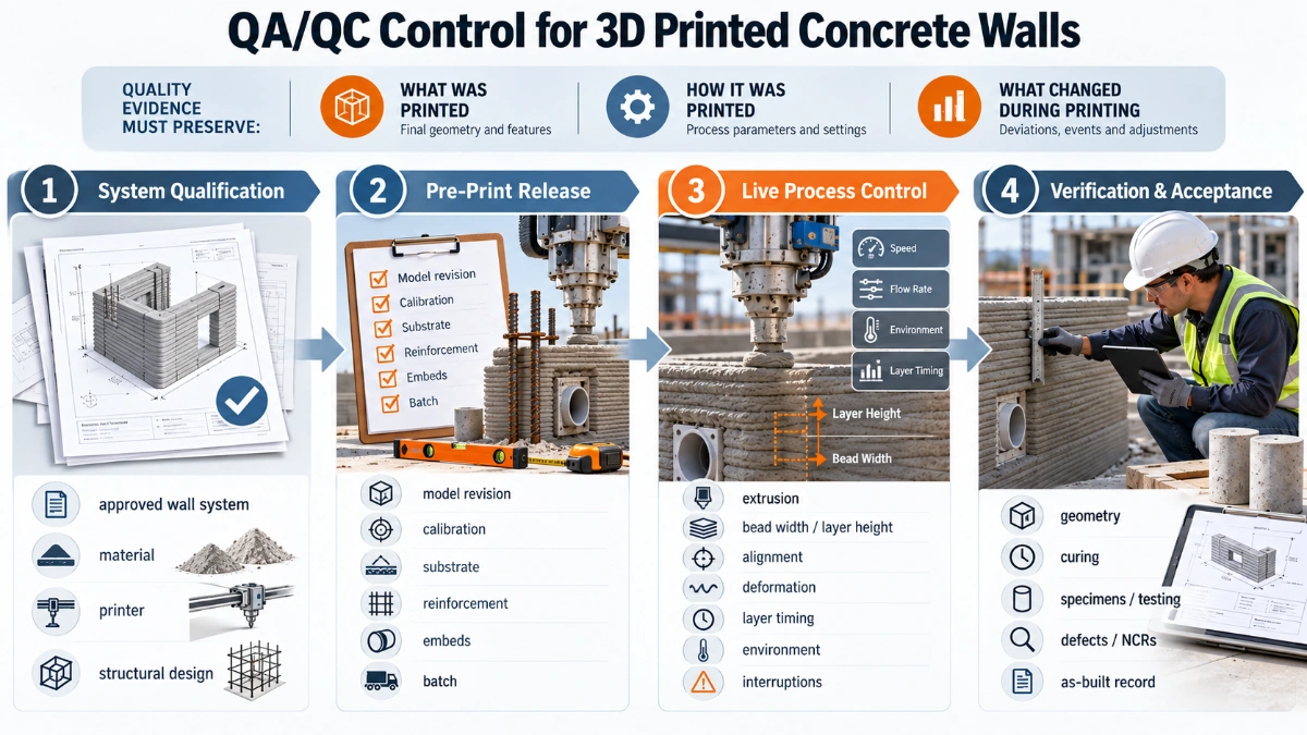
A useful project structure is to control the work in four stages:
| Stage | Main QA/QC question | Typical evidence |
|---|---|---|
| 1. System qualification | Has this wall system, material and printing process been qualified for the intended use? | Approved system data, qualification tests, structural design, material requirements, approved procedures. |
| 2. Pre-print release | Is the site ready to print the correct wall using the correct revision and setup? | Approved model, print file, calibration, substrate checks, material batch, reinforcement and embed inspections. |
| 3. Live process control | Is the wall being produced within the qualified process window? | Layer dimensions, timestamps, environmental readings, machine/process logs, photos, interruption records. |
| 4. Verification and acceptance | Does the completed work meet the approved geometry, material and structural requirements? | As-built inspection, samples/tests, curing records, defect dispositions, repair approvals and final acceptance record. |
1. Qualify the wall system before site production
The most important QA decision happens before the first production wall is printed. The project should define what constitutes the approved wall system and how compliance will be demonstrated.
ICC 1150-2026 establishes minimum requirements for materials, qualification, inspection and structural design of 3D printed wall systems and their connections. It addresses multiple wall configurations, including single-shell, multi-shell and reinforced-core systems, with or without conventional reinforcement or infill.
ISO/ASTM 52939:2023 takes a broader process-oriented approach to quality assurance for additive construction. It addresses quality-relevant characteristics, additive-construction operations and project activities, while explicitly not replacing project-specific design approval or material-property testing.
Define the approved system
The QA plan should identify, as applicable:
- the approved cementitious material or material family;
- the printer, pump, mixing system, hose and nozzle configuration;
- the wall geometry and layer configuration;
- the reinforcement, grout, concrete infill or fiber strategy;
- connections to foundations, floors, roofs and adjacent walls;
- the approved printing procedure and operating limits;
- required mock-ups or qualification prints;
- required specimens, companion walls or test panels;
- dimensional tolerances and surface requirements;
- the inspection, witness and hold points; and
- who has authority to stop, restart, accept or reject the work.
Do not create acceptance criteria after a problem occurs. If maximum interruption time, permitted geometric deviation, bead dimensions or required testing matter to performance, the project should define the relevant criteria before production printing begins.
2. Build the inspection and test plan around the printing sequence
A 3D-printing Inspection and Test Plan (ITP) should follow the actual sequence of work rather than reuse a generic concrete ITP unchanged. The ITP should identify what is checked, the acceptance source, the responsible party, the record produced and whether the point is a hold, witness, surveillance or review point.
Quollnet’s Inspection & Test Plan guide explains how hold points, witness points and acceptance criteria are normally structured on construction projects.
A 3D-printed wall does not normally require a different Work Inspection Request (WIR) form merely because the work is printed. The project can use its normal WIR workflow, while the inspection description and attachments identify the relevant wall or print segment, approved model/print-file revision, ITP point, reinforcement or embeds, process records and any required test evidence. ICC 1150-2026 establishes inspection and construction-quality requirements, but it does not create a universal project WIR form. For the general workflow, see Quollnet’s Work Inspection Request (WIR) guide.
Useful hold points for printed-wall work
Project requirements vary, but candidate hold or witness points may include:
- release of the approved digital model and print file;
- foundation/substrate and setting-out approval before the first layer;
- printer setup and calibration verification;
- approval of the production material batch or batch sequence;
- reinforcement, starter bars, embeds and service sleeves before they become inaccessible;
- restart approval after an interruption exceeding a defined threshold;
- completion of a wall before concealment, infill, lining or finishing; and
- review of required test results before structural loading or subsequent work.
3. Pre-print inspection: what should be checked before extrusion starts?
Approved model and print-file revision
The site team should confirm that the printer is using the current approved geometry. This includes wall locations, thicknesses, openings, internal cavities, reinforcement zones, embed positions and interfaces with conventional construction.
A revision mismatch in digital construction can repeat the same error automatically. The print file therefore deserves the same document-control discipline as an approved construction drawing.
Foundation, substrate and setting out
The first layer establishes the physical reference for everything above it. Check foundation level, wall setting-out, starter reinforcement, anchors, penetrations and local surface condition against the approved design.
The printer coordinate system should correspond to the project survey control. Any offset between the digital model and physical setting-out can propagate through the entire wall.
Printer setup and calibration
Record the printer identification and the calibration or verification required by the approved procedure. Relevant checks may include machine position, level, nozzle reference, working envelope, coordinate alignment, motion accuracy and any sensors relied on for process control.
Calibration is not merely a maintenance issue. If machine position is wrong, otherwise correct material can still produce nonconforming geometry.
Material identity and batch traceability
The inspector should be able to trace the printed work to the material actually used. Depending on the system, records may include material delivery or lot number, constituent batches, mix ID, admixture or accelerator dosage, mixing time, water addition, production timestamp and the wall or print segment that consumed the batch.
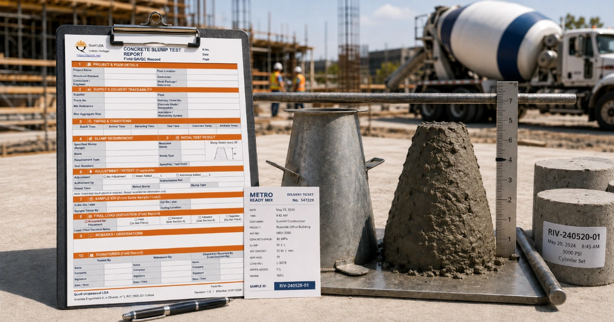
Printable cementitious materials must achieve a difficult balance: they must move through the delivery system and nozzle but stiffen sufficiently after deposition to retain geometry and support subsequent layers. This balance is why conventional fresh-concrete checks alone should not automatically be assumed to prove printability.
Reinforcement, embeds and openings
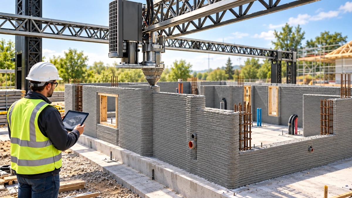
Confirm reinforcement, anchors, sleeves, electrical boxes, service openings, inserts and other embedded items at the stage required by the approved sequence. Some items are placed before printing, some between layers and some within cavities that will later be grouted or filled.
The inspection timing matters because a missed item may become difficult or structurally undesirable to add after the printer has passed its location.
Environmental conditions
Temperature, wind, sun, humidity and rain can affect material evolution, exposed layer surfaces and the timing between layers. Record environmental conditions at the frequency required by the project procedure, particularly when conditions can change the qualified printing window.
4. During printing: control the process while defects are still recoverable
Live inspection is where 3D concrete printing differs most visibly from conventional placement. The objective is not to watch the machine continuously without purpose; it is to monitor the characteristics that indicate whether the process is remaining stable and within the approved operating window.
Extrusion continuity
The deposited bead should remain continuous unless a planned stop is part of the print strategy. Look for under-extrusion, over-extrusion, gaps, tearing, irregular flow or abrupt changes in bead shape.
When a change occurs, record the time, location, affected layers and any machine or material adjustment. A photograph without location and process context is often not enough to investigate the issue later.
Bead width, layer height and alignment
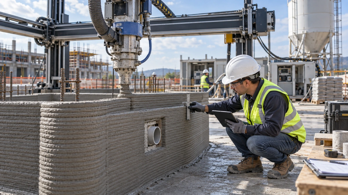
Printed geometry should be compared with the approved dimensions and tolerances. The project may monitor bead width, layer height, wall thickness, layer offset, wall position, plumbness or other geometry appropriate to the system.
NIST research on print fidelity emphasizes that process conditions and material rheology can produce shape deformation during construction. Dimensional checking is therefore both a final inspection issue and a live process-control issue.
Buildability and deformation
Each deposited layer has to support the next without excessive spreading, slumping or cumulative distortion. A wall that starts within tolerance can progressively deform as additional layers are placed.
Inspectors should distinguish an intentional geometric feature from a progressive process deviation. If deformation is increasing, the correct action may be to hold the print and investigate rather than wait for the wall to reach full height.
Nozzle clearance and contact
Unexpected nozzle contact can disturb previously printed material, reinforcement or embeds. Nozzle clearance, path and local collisions should therefore be treated as quality-relevant events when they affect the deposited wall.
Time between layers
The interval between successive layers can influence the quality of the interface. Long delays, rapid material evolution, drying of the exposed surface or contamination can change the condition onto which the next layer is deposited.
The project should define how layer timing is monitored and what happens when the qualified or approved interval is exceeded. The answer may be inspection, surface preparation, testing, engineering review or another approved disposition; it should not be improvised by the operator alone.
Reinforcement and embedded items during the print
If reinforcement or embeds are installed during printing, record their placement before they are concealed. Verify location, continuity, required cover or cavity geometry and any required connection to conventional reinforcement.
5. Print interruptions and restart interfaces need their own control
A printer stop is not automatically a defect. Planned pauses may be part of the construction method. The QA/QC concern is whether the interruption changes the condition of the layer interface or pushes the process outside the qualified sequence.
The interruption record should normally identify:
- wall or print segment;
- layer or elevation at the stop;
- start and restart time;
- reason for the interruption;
- material condition and environmental conditions;
- any cleaning or surface preparation;
- any material discarded or remixed;
- inspection performed before restart; and
- required approval or engineering disposition.
This information becomes particularly important if cracking, delamination or poor bond is later suspected at the restart elevation.
6. After printing: verify the wall before subsequent work hides it
Dimensional and geometric inspection
Check the completed wall against the approved geometry and project tolerances. Depending on the design, this may include wall position, overall thickness, height, plumbness, openings, connection zones, cavities, bearing locations and interfaces with conventional construction.
Modern projects may use manual measurements, survey instruments, laser scanning or other digital measurement methods. The technology used is less important than having defined acceptance criteria and a traceable record.
Visible condition
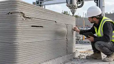
Inspect for cracking, layer separation, voids, local collapse, tearing, inconsistent beads, damage, unplanned gaps and suspicious restart interfaces. Not every visual irregularity has the same structural importance.
A separate Quollnet visual field guide is planned for identifying common 3D printed concrete defects. This QA/QC article focuses on the control system rather than trying to classify every defect.
Curing and protection
Printed walls still contain cementitious material that requires appropriate curing and protection. The approved method should address exposure, moisture loss, temperature and protection from damage in a way suitable for the material and wall system.
Curing records should be tied to the actual printed element, not kept as an unrelated general site note.
7. Testing: compressive strength is important, but it is not the whole acceptance system
Conventional concrete quality control often gives compressive strength a dominant role. Printed cementitious systems can require a broader view because layer-by-layer deposition may introduce directional behavior, interlayer interfaces and geometry that are not represented by a standard monolithic specimen.
NIST notes that some conventional material and structural test methods may not be directly applicable to 3D concrete printing, and current practice may use companion walls or printed elements from which representative specimens are taken.
The project’s qualified test plan may address, as applicable:
- compressive strength;
- flexural or tensile behavior;
- interlayer bond or shear behavior;
- density or material consistency;
- reinforcement-to-printed-material behavior;
- dimensional or geometric conformity;
- durability or exposure-related properties; and
- full-scale or system-level structural verification.
Do not assume that one familiar concrete test can certify the entire printed system. The required tests should follow the approved design, material qualification, project specification and applicable standard.
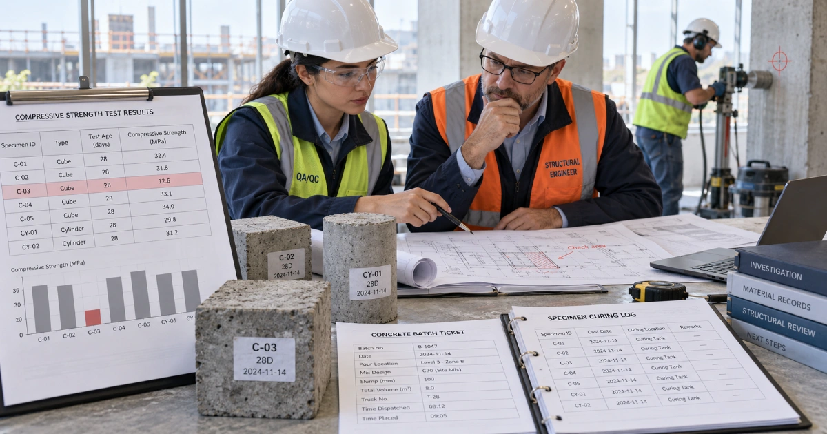
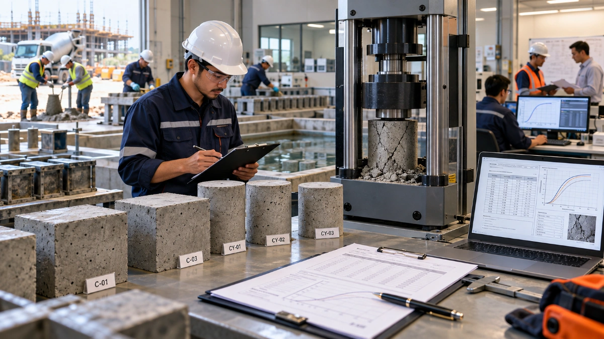
For conventional cube/cylinder fundamentals, specimen handling and result interpretation, see Quollnet’s concrete compressive strength testing guide. Those principles can remain relevant, but printed-wall acceptance may require additional system-specific evidence.
8. How should defects and deviations be handled?
A process deviation does not always mean the wall must be demolished, and a visually imperfect bead does not automatically mean the wall is structurally unacceptable. The correct response depends on what requirement was breached and whether the deviation affects structural performance, durability, geometry, interfaces or later construction.
A practical sequence is:
- Identify and preserve the condition. Record location, layer, time, photographs and relevant process data before repair.
- Compare with the approved requirement. Determine whether the issue is actually outside the specified tolerance or process limit.
- Control the work. Hold or stop affected work when continuing could conceal the issue or make recovery harder.
- Escalate when required. Obtain the appropriate technical or engineering disposition.
- Repair only to an approved method. Do not erase the evidence before the repair decision is documented.
- Verify and close. Confirm the repair or disposition and retain the closure record with the print history.
Quollnet’s Observation vs NCR vs Snag vs Defect guide helps distinguish records that are often confused on construction projects. When the work or material fails to meet a defined requirement, the NCR guide explains the normal non-conformance workflow.
9. What records should be retained for a 3D printed wall?
The most valuable 3D-printing QA/QC record is one that lets a later reviewer reconstruct what happened without relying on memory.
A project record may include:
- approved drawing/model revision and print-file identifier;
- wall or print-segment identifier;
- printer and nozzle identification;
- setup and calibration record;
- operator and inspection personnel;
- material/mix ID and constituent or batch traceability;
- print start and finish timestamps;
- environmental conditions;
- layer or geometry measurements;
- machine/process data required by the procedure;
- reinforcement, embed and opening inspection records;
- planned and unplanned interruption records;
- photos tied to location and time;
- specimen and companion-wall IDs;
- test results;
- as-built dimensional inspection;
- defects, NCRs, technical dispositions and repair records; and
- final acceptance or release record.
10. Common QA/QC mistakes to avoid
| Mistake | Why it matters |
|---|---|
| Treating the printer as a black box | Process changes may alter geometry or interfaces even when the material batch is unchanged. |
| Using compressive strength as the only acceptance measure | Printed systems can introduce directional and interlayer behavior not captured by one strength result. |
| Relying only on final visual inspection | The event that caused a defect may no longer be visible or reconstructable after printing. |
| Failing to control digital revisions | The machine can reproduce an incorrect geometry consistently and quickly. |
| Ignoring interruptions | Restart interfaces may have different conditions from continuously deposited layers. |
| Making undocumented site adjustments | Later test results cannot be meaningfully linked back to the process that produced the wall. |
| Repairing before documenting | The original condition and cause may be lost, weakening both engineering review and traceability. |
11. A practical acceptance logic for site teams
The site inspector does not need to become the printer designer or material scientist. The field role is to confirm that production matches the approved system and to recognize when the work has moved outside it.
Approved system + correct revision + verified setup + controlled material + monitored printing + documented interruptions + required tests + accepted as-built geometry = defensible QA/QC evidence.
Where the project does not yet have defined acceptance criteria for a print-related characteristic, that gap should be resolved through the designer, specialist supplier, qualified procedure or applicable authority rather than replaced with an arbitrary field rule.
What comes next in the 3D-printing QA/QC cluster?
This guide establishes the overall control framework. Three separate Quollnet articles can then go deeper without repeating the same material:
- 3D Printed Concrete Defects: A Visual Field Guide — what common defects look like, probable causes and when they require engineering review.
- 3D Printed Concrete Inspection Checklist: Before, During & After Printing — a field-ready sequence inspectors can use during an actual print.
- How Is 3D Printed Concrete Tested? — specimens, companion walls, directional behavior, interlayer testing and interpretation.
References
ICC 1150-2026 — Standard for Automated Construction Technology for 3D Printing Walls
NIST — Additive Manufacturing with Cement-based Materials
NIST — Additive Construction in Practice: Realities of Acceptance Criteria
NIST — Print Fidelity Metrics for Additive Manufacturing of Cement-based Materials
ACI Committee 564 — 3-D Printing with Cementitious Materials