Testing 3D Printed Concrete: What Engineers Must Verify Before Acceptance
Quick Answer: 3D printed concrete is tested by qualifying the printable mix and printing process, then verifying the hardened material and wall system with representative specimens and project-defined acceptance criteria. Compressive-strength tests remain important, but conventional cast cubes or cylinders alone cannot establish the strength of layer interfaces, direction-dependent behavior, print interruptions, or structural adequacy of a completed printed wall.
The field decision: A satisfactory concrete strength result is evidence about the specimen tested—not automatic approval of the 3D printed wall. The engineer needs to know what was sampled, how it was printed, which direction it was tested, and which requirement the result is being compared with.
Why is testing 3D printed concrete different?
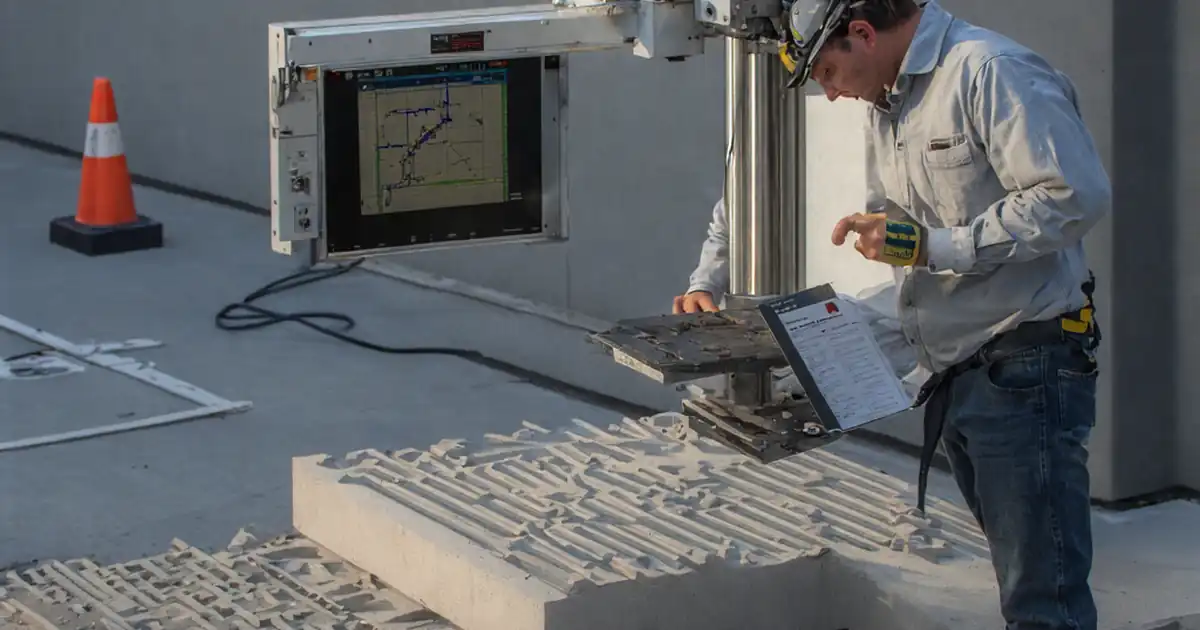
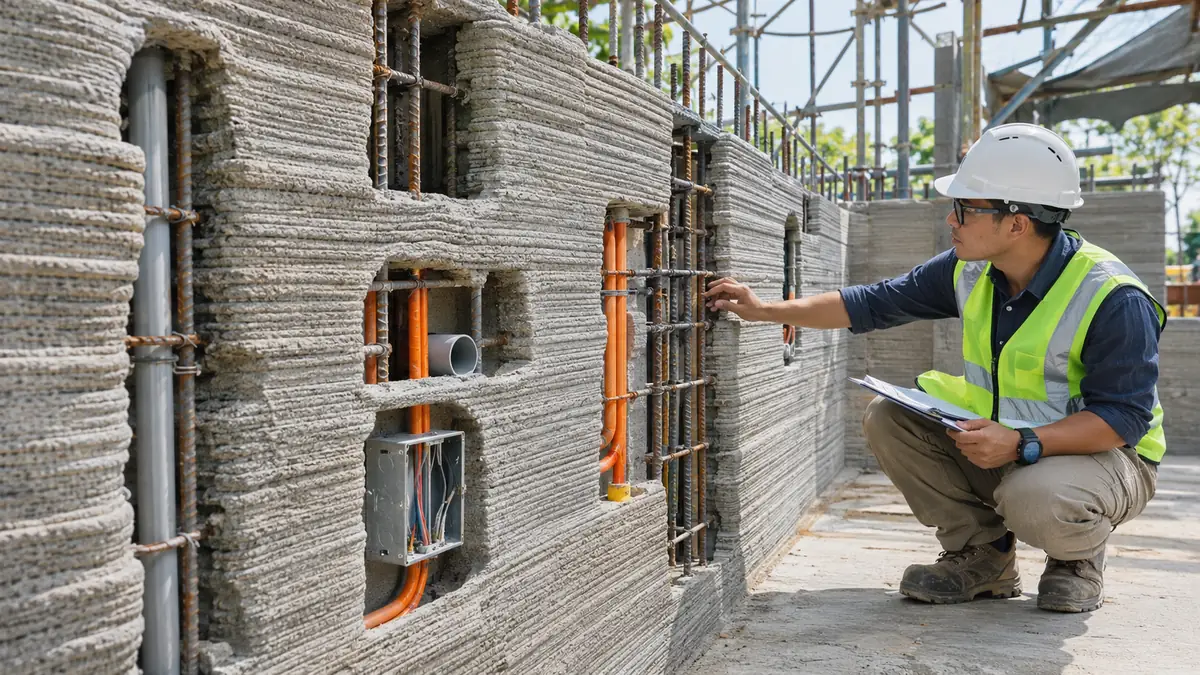
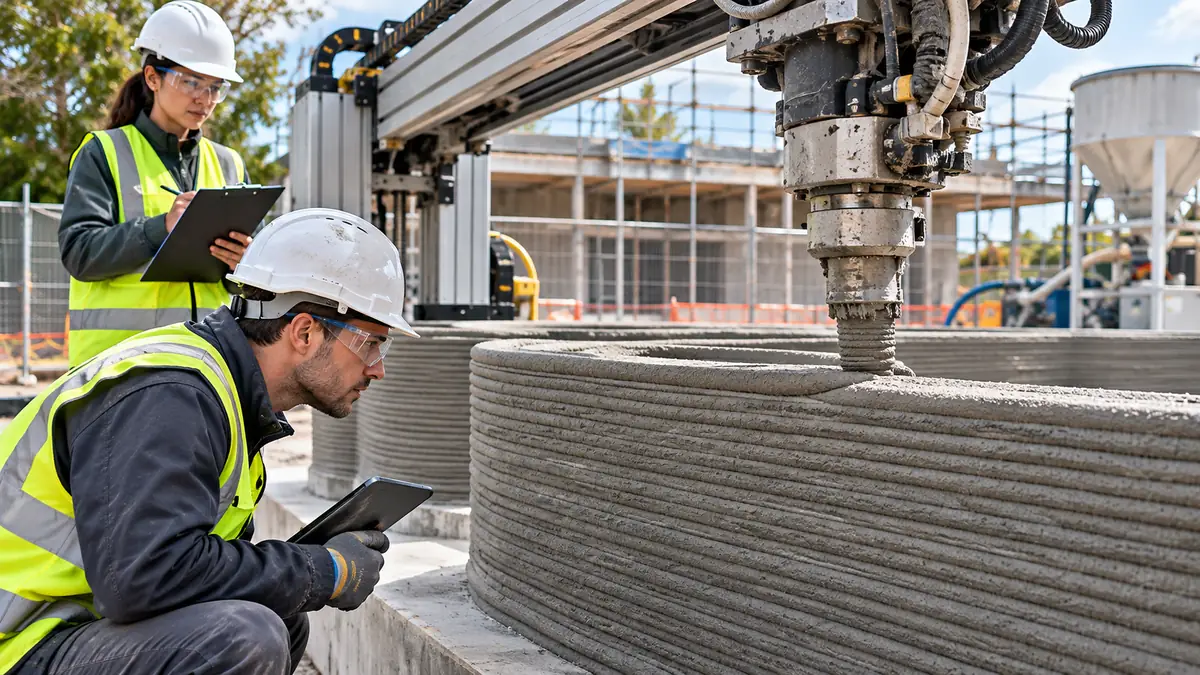
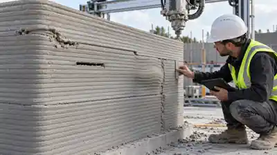
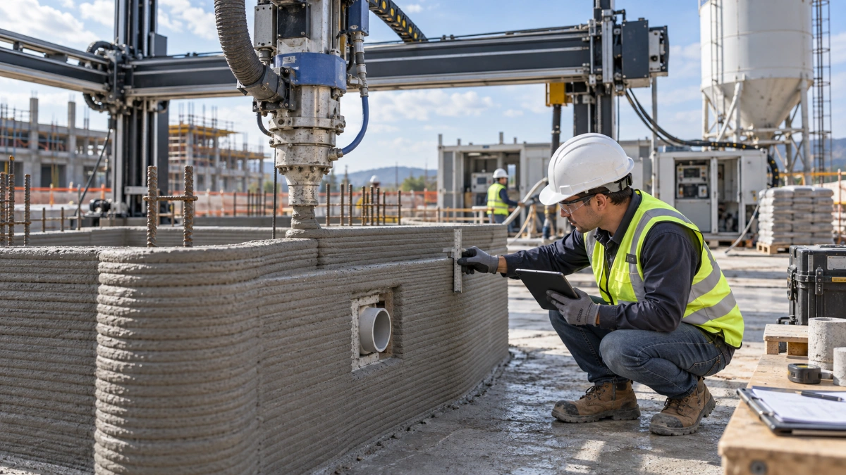
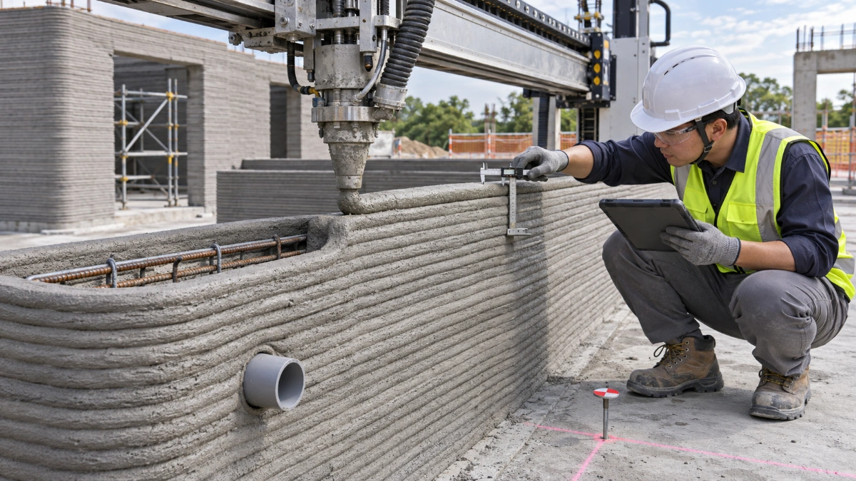
Extrusion-based 3D concrete printing (3DCP) places cementitious material in successive beads or layers rather than casting it into conventional formwork. The finished element can contain interfaces between adjacent beads and layers. Its behavior may depend on loading direction, time between deposits, material rheology, environmental exposure, and curing. A well-prepared cast specimen of the same mix does not necessarily reproduce those conditions.
Research by RILEM Technical Committee 304-ADC has compared specimens made by different printing systems, tested in different directions and prepared under different conditions. Its interlaboratory work shows why specimen preparation, position, orientation, and test method need to be reported—not treated as incidental laboratory details.
The practical consequence is that a testing plan must cover two distinct questions: Can this mix be printed reliably? and Does the resulting printed material and wall system perform as required?
Two stages of a defensible testing programme
| Stage | What must be demonstrated | Typical evidence |
|---|---|---|
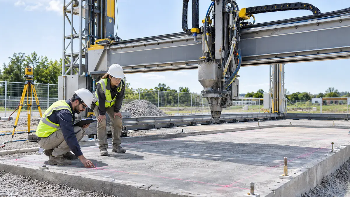
| 1. Mix and process qualification | The material can be mixed, pumped, deposited and stacked under the intended equipment and environmental conditions. | Approved materials and proportions, fresh-state tests, trial prints, printer settings, layer geometry, open-time limits and process controls. |
| 2. Hardened-material and wall verification | Printed material, interfaces, connections and the complete wall system meet the properties required by the approved design and applicable requirements. | Representative specimens, compression/tension/flexure/shear tests as specified, durability evidence, system qualification and inspection records. |
Project testing frequencies, witness points, specimen counts, acceptance limits and release authorities must come from the approved design, specification, applicable regulations and qualified printing system. They should not be borrowed from a generic internet mix recipe or a conventional concrete specification without review.
Is there a special mix design for concrete printing?
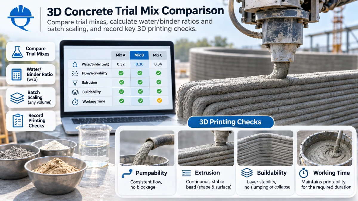
Yes. A 3D-printable cementitious mix must be workable enough for transport through the pump and nozzle, but develop sufficient green strength or structural build-up to support later layers. Many systems use fine aggregates, carefully controlled water and admixtures, although printable mixes and maximum aggregate sizes vary significantly among printers.
Which fresh properties should be checked?
- Pumpability: the mix travels through the delivery system without unacceptable pressure, blockage or segregation.
- Extrudability: material exits the nozzle consistently as a bead with controlled continuity and geometry.
- Buildability: newly deposited layers support subsequent layers without unacceptable spreading, deformation or collapse.
- Working or open time: the mixture remains printable over the required production interval while maintaining suitable interlayer contact.
- Rheological development: flow resistance and structural build-up change with time, temperature, shear history and material chemistry.
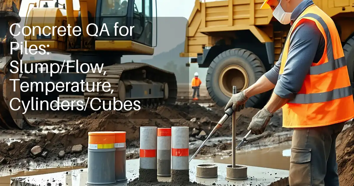
Slump, mortar flow, temperature and other conventional fresh-state checks may be useful where the applicable material and approved procedure make them relevant. However, a passing slump or flow test is not, by itself, proof of pumpability, buildability or layer bonding. Trial printing with the actual nozzle, equipment and production conditions is an important complementary verification.
The qualified mix must also remain consistent during production. Record binder, aggregate, water, admixture dosages, moisture corrections, mixing sequence, material age and any changes or adjustments. Unapproved additions can change both fresh behavior and hardened performance.
Existing Quollnet tool: QMix Designer — preliminary concrete proportions can help explain water–cementitious ratio, quantities and moisture correction. It is not a validated 3D-printable concrete mix designer and does not calculate extrusion, buildability or interlayer strength.
Which specimens represent the printed wall?
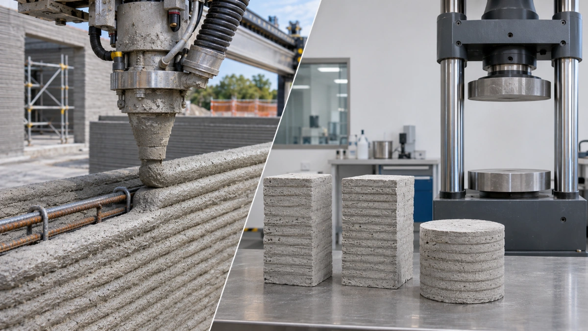
This may be the single most important testing-plan decision. The same mix can be cast in a mold, printed separately, or extracted from a printed element; those specimens do not necessarily provide interchangeable evidence.
| Specimen source | Useful for | What it may not prove |
|---|---|---|
| Cast cubes or cylinders | Conventional material-strength controls, batching consistency and comparison with the qualified mix. | Actual printed layer interfaces or process-induced weaknesses. |
| Separately printed specimens | Controlled assessment of printing effects and orientation. | Identical conditions to the production wall unless the process and timing match. |
| Specimens cut from trial or companion printed panels | Layer-interface behavior, directional properties and the approved qualification procedure. | Every location or connection in the finished building. |
| Cores or other samples from a constructed wall | Investigation of a specified as-built location when authorized. | Whole-wall acceptance on their own; extraction may disrupt layers or damage the element. |
When samples are extracted, record their parent element, exact position, printing direction, layer orientation, extraction and preparation method, dimensions, conditioning, curing and loading arrangement. A label such as “Wall 2 — Sample 4” is insufficient if the failure plane and printing history cannot be reconstructed.
Do not cut or core a structural printed wall solely to obtain a test sample without engineering authorization. Sample removal, reinforcement and cavity locations, repair requirements, and test representativeness need to be reviewed. NIST notes that companion walls and cut specimens are being used to address gaps in established test methods for additive construction.
How is compressive strength tested?
Compressive strength is still relevant to printed cementitious materials. A testing laboratory subjects a suitable specimen to increasing compressive load, determines the maximum load and calculates stress from the prescribed loaded area and test procedure.
For a conventional cylindrical specimen, ASTM C39/C39M is one established method. Other applicable methods may govern cubes, cores or special printed specimens. The test method must match the specimen, not merely its intended strength grade.
In printed concrete, engineers must also consider:
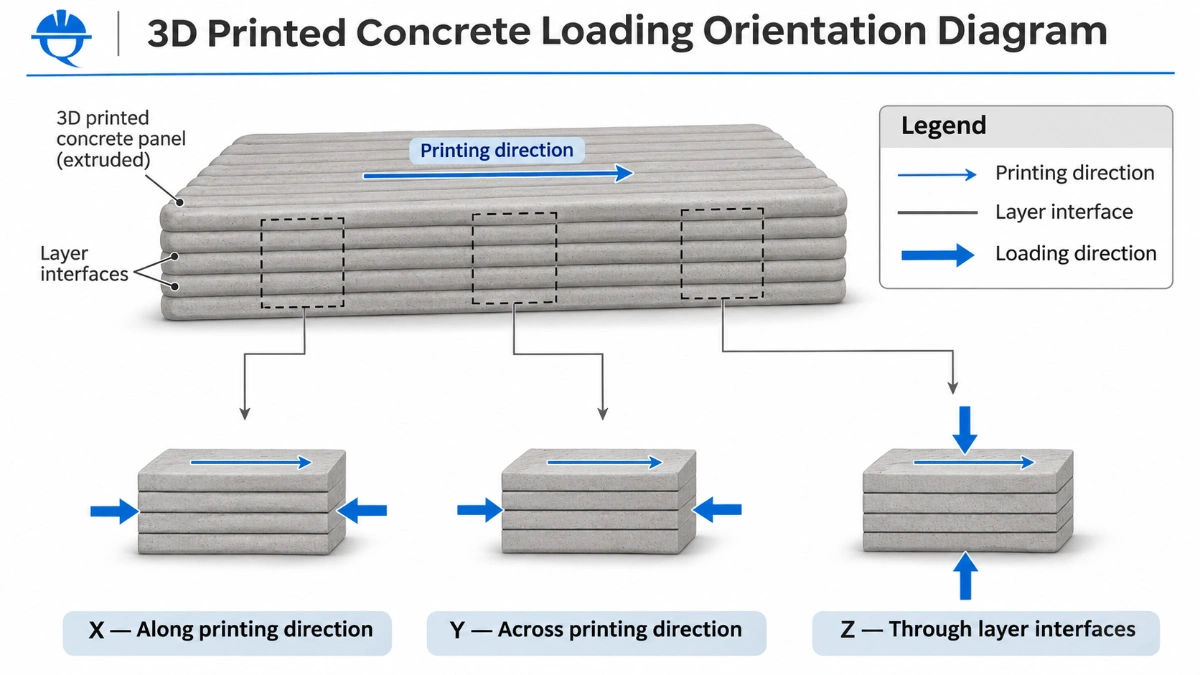
- Loading orientation: does the compressive load act in a direction that crosses layer planes or mainly runs along them?
- Specimen geometry: are layers, bead widths, voids, interfaces and dimensions adequately represented?
- Preparation: can sawing, grinding, drilling or end preparation affect the tested material?
- Curing and age: was the specimen conditioned comparably with the qualified procedure and production element?
- Interpretation: does the reported strength correspond to the property and direction required by the structural design?
RILEM's interlaboratory investigations explicitly examined compressive strength and modulus of elasticity, including the effects of extraction location, curing, scale and deliberately extended layer intervals. There is no justification for assigning an automatic universal conversion between cast-cylinder strength and every printed-wall strength condition.
Calculation aid: Concrete Strength Calculator — load, dimensions and MPa calculates arithmetic compressive strength for supported cubes and cylinders. It does not determine a printed specimen's orientation correction, interlayer adequacy or engineering acceptance.
How is interlayer bond strength tested?
Interlayer bond is a distinct property. It describes resistance to separation or relative movement across the interface formed when one deposited layer is placed against another. A high compressive result from cast specimens does not establish a satisfactory interlayer bond.
Depending on the approved qualification programme, researchers and specialist laboratories may use direct tensile loading, splitting-type tests, flexural tests with an intentionally oriented interface, or shear configurations. These methods do not necessarily measure an identical property. Specimen geometry, principal stress direction, loading rate, bonded area and failure mode matter to the interpretation.
Why can printing interruptions matter?
As the previously deposited layer stiffens, a delay before the next layer can alter contact and interfacial performance. Some interruptions may create a weak plane even when the material in each individual bead remains strong. Research across multiple printing systems has found that tensile behavior can be particularly sensitive when the principal tensile stress acts perpendicular to the layers.
Site reports should therefore identify the nominal and actual interval between layers, relevant environmental conditions, material age and whether the affected interface was part of the qualified process. An interruption outside the qualified procedure is a reason for investigation, not an invitation to assume the next layer is automatically acceptable.
For the field response to visible defects and interrupted printing, see the 3D Printed Concrete Defects — Visual Field Guide and the 3D printed concrete inspection guide.
What about tensile, flexural, shear and elastic-modulus tests?
Compressive strength is not the complete material characterization required for every application. Flexural performance, direct or indirect tensile response, interbead and interlayer shear resistance, and modulus of elasticity may influence design or qualification. Their relevance depends on whether the printed wall is bearing, nonbearing, reinforced, composite, or part of a qualified proprietary system.
A printed specimen may show a different response when the critical tensile stress crosses an interface rather than running parallel to the deposited layers. The RILEM TC 304-ADC studies compared three- and four-point bending, splitting and uniaxial tensile configurations across printed and cast materials. Results confirm that orientation and the chosen test configuration belong in the report.
The test programme should identify which properties are required, how they relate to the approved structural model, and whether any results are for preliminary research, process qualification or contractual acceptance. Do not convert a research-study trend into a universal design reduction factor.
When are durability and full-system tests needed?
Durability testing may be necessary where specified exposure conditions raise questions about moisture ingress, permeability, shrinkage, freeze-thaw resistance, chemical attack or other long-term mechanisms. Layer interfaces, internal cavities and printed-to-conventional junctions may introduce pathways or details that are not reflected by a single bulk-material sample.
Where applicable, the approved programme may also require fire, thermal, connection, reinforcement or larger-scale structural performance evidence. Such tests should assess the relevant wall assembly and system, not only an isolated printable mortar.
ICC 1150-2026 addresses minimum requirements for materials, qualification, inspection and structural design of 3D concrete wall systems. Its application depends on the project jurisdiction and adopted requirements. ISO/ASTM 52939:2023 provides process-oriented quality-assurance principles for additive construction but explicitly does not establish material-property characterization or testing; the two references serve different purposes.
Test matrix: what each result can—and cannot—tell you
| Check or test | Primary question | Important limitation |
|---|---|---|
| Flow/workability and material age | Is the fresh material within the defined operating condition? | Does not alone demonstrate extrusion or buildability. |
| Trial print and bead geometry | Can the mix and printer maintain the required process? | Does not establish final structural strength. |
| Cast specimen compression | What strength does this cast material specimen achieve? | Cannot alone verify printed interfaces. |
| Printed specimen compression | What is the behavior in the documented test orientation? | May not represent other orientations or wall details. |
| Interlayer tension or shear | How does the interface resist the specified loading mode? | Method-specific result; not automatically interchangeable. |
| Durability or system performance | Does the material or assembly meet its exposure/performance requirement? | Must match the actual wall configuration and exposure. |
How should a site engineer decide whether results are acceptable?
Acceptance begins with a defined criterion, not a test value. Before printing, the engineer and project QA/QC team should know which document sets each requirement and whether the test has been approved for the specific printed material or wall system.
- Confirm the approved basis: design drawings, specification, qualified system documents, applicable standard and inspection/test plan (ITP).
- Confirm representativeness: material batch, print segment, specimen source, orientation, sampling location, age and curing history.
- Check laboratory validity: appropriate method, specimen dimensions, conditioning, machine calibration, test setup and observed failure mode.
- Compare like with like: use the actual specified property, specimen basis, direction, age, statistic and acceptance rule; do not substitute a cast-specimen result for an interlayer criterion.
- Investigate deviations: distinguish an invalid or unrepresentative test from a potential material/process or structural nonconformance.
- Record disposition and release: obtain the required engineer/consultant decision, corrective measures and retesting or verification before closing a hold point.
Where a result is low, check specimen identification, test validity, curing and exposure, printing history and the relevant direction before deciding what it means for the wall. The appropriate action could be further evaluation, approved additional testing, localized repair, design assessment or rejection—depending on severity and the governing documents. A nonconformance report records a deviation; it is not prior permission to continue defective work.
Our existing guides on investigating low concrete strength and concrete core testing help explain general investigations, but conventional concrete acceptance rules must not be transplanted into a printed-wall assessment without engineering validation.
Field example: a test result linked to an actual print segment
Consider an illustrative site situation: a printer pauses while constructing a load-bearing wall, then resumes. A later laboratory report shows satisfactory compressive strength in a cast specimen. The site record nevertheless identifies a layer interval outside the qualified process window.
The cast result does not resolve the interface concern. The responsible engineer should review the actual interval and environmental/material history, confirm which interface properties are required, assess whether qualified testing or other evidence covers the deviation, and decide the documented disposition before acceptance or concealment.
A traceable specimen and test register should capture at least the following:
| Record field | Evidence to retain |
|---|---|
| Element and print file | Project, wall/segment, approved model and print-path revision |
| Mix and batch | Approved mix ID, material batch, mixing and extrusion time |
| Process history | Nozzle/print configuration, layer interval, interruption, site conditions |
| Specimen provenance | Sample ID, location, orientation, preparation, dimensions, age and curing |
| Test and evidence | Lab, procedure, loading arrangement, result, failure mode, report reference |
| Disposition | Specified criterion, review outcome, approver, action, retest and release |
A quality record is useful only if its identifiers connect the laboratory result back to the actual printed location and process history. See the before-, during- and after-printing inspection guide for focused field checklists that complement the test programme.
Practical Quollnet tools: which ones can help?
Quollnet has useful conventional concrete calculation and recordkeeping tools. They can support parts of the workflow, but they do not automatically qualify a 3D-printing mix, calculate interlayer bond or certify a printed wall.
QMix Logbook — batch and test recordkeeping
Track batches, specimen IDs, dates and conventional test results with exports. Its current concrete-pour fields are not a dedicated 3D-printing specimen-orientation or print-process register.
QMix Auditor — material quantities and water ratio
Review batch quantities, aggregate moisture and effective water–cementitious ratio. Its conventional strength estimates should not be interpreted as validated predictions for printed-wall performance.
Concrete Strength Calculator — conventional specimen arithmetic
Calculate compressive stress from documented load and geometry where the specimen and method are appropriate. Engineering acceptance remains a separate decision.
For process-specific inspection and test sequencing, the existing 3D concrete printing Inspection & Test Plan is an example to review and adapt—not a substitute for the project's approved ITP.
Continue through the 3D-printing inspection cluster
3D Printed Concrete QA/QC: Inspection, Process Control & Acceptance — establish the qualification and inspection framework.
3D Printed Concrete Defects: Visual Field Guide — recognize defects and decide what to record or investigate.
3D Printed Concrete Inspection Checklist: Before, During & After Printing — access five visit-specific, interactive QChecklists.
Concrete Compressive Strength Testing: Cubes, Cylinders & Acceptance — understand conventional laboratory fundamentals before adapting them to printed specimens.
Bottom line: Test the mix, test the printing process, test representative printed material, and verify the complete wall system against documented requirements. The value of a result depends as much on specimen provenance and test orientation as on the number reported by the laboratory.
References
ICC 1150-2026 — Standard for 3D Automated Construction Technology for 3D Concrete Walls
International Code Council — ICC 1150 committee and publication information
ISO/ASTM 52939:2023 — Additive manufacturing for construction: Qualification principles
NIST — Assuring the Long-Term Performance of Additively Constructed Structures
NIST — Cementitious-material extrusion and time-dependent rheology research
RILEM TC 304-ADC — Interlaboratory study: Approach and main results (2025)
RILEM TC 304-ADC — Compressive strength and modulus of elasticity (2025)
RILEM TC 304-ADC — Flexural and tensile strength (2025)
ASTM C39/C39M-26 — Compressive Strength of Cylindrical Concrete Specimens