Concrete Core Testing: When to Drill, How to Test and How to Interpret Results
A concrete core test is an in-place strength investigation tool, not an automatic retest after every low cube or cylinder result. First confirm that the original acceptance criterion was actually breached and that the laboratory test is valid. If cores are justified, select locations deliberately, obtain and test them under the applicable standard, and interpret the results using the governing code or approved assessment procedure rather than a universal core-to-cylinder conversion factor.
A core test asks a different question from a standard-cured cube or cylinder test: it samples concrete that is already inside the structure so the engineer can assess the strength of the concrete actually placed in the area of concern.
When is a concrete core test justified?
Concrete cores are normally considered when the project needs direct information about hardened concrete in the structure. Typical triggers include a sufficiently low standard-cured strength test, doubt about the quality of concrete in a particular location, visible distress, questionable construction history, or an assessment of an existing structure.
Core drilling should not be the first reaction to a disappointing number. Before any destructive investigation, verify the governing acceptance rule and the original test. The companion article Concrete Compressive Strength Acceptance Criteria: ACI 318-25 vs EN 206 explains why one low specimen does not automatically equal a failed strength test.
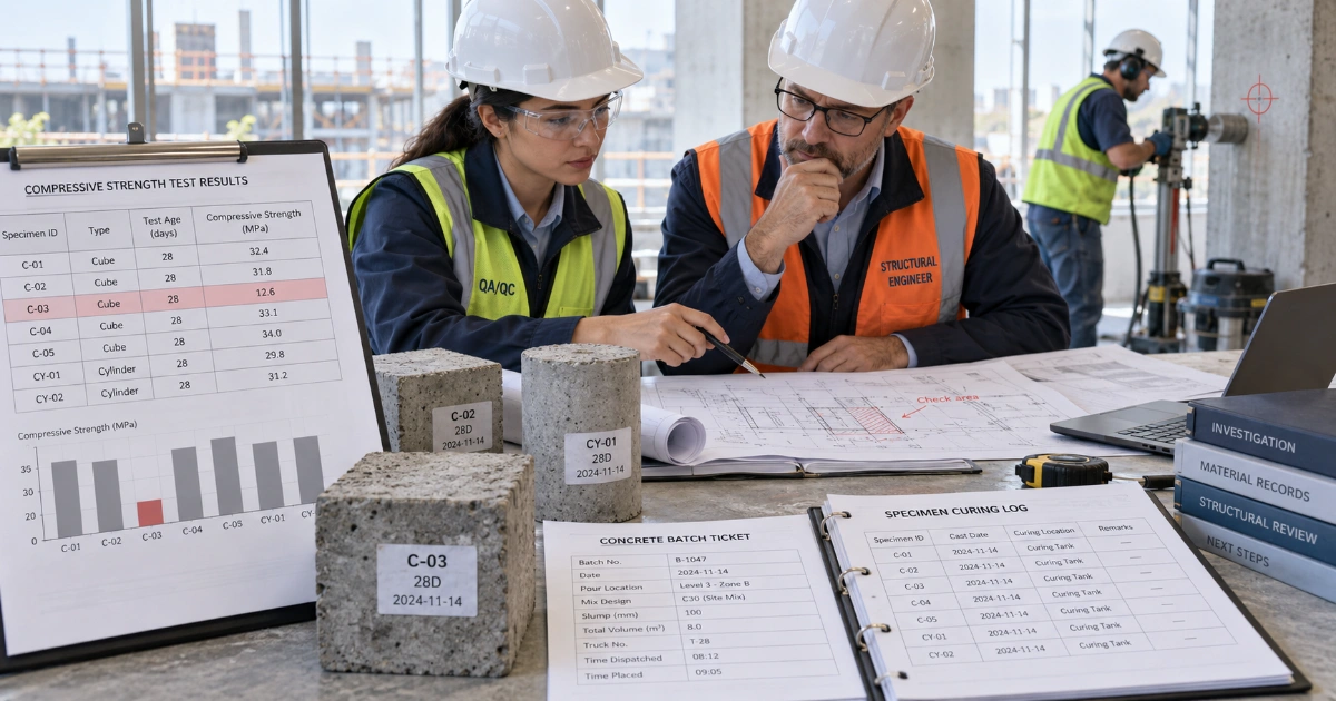
If the acceptance criterion is not met, first follow a structured low-strength investigation. Review specimen identity, curing, test age, laboratory records, batch traceability, placement location and related results. See Low Concrete Compressive Strength: What to Do Before You Reject the Concrete.
What ASTM C42 actually does
ASTM C42/C42M-20 is the current active ASTM method for obtaining, preparing and testing drilled concrete cores. It standardizes the physical core-testing process. It does not establish one universal acceptance value for every structure or every investigation.
ASTM C42 is used because the measured core strength can be influenced by several factors beyond the concrete's intrinsic strength, including where the core came from, its dimensions, moisture history and preparation. The test therefore needs a defined sampling and preparation procedure rather than simply drilling a cylinder-shaped piece of concrete and putting it in a compression machine.
ASTM C42 explicitly notes that there is no universal relationship between core strength and the strength of corresponding standard-cured cylinders. The familiar 85% figure appears in a specific ACI acceptance pathway; it does not mean that every core should physically equal 85% of a cylinder result.
Who should decide where the cores are drilled?
Core locations should be selected to answer the engineering question, not simply because they are convenient to drill. The selected cores need to represent the concrete of concern while avoiding unnecessary damage to the member.
Before drilling, the investigation should define:
- the structural member and region represented by the low or uncertain result;
- the number and distribution of proposed cores;
- whether the chosen locations are reasonably representative;
- reinforcement, prestressing tendons, embedded services and other items that must not be damaged;
- the core diameter and target length;
- how each hole will be repaired after testing; and
- the acceptance or assessment procedure that will be applied to the results.
A rebar scanner or other appropriate locating method should be used before drilling. Core extraction should not cut reinforcement or prestressing unless the responsible structural professional has explicitly assessed and approved it.
Core location can influence the measured strength
Concrete within one structural element is not perfectly uniform. Placement, bleeding, consolidation, temperature and moisture history can vary through the member. ASTM guidance notes that concrete strength can vary with location, including vertical position in a member.
That means a core result is not meaningful without its exact location. Record the element reference, grid or coordinates, elevation, drilling direction and relationship to the original pour or batch. A core marked only as “Core 1” loses much of its investigative value.
How a concrete core is obtained and prepared
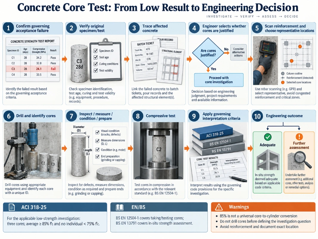
The exact procedure should follow ASTM C42/C42M or the applicable project standard, but a controlled core-testing workflow normally includes:
- Confirm the investigation plan. Define what the cores are intended to establish before drilling starts.
- Locate reinforcement and services. Mark safe drilling positions and any prohibited zones.
- Identify each location. Give every proposed core a unique reference linked to the structural drawing.
- Diamond drill the core. Use controlled equipment and collect drilling water and slurry.
- Inspect the extracted core. Record defects, embedded material, damage and orientation where relevant.
- Measure the specimen. Record diameter, length and other dimensions required by the test method.
- Condition and prepare the ends. Follow the specified procedure before compression testing.
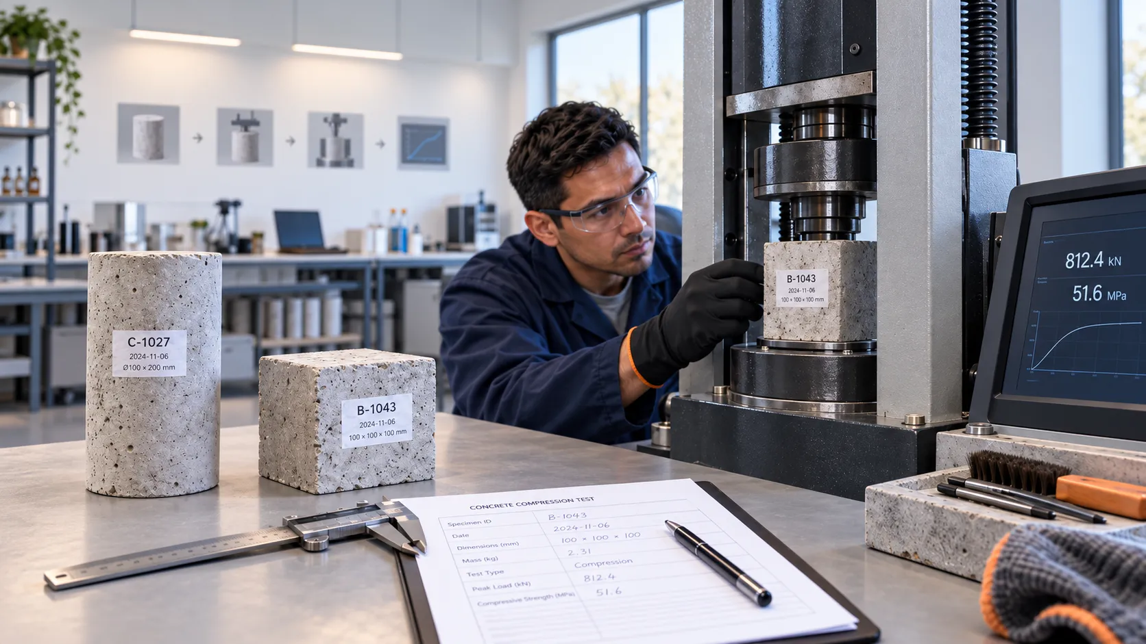
- Test in compression. Apply the appropriate loading procedure and record the maximum load and calculated strength.
- Report the result with its location. A core strength without traceability to the structure is incomplete evidence.
What core diameter should be used?
Core diameter affects both representativeness and test variability, especially when the coarse aggregate is large relative to the specimen. Under ASTM C42/C42M-20, a core used for compressive-strength testing should have a diameter of at least 94 mm (3.70 in.) or twice the nominal maximum coarse-aggregate size, whichever is larger, unless the standard's documented exception is justified because the member thickness or reinforcement makes that size impracticable.
In practical investigation work, nominal 100 mm (4 in.) cores are therefore common and generally preferable to very small-diameter cores. ASTM notes that nominal 50 mm cores tend to show greater variability than nominal 100 mm cores.
BS EN 12504-1:2019 also recognizes the effect of aggregate size relative to core diameter. Its guidance treats the ratio between core diameter and the upper aggregate size as an important source of variability when the ratio becomes small. As a practical planning target, a diameter around three times the maximum aggregate size is desirable where the structure allows it, but this should not be presented as a universal hard minimum overriding the governing standard, reinforcement layout or investigation plan.
Do not choose the smallest drill merely because it is easier to use. Core diameter should be selected before drilling with aggregate size, reinforcement spacing, member thickness, expected variability and the governing test standard in mind.
Why length-to-diameter ratio matters
A drilled core is not automatically the same geometry as a standard cylinder. The apparent compressive strength is affected by the core's length-to-diameter ratio, commonly written as L/D. Shorter specimens can show a higher apparent strength because platen restraint influences a larger proportion of the specimen, so ASTM C42 controls both specimen geometry and the correction applied to shorter cores.
For the normal ASTM C42 compressive-strength route, a prepared core with L/D below 1.00 is not tested. For cores with 1.00 ≤ L/D ≤ 1.75, the measured compressive strength is multiplied by the applicable correction factor. Above 1.75, no L/D correction is required.
| ASTM C42 L/D | Strength multiplier |
|---|---|
| 1.75 | 0.98 |
| 1.50 | 0.96 |
| 1.25 | 0.93 |
| 1.00 | 0.87 |
For intermediate L/D values, use the interpolation procedure required by ASTM C42 rather than rounding to the nearest row. The correction belongs to the laboratory calculation and should be reported transparently.
ASTM C42 permits cores prepared at approximately L/D = 1.00 to 1.05 when core strengths are being compared with specified cube strength; the normal L/D correction factor is not applied in that comparison. EN/BS practice likewise distinguishes core geometry used for cylinder-strength and cube-strength comparisons. Do not apply the ASTM table mechanically without first confirming the strength basis being assessed.
Do not invent a site correction because a core is “a bit short.” Measure and report the specimen correctly and apply only the correction procedure allowed by the governing test standard.
Why moisture conditioning matters
Core moisture condition can change the measured compressive strength. For that reason, conditioning is part of the test procedure rather than a cosmetic laboratory choice.
The project should identify the required conditioning route and the laboratory should record what was actually done. Comparing one set of cores tested under one moisture condition with another set conditioned differently can introduce avoidable uncertainty.
Core strength is not the same as standard-cured cube or cylinder strength
A standard-cured specimen is made from a fresh concrete sample and cured under controlled conditions. A core is removed later from concrete that experienced the actual placement, consolidation, temperature, moisture and structural environment.
Those are fundamentally different specimen histories. Geometry also differs. This is why a direct universal conversion is not defensible.
The same caution applies when comparing cube and cylinder systems. See Concrete Cube vs Cylinder Strength: Why the 0.8 Rule Can Mislead.
ACI 318-25: when cores are used after a low strength test
Under ACI CODE-318-25, the low-strength investigation provisions are in Section 26.12.7. The investigation becomes relevant when the applicable individual-strength-test lower limit is breached or when another code-permitted investigation requires assessment of in-place strength.
ACI does not say that every low individual cylinder should trigger drilling. First establish that the defined strength test and the governing acceptance criterion actually failed.
For the underlying standard-cured acceptance rules, see Concrete Compressive Strength Acceptance Criteria: ACI 318-25 vs EN 206.
ACI 318-25 core strength acceptance criteria
When the ACI low-strength investigation uses three cores, ACI 318-25 states that the concrete represented by those cores is considered structurally adequate when both of the following are satisfied:
- The average strength of the three cores is at least 85% of \( f'_c \).
- No individual core is below 75% of \( f'_c \).
These percentages are acceptance thresholds within this ACI investigation. They are not a claim that a core from satisfactory concrete should normally equal exactly 85% of a standard-cured cylinder.
Example: \( f'_c = 40\text{ MPa} \)
For an ACI investigation using the three-core criterion, the average of the three cores would need to be at least:
\[0.85 \times 40 = 34\text{ MPa}\]and no individual core could be below:
\[0.75 \times 40 = 30\text{ MPa}\]The calculation is simple; the difficult part is making sure the cores genuinely represent the concrete being assessed and were obtained and tested correctly.
What if the three ACI cores do not satisfy 85% / 75%?
Do not turn the result into an automatic demolition decision. A failed core criterion means the responsible structural professional must continue the assessment using the governing code, structural demand, location of the low concrete and other evidence.
Possible next steps can include additional investigation where justified, structural analysis, load restrictions, strengthening, repair, partial replacement or other approved dispositions. The correct response depends on the member, actual demand, extent of the affected concrete and contractual framework.
BS EN 12504-1 and BS EN 13791: the EN/BS route
The EN/BS system separates the physical core test from the broader in-situ strength assessment.
| Standard | Primary role |
|---|---|
| BS EN 12504-1:2019 | Taking, examining, preparing and compression-testing concrete cores. |
| BS EN 13791:2019 | Assessment of in-situ compressive strength in structures and precast concrete components. |
BS EN 12504-1 itself does not tell the engineer whether cores should be drilled, where they should be drilled, or how the results prove structural adequacy. BS EN 13791 provides the assessment framework for in-situ compressive strength. Project specifications and national provisions still need to be checked.
Do not import the ACI 85% / 75% criteria into an EN/BS project unless the contract explicitly adopts that approach.
Can rebound hammer or ultrasonic testing replace concrete cores?
Indirect methods can be useful for mapping variability and helping select investigation areas, but they do not automatically provide the same evidence as a drilled core. Their relationship with in-situ compressive strength must be established and interpreted under the applicable assessment procedure.
BS EN 13791 specifically addresses the use of in-situ test data and relationships with indirect measurements. An indirect test can therefore support the investigation without becoming an unqualified substitute for direct core strength.
Common mistakes during a concrete core investigation
- Drilling immediately after one low cylinder. First verify whether the actual acceptance criterion failed.
- Choosing only convenient locations. Convenience can create a biased sample.
- Cutting reinforcement. Scan and approve locations before drilling.
- Losing orientation or location traceability. Every core must remain linked to the structure.
- Ignoring L/D and conditioning. Both can influence the measured result.
- Treating 85% as a conversion factor. It is an ACI acceptance threshold in a defined pathway.
- Mixing ACI and EN/BS criteria. Use the system adopted by the project.
- Looking only at the laboratory number. The engineering meaning depends on where the core came from and what question the investigation is answering.
What should the concrete core test report contain?
A useful core report should allow another engineer to understand exactly what was sampled and how the result was produced. Record at least:
- project and structure identification;
- member and exact core location;
- core ID and drilling orientation;
- date of drilling and date of testing;
- core diameter and tested length;
- observed reinforcement, voids, cracks or unusual features;
- specimen preparation and moisture conditioning;
- maximum load and reported compressive strength;
- any standard-permitted correction applied;
- photographs before drilling, after extraction and of the prepared core;
- reference to the governing ASTM/EN test standard; and
- the engineering assessment or acceptance basis, kept distinct from the raw laboratory result.
Practical concrete core test workflow
Confirm the acceptance failure → verify the original test → trace the affected concrete → decide whether in-place assessment is justified → define representative core locations → scan reinforcement → drill and identify cores → prepare and test under the applicable standard → apply the governing interpretation procedure → document the engineering disposition.
If the concern starts with the original cylinder or cube compression procedure, review How to Perform a Concrete Compressive Strength Test: Cubes & Cylinders before escalating to destructive testing.
References
ACI CODE-318-25 – Building Code for Structural Concrete—Code Requirements and Commentary
Concrete International, January 2026 – Acceptance Testing of Field-Cured Cylinders Q&A