Concrete Compressive Strength Testing: How to Test Cubes and Cylinders Correctly
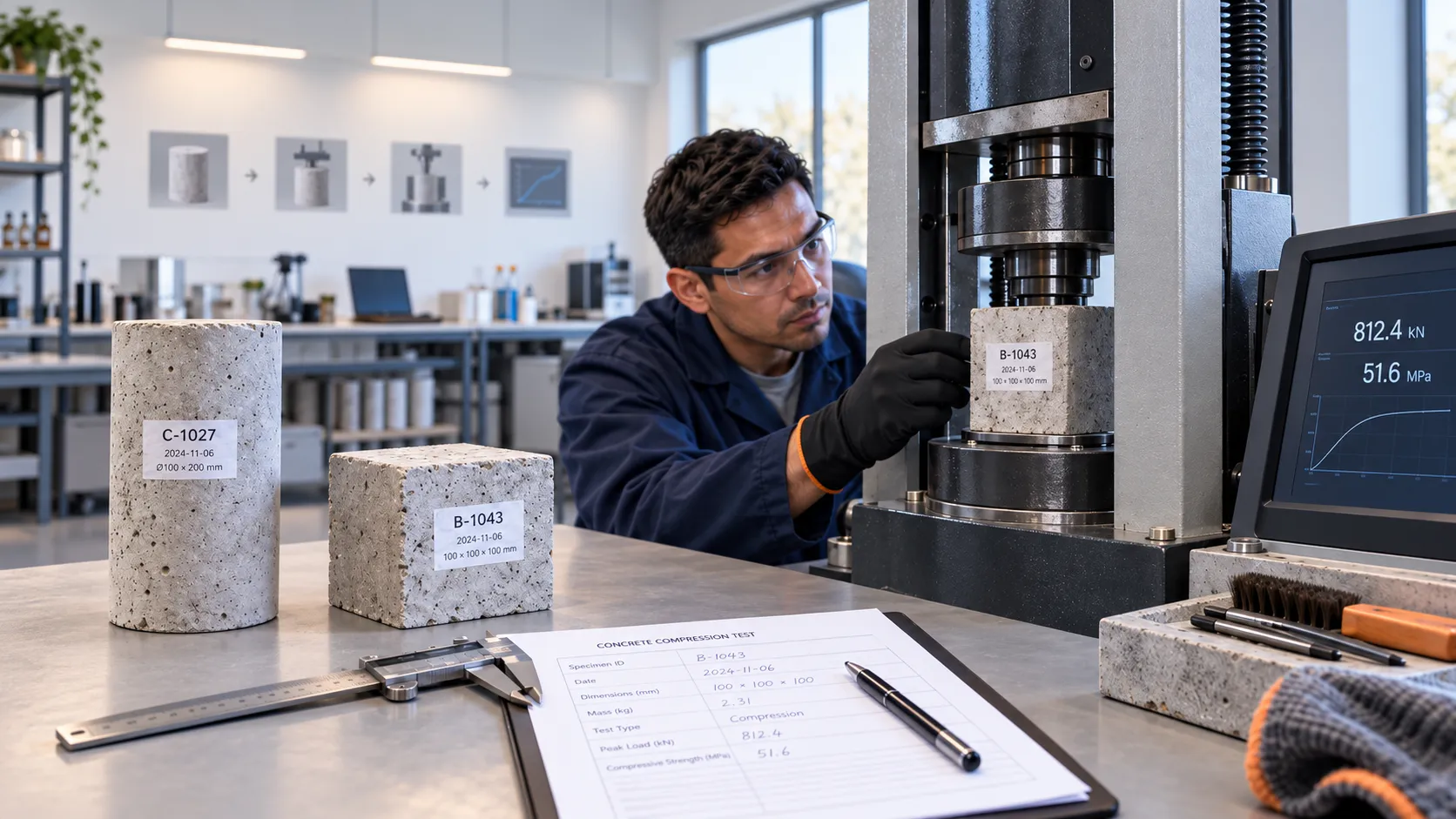
Concrete compressive strength testing measures the maximum compressive stress a hardened cube or cylinder can sustain before failure. The practical sequence is simple—identify the specimen, confirm age and condition, center it correctly, apply load under the governing test method, record the maximum load, calculate strength from the loaded area, note the failure appearance, and report the individual result separately from the project acceptance decision.
- Cube vs cylinder: do not treat the results as directly interchangeable. Specimen geometry and the governing test system affect the measured strength.
- Record raw load first: retain the maximum machine load in kN or N, the dimensions used for area, and the calculated MPa result. Machine software should not be the only audit trail.
- End condition matters: unsuitable bearing faces, poor cylinder end preparation or damaged caps/pads can distort load transfer and make a result questionable.
- Failure appearance is evidence: note unusual shear, splitting or local crushing, but do not delete or rewrite the original result to make an average look cleaner.
Compressive strength = maximum load ÷ loaded cross-sectional area
With load in newtons and area in mm², the result is N/mm², numerically equal to MPa.
Calculate cube or cylinder strength
Use the calculator for the arithmetic, then keep the raw maximum load and specimen dimensions in the laboratory record. The calculator does not decide whether the concrete is accepted.
Concrete Strength Calculator
Enter specimen dimensions and maximum load to calculate compressive strength.
P = 900 kN × 1000 = 900,000 N
A = 150 × 150 = 22,500 mm²
f_c = 900,000 / 22,500 = 40.00 MPa
Calculation aid only. Concrete acceptance depends on the project specification, specimen/test standard, curing, test age and applicable acceptance criteria.
Record the original maximum machine load and specimen dimensions with the calculated MPa result.
What does a concrete compressive strength test actually measure?
The compression machine applies an axial load to a prepared hardened-concrete specimen until the specimen can no longer sustain the load. The maximum load is divided by the loaded cross-sectional area to obtain the reported compressive strength.
The result is not independent of the test system. Sampling, specimen making, curing, test age, moisture condition, geometry, end condition, machine setup and loading procedure can all influence the measured strength. That is why the test record should preserve enough information to reconstruct how the number was obtained.
Cube test vs cylinder test
| Item | Concrete cube | Concrete cylinder |
|---|---|---|
| Typical test route | BS EN 12390-3 / EN-based systems | ASTM C39/C39M / ASTM-based systems |
| Area used | Loaded face area | Cross-sectional area from the measured diameter |
| Important preparation issue | Correct loaded faces and orientation | Approved end preparation and uniform bearing |
| Can the results be directly converted? | No. Use the cube-strength requirement defined by the project. | No. Use the cylinder-strength requirement defined by the project. |
Cube and cylinder specimens do not develop identical stress conditions under the platens. If a project specifies cylinder strength, do not substitute cube results using an assumed universal conversion, and vice versa.
Before the specimen goes into the machine
A technically correct compression cycle on the wrong specimen still produces a useless quality record. Verify the specimen before testing:
- specimen ID and link to the correct sample, mix, truck/load and pour location;
- required test age and actual test age;
- whether the specimen was standard-cured or field-cured;
- dimensions required for the strength calculation;
- visible damage, chipped edges, irregular bearing surfaces or identification problems;
- the correct test method for the project; and
- compression-machine suitability and current calibration/verification status.
If the specimens came from a ready-mix delivery, traceability should start with the fresh-concrete sample. The Fresh Concrete Sampling Checklist shows the upstream chain from the delivery to later cube or cylinder records.
Step 1: inspect dimensions and bearing surfaces
Use the specimen dimensions required by the selected method. The loaded surfaces must allow reasonably uniform bearing. For cylinders, the ends require an approved end-preparation system so that load is transferred across the intended cross-section.
Under ASTM C39/C39M, cylinder testing works with referenced end-preparation practices such as capping or permitted unbonded-cap systems. Do not improvise an end condition because the specimen merely looks flat.
Step 2: clean the platens and center the specimen
Remove loose material from the machine bearing surfaces and specimen contact faces. Center the specimen so the applied load acts through the intended axis. Poor centering can create eccentric loading and an abnormal fracture pattern.
For cubes, use the orientation required by the governing test method and laboratory procedure. For cylinders, center the specimen under the spherical-seated bearing block in accordance with the applicable ASTM procedure.
Step 3: load continuously to failure
Apply load using the rate and control method required by the selected standard. Avoid shock loading and arbitrary interruptions. Visible cracking can start before the specimen reaches its maximum load, so the test is not normally stopped at the first crack.
The critical machine value is the maximum load sustained by the specimen. Preserve that raw value even when the machine automatically converts it to MPa.
Step 4: calculate and retain the raw data
Use the measured loaded area and maximum load required by the governing method. For a cube, the loaded area is based on the loaded face dimensions. For a cylinder, area is calculated from the measured diameter using πd²/4.
Specimen dimensions → loaded area → maximum load → calculated MPa.
For example, a 150 mm × 150 mm loaded cube face has an area of 22,500 mm². If the maximum recorded load were 900 kN, the calculated strength would be 40 MPa. This is an arithmetic example, not a project acceptance value.
Step 5: read the failure appearance as a diagnostic clue
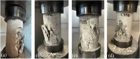
The fracture pattern can help identify whether the specimen behaved normally or whether specimen preparation, centering, bearing conditions or other factors should be reviewed. Failure appearance is a diagnostic clue, not a standalone proof of one specific cause.
| Failure appearance | What you may see | What to check |
|---|---|---|
| Generally satisfactory cone / split pattern | Distributed cracking and crushing rather than one highly localized break | Record the observed failure pattern and retain the result normally unless another test issue is present |
| Side shear / corner-dominated break | Strong diagonal or one-sided fracture | Centering, specimen alignment, bearing surfaces, visible specimen defects and machine setup |
| End splitting / local bearing failure | Cracking or crushing concentrated close to a loaded end or bearing face | Cylinder end preparation, cap or unbonded pad condition, platen cleanliness, flatness and uniform bearing |
Photograph or describe unusual failures when your laboratory procedure requires it. The important data-integrity rule is simple: do not delete an unexpected result because the fracture looks unusual. Preserve the raw result, add the observation, and refer the specimen for technical review where required.
Step 6: report each specimen result before applying acceptance rules
A useful compression-test record normally includes:
- project and pour reference;
- sample and specimen ID;
- mix designation and supplier/load traceability;
- specimen type and measured dimensions;
- date made, date tested and actual test age;
- curing condition;
- test standard;
- maximum load;
- loaded area and calculated compressive strength;
- failure appearance or abnormal observations; and
- tester and laboratory identification.
For tracking multiple test sets across a project, the existing Concrete Cube Test Register Excel Format – PDF & Excel Sample provides the register/log layer above the individual laboratory result.
The machine result is not the project acceptance decision
The compression machine produces an individual specimen result. Concrete acceptance may depend on multiple specimens, a defined test result or average, specified strength, age, curing basis, statistical rules, the governing concrete code and the project specification.
Concrete compressive-strength acceptance criteria and low-strength investigation deserve their own treatment and will be covered separately in this article cluster.
Why casting and curing deserve separate articles
Result quality begins long before the compression machine. ASTM C31/C31M distinguishes standard-cured specimens used for acceptance and quality-control purposes from field-cured specimens used for purposes such as estimating in-place strength or checking curing effectiveness. Under the BS EN route, BS EN 12390-2 covers making and curing specimens before testing under BS EN 12390-3.
Poor mould filling, inadequate compaction, early drying, unsuitable initial storage, damaged transport or specimen mix-ups can all influence the eventual strength result. Those operations should therefore be controlled as separate QA/QC activities rather than hidden inside the machine-testing procedure.
Common concrete compressive-strength testing errors
- Testing the wrong specimen because identity was not checked.
- Testing at the wrong age without recording the actual age.
- Using unsuitable bearing faces or poor cylinder end preparation.
- Placing the specimen off-center.
- Using an incorrect or inconsistent loading procedure.
- Recording only MPa and losing the original maximum load.
- Failing to retain the dimensions used to calculate area.
- Ignoring unusual failure appearance.
- Treating cube and cylinder results as directly equivalent.
- Mixing the individual test record with the later acceptance decision.
Practical laboratory workflow
Identify specimen → confirm age and curing → inspect dimensions and bearing surfaces → confirm machine and test method → center specimen → load to failure → record maximum load → calculate MPa → record failure appearance → preserve the individual result → send for project acceptance review.
Where specimens originate from ready-mix deliveries, the Concrete Truck Arrival & Delivery Record Template can help maintain traceability between the truck/load, field tests and specimen IDs.
References
ASTM C39/C39M-26 – Standard Test Method for Compressive Strength of Cylindrical Concrete Specimens
ASTM C31/C31M-26b – Standard Practice for Making and Curing Concrete Test Specimens in the Field
BS EN 12390-3:2019 – Testing hardened concrete: Compressive strength of test specimens
BS EN 12390-2:2019 – Testing hardened concrete: Making and curing specimens for strength tests