Core Pile Defect Confirmation: Coring, UPV, Petrography
Definition: Core Pile Defect Confirmation guides engineers and inspectors to extract cores, run ultrasonic and petrographic tests, and document objective evidence for concrete pile defects, excluding remediation decisions or repairs.
- Plan coring locations, protect reinforcement, and document evidence with photos.
- Run UPV measurements and petrography to triangulate defect type and extent.
- Align methods with approved project specifications and authority requirements.
- Interactive, commentable, export-ready checklist with secure QR code.
Core Pile Defect Confirmation ensures suspected defects in concrete piles are verified using objective methods before any remediation is considered. This checklist focuses on concrete pile coring, ultrasonic pulse velocity (UPV) testing, and petrographic analysis to triangulate defect type and extent. It defines a clean, auditable workflow: plan sampling, extract representative cores, capture high-fidelity UPV data, and commission lab petrography. The scope excludes remediation methods, patch design, or structural strengthening, but it delivers the risk control you need—avoiding reinforcement strikes, biased sampling, damaged cores, or misinterpreted velocity results. Outcomes include traceable evidence, repeatable measurements, and defensible assessments aligned with approved project specifications and authority requirements. Use it on new builds, retrofits, or asset investigations to substantiate concerns like voids, segregation, microcracking, or alkali–silica reaction. Start in interactive mode to tick steps, add comments, and attach photos, then export to PDF/Excel with a QR-secured record.
- Execute a disciplined investigation sequence: plan test locations, extract correctly oriented cores, acquire calibrated UPV measurements, and commission petrography. The process provides traceable evidence to confirm defect presence, type, and extent while reducing sampling bias and avoiding reinforcement damage.
- Produce an auditable file: geotagged photographs, UPV logs, core IDs, chain-of-custody, and lab reports. Correlate visual core logs with velocity maps and microscopic petrography to distinguish material flaws from construction artifacts, enabling defensible conclusions per approved project specifications and authority requirements.
- Interactive online checklist with tick, comment, and export features secured by QR code.
Pre-Assessment & Planning
Core Extraction
Ultrasonic Pulse Velocity (UPV) Testing
Petrography & Lab Coordination
Data Analysis & Assessment
Documentation & Reporting
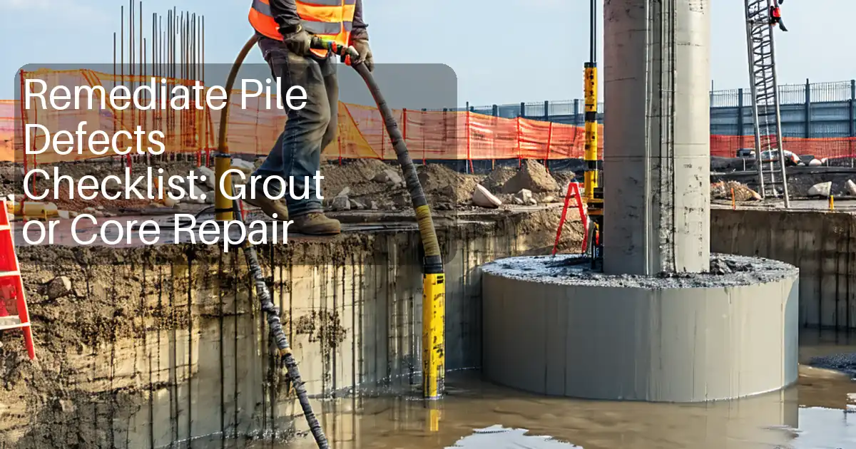
Plan Sampling and Extract Representative, Undamaged Cores
A robust confirmation program starts with a defensible sampling plan. Target zones where construction records or screening suggest anomalies, then verify reinforcement positions with a cover meter and GPR to minimize strike risks. Use a rigid, well-anchored coring rig and verify perpendicularity to limit induced microcracking. Continuous water cooling (approximately 2–4 L/min) maintains bit temperature and preserves the concrete matrix. Immediately mark top, bottom, and orientation on the core, then cap ends to reduce moisture loss and bias in petrography. Record depth to ±5 mm, location coordinates, and visible features such as voids or segregation. Chain-of-custody and temperature control (5–10 °C) protect sample integrity. On congested pile caps, plan smaller-diameter cores if specified and adjust to avoid bars while still sampling the suspect zone. Clear, time-stamped photographs of the hole, core, and setup accelerate later peer review and close-out.
- Scan reinforcement to avoid strikes and biased samples.
- Keep alignment within ±2° for clean, interpretable cores.
- Cap cores immediately; preserve moisture and orientation.
- Maintain 5–10 °C and complete chain-of-custody forms.
- Photograph location, core, and measurements with a scale.
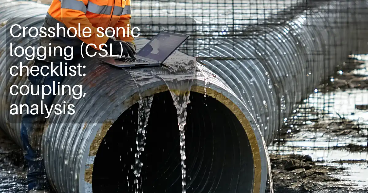
Acquire Reliable UPV Data and Interpret Patterns, Not Single Numbers
UPV supports coring by revealing relative stiffness changes and potential defects. Calibrate the instrument with its reference bar and verify time-of-flight accuracy. Prepare surfaces consistently, apply uniform couplant, and repeat each measurement to achieve a coefficient of variation at or below 3%. Use direct paths where possible; semi-direct or indirect paths are acceptable with careful documentation of geometry and path length. Map velocities in m/s across the pile length, then compare segments against control piles or adjacent sound concrete. Look for coherent low-velocity zones rather than isolated outliers. Temperature and moisture affect readings; log both and interpret trends within similar conditions. When velocity reductions exceed about 10% and align with core or petrographic evidence, treat the indication as credible for extent and severity mapping.
- Calibrate and verify before field readings.
- Repeat reads; target ≤3% variation per path.
- Document path type, spacing, and length precisely.
- Compare to control piles or sound segments.
- Correlate patterns with cores and petrography.
Use Petrography to Diagnose Mechanisms and Validate Extent
Petrographic analysis is the material microscope that explains UPV and core observations. Thin sections and stains can reveal paste quality, microcracks, deleterious reactions such as ASR, and compaction voids. To keep results valid, preserve moisture, avoid contamination, and ship promptly with full identifiers and photos of each core segment. Ask the lab to report magnifications, methods, and representative micrographs. Align the laboratory’s findings with field logs: for example, microcracking and debonded paste near a cold joint may explain a mapped low-velocity band. Use petrography to confirm mechanism and depth, not to estimate strength unless specifically requested. The combined evidence base supports a defensible assessment of defect type, extent, and likely origin without prescribing repairs, which are outside this checklist’s scope.
- Define objectives: paste, voids, microcracks, ASR.
- Protect moisture; seal and label immediately.
- Request clear images and signed lab reports.
- Correlate microstructure with UPV and core logs.
How to Use This Checklist
- Preparation: Assemble core drill and bits, coring rig, water supply, vacuum, UPV unit with reference bar, coupling gel, cover meter, GPR, metric scales, calibrated tapes, PPE, and permit/risk forms.
- Open the checklist in interactive mode on a tablet or laptop; select the project, piles, and intended tests; assign roles and due dates for field and lab tasks.
- During fieldwork, tick items as completed, add time-stamped comments, and attach geotagged photos, scans, and instrument screenshots directly to the relevant step.
- Record measurements in SI units within the step fields (e.g., core diameter, UPV m/s, temperatures); link files to pile IDs and locations for rapid retrieval.
- Export the checklist and evidence as PDF/Excel for review; share the QR-secured link with stakeholders to verify authenticity and dataset integrity.
- Sign-Off: Collect digital signatures from the inspector, engineer, and lab representative; archive the approved package in the project folder and lock edits.

Call to Action
- Start Checklist Tick off tasks, leave comments on items or the whole form, and export your completed report to PDF or Excel—with a built-in QR code for authenticity.
- Download Excel - Core Pile Defect Confirmation
- Download PDF - Core Pile Defect Confirmation
- View Image - Core Pile Defect Confirmation
Cite & Embed
“Core Pile Defect Confirmation by Quollnet”
with a link to
this source page.
FAQ
Question: What core diameter and length should I specify for defect confirmation?
Question: Can UPV alone confirm a defect without coring or petrography?
Question: How do I avoid hitting reinforcement while coring piles?
Question: How quickly can petrographic results be obtained, and how should samples be handled?
Question: What velocity reduction threshold indicates a likely defect in UPV testing?
Related Articles
Broader reading and guidance connected to this checklist topic.


Improve Your Project Handover Process With Snag List Tracking App


Related Checklists
Keep the workflow moving with nearby templates chosen from similar checklist content.