Designing Concrete for 3D Printing: What Makes a Mix Actually Printable?
Quick Answer: A 3D printable concrete mix must do more than achieve a target strength: it must pump through the equipment, extrude consistently, retain its shape under subsequent layers, and maintain adequate bonding within the qualified printing window. Mix design therefore combines material proportions, rheological behavior, printer settings, trial-print results, and hardened-performance testing. There is no universal recipe or single slump value that proves printability.
The engineering challenge: The material should flow when the pump and nozzle apply shear, then build enough resistance after deposition to hold the next layers. Improving one behavior can compromise another. A printed wall also needs qualified mechanical, interlayer and durability performance—not only a mix that looks good at the nozzle.
How is 3D printable concrete different from ordinary concrete?
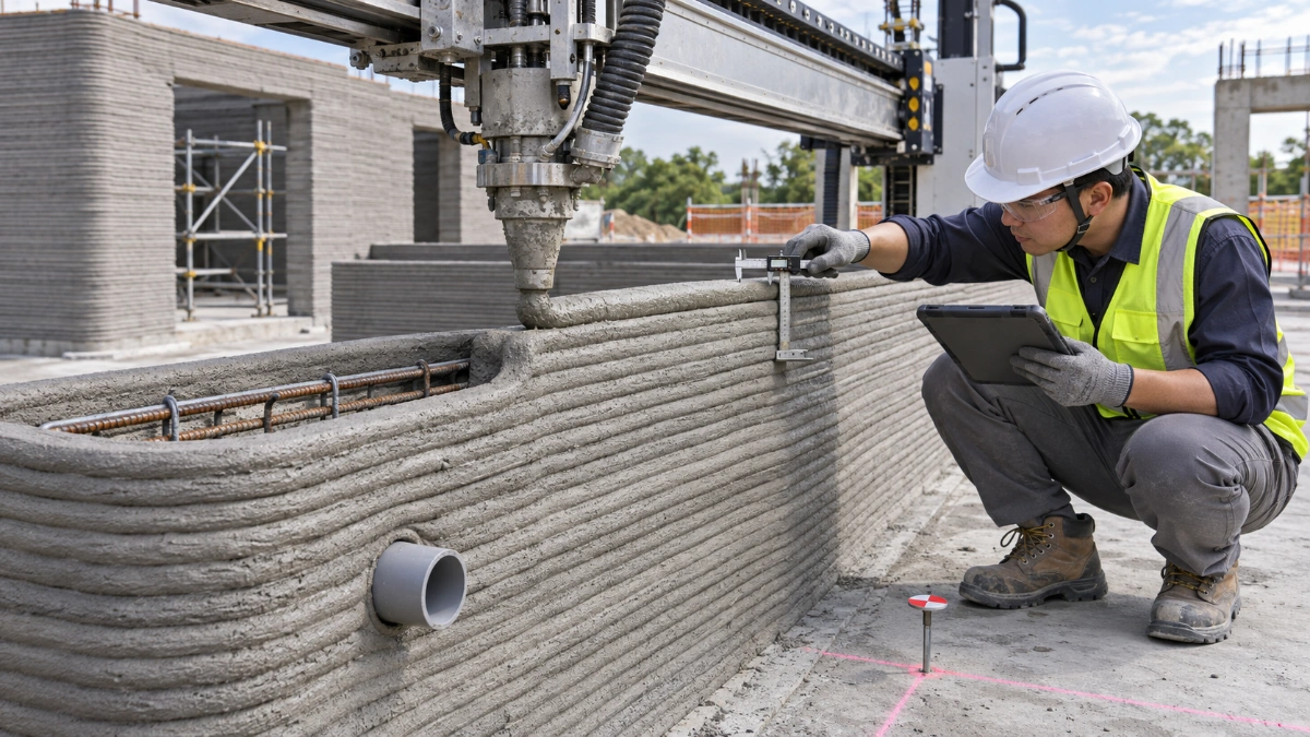
Conventional concrete is generally delivered into formwork, consolidated or allowed to flow as appropriate, and supported while it hardens. In extrusion-based 3D concrete printing (3DCP), a pump moves the mixture through a delivery line and nozzle; the printer places a continuous bead along a programmed path. The deposited material must retain dimensions while new layers increase the load on the fresh wall.
That process changes mix-design priorities. Ordinary concrete specifications address strength, durability, workability and placing method. Printable concrete must satisfy those requirements and a compatible combination of flow under shear, structural build-up at rest, stable extrusion, process timing and interlayer contact. This applies to the specific printer and procedure; a mix that prints on one system may not perform the same way on another.
Many systems employ cement-based mortars with carefully graded fine aggregate. Some systems use printable concrete with coarse aggregate. Particle size is constrained by the entire delivery path—not just the nozzle opening—and coarse aggregate affects friction, extrusion and stability. Calling every printable mix “sand and cement with additives” would be misleading.
For the wider construction sequence, start with How 3D Printed Houses Are Built: What the Viral Videos Don’t Show You. This article focuses specifically on material selection and mix qualification.
The five performance requirements of a printable mix
| Requirement | Meaning on site | Evidence to collect |
|---|---|---|
| Pumpability | Moves through pump, pipes and hoses without unacceptable pressure, separation or blockage. | Stable flow/pressure, delivery rate, observations of segregation and equipment interruptions. |
| Extrudability | Leaves the nozzle as a continuous, adequately shaped bead. | Bead continuity, dimensions, edges, surface condition, start/stop behavior. |
| Buildability | Retains geometry as additional layers are deposited. | Layer spreading, settlement, maximum stable trial height, out-of-plane deformation or instability. |
| Open time / printability window | Remains workable throughout the planned mixing, pumping and deposition period. | Material age, temperature, time-dependent fresh-state results, output stability. |
| Interlayer compatibility | Deposited layers make adequate contact and develop the interface performance required by the design. | Layer interval, surface condition, qualified bond tests, interruption/restart history. |
The last two properties are closely linked. Faster stiffening can improve buildability but shorten the useful printing window or worsen some interlayer interfaces. The optimal balance depends on material chemistry, geometry, equipment and the required production schedule.
What materials go into 3D printable concrete?
There is no standard ingredient list that guarantees printing success. Materials must satisfy the approved project requirements and be compatible with one another and the printing system. The table below explains typical functions rather than prescribing a mixture.
| Ingredient | Possible contribution | What needs checking |
|---|---|---|
| Cement | Primary hydraulic binder and strength development. | Setting behavior, heat, supply consistency and compatibility with admixtures. |
| Supplementary cementitious materials and fillers | Adjust particle packing, paste behavior, binder properties and environmental footprint. | Source variability, fineness, reactivity, early-age response and actual binder classification. |
| Fine and, where applicable, coarse aggregates | Skeleton, volume stability, particle packing and cost. | Gradation, particle shape, moisture, segregation, abrasion, hose and nozzle compatibility. |
| Water | Hydration and fresh-state fluidity. | Total effective water, aggregate moisture and restrictions on water added after mixing. |
| Superplasticizer | Disperses particles and can improve flow without simply adding more water. | Compatibility, dosage, flow retention and effects on early build-up. |
| Viscosity-modifying admixture | Can improve cohesion, stability or water retention. | Potential increase in pressure or reduction in extrudability. |
| Set-control admixtures | Adjust setting or working time for the planned print sequence. | Temperature sensitivity, safe handling, layer interval and admixture interactions. |
| Fibers, when specified | May affect crack control, toughness and mechanical response. | Dispersion, orientation, entanglement, clogging and verified structural role. |
Does 3D printing require fine aggregate only?
No. Fine-aggregate, mortar-like formulations are common because they can be easier to convey through small-diameter systems and shaped nozzles. But research and industrial development also examine mixtures with coarse aggregate. The permitted grading and maximum particle size depend on nozzle geometry, line dimensions, pump, reinforcement/fiber configuration, segregation risk and the actual qualified process. There is no universal maximum particle size that suits every printer.
Do admixtures solve all printability problems?
No. An admixture can improve one property while worsening another. A stronger viscosity modifier may reduce separation but make pumping difficult. A setting accelerator can support faster structural build-up but shorten the working window. Fibers can influence fresh flow and nozzle clearance. Compatibility testing and controlled trials are essential; never propose dosing solely from a published example recipe.
For the underlying conventional concrete principles, Plasticizers and superplasticizers: how they change workability is a useful companion. Its conventional slump guidance is not a complete 3D-printability assessment.
Water-to-binder ratio: useful calculation, not a printability score
The water-to-binder mass ratio (w/b) is an important mix-design input, but it cannot tell an engineer whether the material will extrude, retain shape or bond adequately. Use the governing project definition of cementitious binder mass and effective mixing water.
For illustration only, a trial mixture with 180 kg of effective water and 500 kg of qualifying cementitious binder has a calculated w/b ratio of 180 ÷ 500 = 0.36. This is an arithmetic example, not a recommended mix or target ratio for any 3D-printing system.
The calculation must account for the specified treatment of aggregate free moisture, absorbed water, liquid admixtures, supplementary binders and any water introduced during production. A ratio that looks correct on a dry laboratory recipe may differ from the effective ratio in a humid aggregate batch.
Supporting calculator: QMix Designer — preliminary concrete mix proportions
Useful for understanding quantities, binder ratios and aggregate moisture corrections. QMix Designer follows conventional concrete proportioning concepts; it does not predict 3D-printing pumpability, extrusion, buildability or interlayer bond.
Why do rheology and time matter so much?
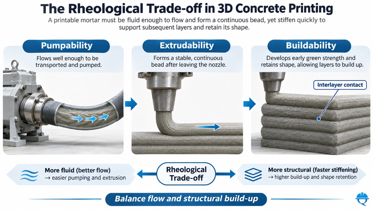
Rheology describes how a material flows or deforms under applied stress. Printable cementitious materials are time-dependent, evolving systems: the mixture is sheared in the mixer and pumping circuit, deposited at the nozzle, then left to support additional layers. Laboratory rheology and full-scale process behavior should be considered together.
- Dynamic yield stress: a measure associated with maintaining flow once the material is being sheared. High flow resistance can affect pumping and nozzle discharge.
- Static yield stress: resistance to the onset of flow after the material rests. Its evolution is important for the deposited bead's early stability.
- Plastic viscosity: resistance during continued flow; it influences energy and pressure requirements and extrusion behavior.
- Thixotropic structural build-up: time-dependent recovery of structure at rest after shear, often partly reversible. Chemical hydration and irreversible stiffening also evolve and must not be conflated with reversible thixotropy.
- Open time: the duration over which the system meets the defined production requirements. It is not necessarily equal to initial setting time.
Different rheometers, test protocols, rest periods and shear histories can produce non-identical results. A recorded number must be paired with its method, time since mixing and temperature. Treat literature values as research context unless the project has adopted and qualified the same procedure.
The flow-to-buildability trade-off
More fluid material can be easier to pump yet more likely to spread after extrusion. Faster structural build-up can preserve bead dimensions yet hinder later pumping or reduce contact with the next layer. The objective is a qualified operating window, not maximizing a single property.
Mix design and printer configuration must be developed together
Printability is not an intrinsic mix label that remains valid regardless of equipment. The same formulation may behave differently with a longer hose, narrower nozzle, a different pump, higher travel speed or different layer timing. The qualified mix-design record should therefore identify the operating system:
- Delivery system: pump type, line and hose configuration, expected pressure and practical flow range.
- Extrusion system: nozzle shape and opening, deposition orientation, nozzle standoff and any shaping device.
- Motion control: print-path revision, travel speed, acceleration, corners, start/stop behavior and target material output.
- Build sequence: intended bead width, layer height, wall geometry, printed height and time between passes.
- Production conditions: mixing sequence, holding and re-mixing practice, batch age, ambient temperature, wind, humidity and curing/protection.
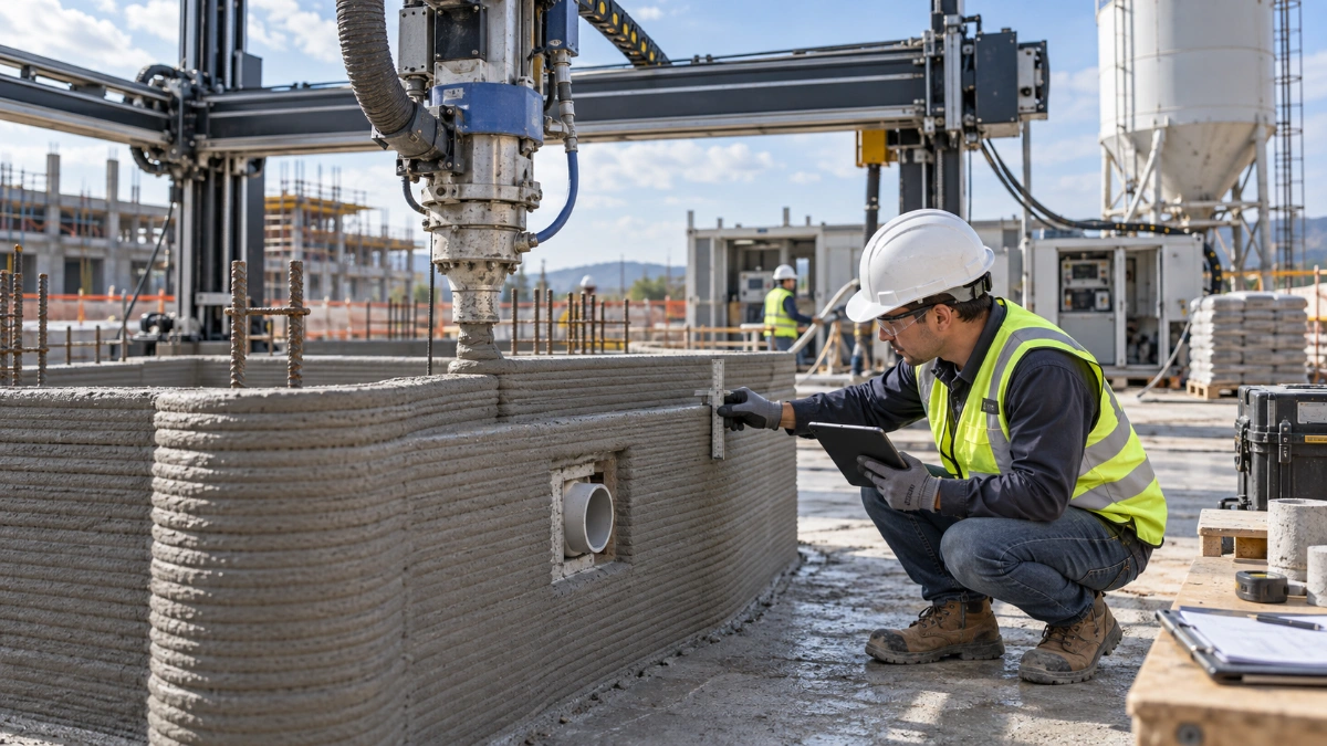
Where reinforcement, sleeves, openings or grouted cavities are involved, the qualified printing geometry and detailing must also accommodate those elements. Printed material stability is only one aspect of a complete wall system.
How to develop and qualify a 3D printable mix
The following is a practical workflow outline, not a universal specification. Each project still needs its approved qualification programme and acceptance requirements.
- Define the performance target. Identify intended structural use, exposure, required hardened properties, wall geometry, printer, material supply, print sequence, project specification and applicable approvals.
- Screen materials and calculate trial proportions. Establish documented candidate mixes, approved material sources, water/binder basis, admixture dosages, mixing sequence and moisture corrections. Check compatibility rather than merely choosing higher binder contents.
- Run controlled fresh-state screening. Record test procedure, fluidity/flow response where meaningful, material age, temperature, segregation, static/dynamic rheology and retention over the intended production period.
- Test pumping and extrusion with representative equipment. Observe continuous discharge, pressure behavior, nozzle blockage, shape consistency, bead width and edge integrity. Include realistic starts, stops, corners and flow changes.
- Conduct a buildability trial. Print representative wall geometry and record layer deformation, settlement, leaning, collapse or other instability as layers accumulate. Compare the observations with explicitly defined project criteria.
- Check time between layers and interruptions. Verify the qualified working window and any interlayer performance requirements. Assess what happens near the maximum permitted interval and after planned or unplanned pauses.
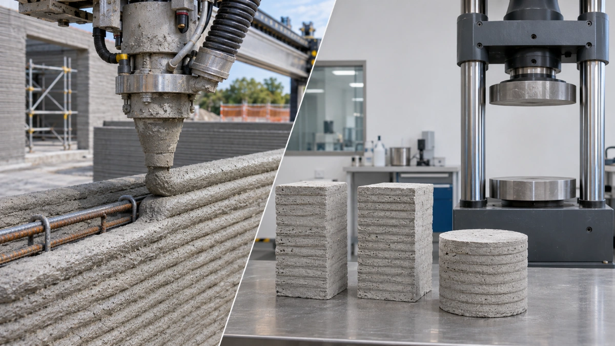
- Test hardened specimens and system performance. Use representative specimens, directions and procedures for compressive, tensile, flexural, interlayer, durability or other specified properties. The printed wall may require evidence beyond conventional cast specimens.
- Approve the operating window and production controls. Identify the qualified mix revision, permitted material substitutions, environmental/temperature range, equipment configuration, process limits, inspection and test plan, and actions when deviations occur.
A project should not move from a successful laboratory flow test straight to approval for structural wall printing. The trial-print, sampling, inspection and engineering acceptance stages provide different evidence.
Trial-mix comparison: what should the engineer record?
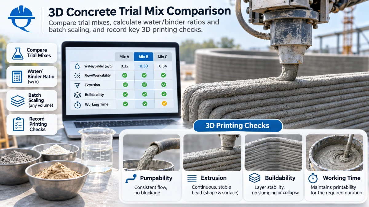
Comparing batches is more useful when each trial uses the same defined evaluation method and controls. A practical comparison should record actual measurements and observations, not award a generic “printability score” unsupported by project criteria.
Compare trial mixes with the 3D Concrete Mix & Printability Evaluator
Use the evaluator to record trial mixes, calculate water-to-binder ratios, scale batches from measured yield and estimate bead flow. Enter measured printing observations and your project criteria to compare trials and export the records as JSON or CSV.
The evaluator checks the evidence you enter against the criteria you provide. It does not predict printability from ingredients, verify interlayer strength or provide structural acceptance.
MATERIALS / TRIAL PRINTING
3D Concrete Mix & Printability Evaluator
Document a mix. Record a trial. Compare the evidence.
Compare measured trials against your own project criteria. This tool does not predict printable-mix performance or approve structural use. Blank criteria stay incomplete.
Trial identity
Batch ingredients
Enter kg for this batch. Binder includes cement and SCMs. Water must be effective free water after moisture/absorption correction, including any admixture carrier water; avoid counting it twice. Admixture mass is as-supplied product mass.
| Material | Category | Mass (kg) | Remove |
|---|
Process & batch scaling
Scaling uses measured batch yield, not assumed density. The flow estimate assumes a solid rectangular bead; actual shape, cavities, slip and delivery losses can change demand. It is a planning calculation, not a pumping acceptance limit.
Evidence against entered criteria
Use a consistent test method across trials. For qualitative checks, describe the expected condition and record your assessment. For numeric checks, enter the measured value and the project minimum or maximum. Leave an unperformed check blank.
Compare trials
Compare only trials with compatible materials, equipment, layer timing, test methods and criteria. A green trial result is a match to entered criteria, not mix approval or wall acceptance.
Keep your trial records
Work stays in this page until you export it or explicitly save it in this browser. A local save may be unavailable in private browsing or embedded views. JSON retains editable records; CSV is a flat report.
Calculation basis & limitations
Water/binder = effective free water mass ÷ total binder mass. Aggregate/binder = entered aggregate mass ÷ binder mass. Admixture dosage = as-supplied admixture mass ÷ binder mass × 100. Target quantities = batch ingredient masses × target volume ÷ measured batch yield.
Rectangular-bead demand (L/min) = bead width (mm) × layer height (mm) × print speed (mm/s) × 60 ÷ 1,000,000. This geometric estimate does not model pressure, rheology, buildability, open time, bond strength or hardened structural performance.
Qualify the material and printing system through the approved trial and testing programme. This record does not replace laboratory reports, design checks, system qualification or the project ITP. No universal acceptance limits or strength forecasts are supplied.
Open the 3D Concrete Mix & Printability Evaluator in its own page →
| Record group | Fields to capture | Why it matters |
|---|---|---|
| Mix identity | Trial ID, mix revision, materials, supplier/batch lots, water/binder, admixtures, aggregate moisture | Ensures two trials are actually comparable. |
| Mixing and age | Batch size, mix order, time stamps, temperature, rest/recirculation history | Identifies time-dependent behavior. |
| Printer configuration | Pump/hose, nozzle geometry, print speed, material output, planned layer interval | Makes trial findings transferable to the production setup. |
| Fresh-state tests | Named method, age, temperature and measured flow/rheology results | Prevents comparisons between unlike procedures. |
| Printability results | Pressure, continuity, bead dimensions, stable layers/height, deformation, stops | Connects laboratory data with actual print performance. |
| Interface and hardened tests | Sampling basis, layer direction, specimen IDs, curing, results, failure modes | Connects fresh printability to final material performance. |
| Disposition | Criterion reference, pass/fail/not tested, restrictions, reviewer, next action | Shows what was qualified and what remains unresolved. |
Useful distinction: “Not tested,” “outside the project criterion,” and “invalid test” are different statuses. None should be silently converted into an acceptance. A trial mix may be suitable for a research demonstration yet still lack the evidence needed for a particular building project.
Common 3D-printing mix problems and what to investigate
| Observed problem | Possible contributors to investigate | Recommended next check |
|---|---|---|
| Pump pressure rises or hose blocks | Mixture aging, aggregate gradation, blockage, line geometry, excessive flow resistance | Stop safely, assess the delivery system and fresh-material history against the qualified procedure. |
| Bead tears, becomes intermittent or loses shape | Discharge mismatch, nozzle constraints, material cohesion, flow variability, speed | Compare output, travel speed and bead measurements with the qualified print settings. |
| Layers spread or wall leans | Insufficient early build-up, excessive deposition rate, geometry, temperature | Check stability and trial-print limits; do not print through instability. |
| Poor contact at a new layer or restart | Extended layer interval, drying, contamination, surface stiffening or deposition changes | Record interval and process state; obtain engineering review of the interface. |
| Unexpected cracks or shrinkage | Mix volume changes, curing conditions, restraint, thermal effects, geometry | Investigate timing, exposure, curing, crack pattern and the specified system performance. |
These are investigation prompts, not automatic diagnoses. Do not adjust water or admixture dosage during structural printing without an approved change and requalification where required. A modification that improves extrusion may alter layer stability, structural performance or durability.
When a printed wall exhibits visible defects, see 3D Printed Concrete Defects — Visual Field Guide for Site Engineers. The guide addresses field recognition, recording and escalation, which are distinct from material mix design.
What does the project need to approve a printable mix?
Approval should identify the mix-plus-process combination, not merely a list of cement and sand quantities. Depending on the project and governing requirements, the package may include:
- Material specifications, certificates, sources and controlled mix revision;
- Defined printer, pump, hose, nozzle, deposition parameters and print sequence;
- Trial-batch data and valid fresh-state test procedures, times and results;
- Trial-print records demonstrating the defined pumpability, extrusion and buildability requirements;
- Qualified working window, layer intervals, restart conditions and environmental controls;
- Hardened-material testing, interlayer properties, durability and wall-system qualification appropriate to the intended use;
- Inspection and test plan (ITP) with hold/witness/review points, frequencies, evidence and authorized release;
- Rules for material substitutions, deviations, corrective actions and subsequent requalification.
3D Printed Concrete QA/QC: Inspection, Process Control & Acceptance explains the overall project quality framework. The companion 3D Printed Concrete Inspection Checklist provides five focused QChecklists for pre-print readiness, live printing, completed walls, reinforcement/embeds and interruption/restart visits.
How do current standards fit?
ICC 1150-2026 provides minimum requirements for the materials, qualification, testing, inspection and structural design of 3D concrete wall systems within its stated scope. Its relevance depends on the adopted requirements and project jurisdiction. The full standard and the approved design, rather than a summary article, govern any specific requirement.
ISO/ASTM 52939:2023 provides process-oriented quality-assurance principles for additive construction. The ISO scope explicitly excludes design approval and material-property characterization and testing. It should not be described as a complete printable-concrete mix-design or mechanical-test specification.
Research articles can help select informative trial methods, but their laboratory thresholds are not universal acceptance values for other equipment, binder systems or climates. The responsible designer and authority must determine which evidence is required for the actual printed wall.
Useful Quollnet tools for materials and production records
The 3D Concrete Mix & Printability Evaluator above supports printer-specific trial comparisons against entered project criteria. The following QMix tools support conventional proportioning and production records. These tools do not automatically qualify a printable mix or approve a printed wall.
QMix Designer — preliminary mix calculations
Explore material quantities, batch size, water–cement ratio, aggregate moisture and conventional mix-design constraints before printer-specific trials.
QMix Auditor — batch and moisture verification
Check constituent quantities and effective water-to-cementitious ratio. Conventional strength projections are not validated predictions of printed-wall properties.
QMix Logbook — materials and QA/QC recordkeeping
Record batches and conventional concrete test results. A 3D-printing trial record also needs printer settings, process time, specimen orientation, layer intervals and project-specific test criteria.
A printer-specific trial evaluation is best recorded using a system-qualified procedure that compares material and process results against entered project criteria. It must not claim to predict buildability or interlayer strength purely from the ingredient list.
How mix design connects to the rest of the 3D concrete printing cluster
How 3D Printed Houses Are Built — construction sequence and real project interfaces.
3D Printed Concrete QA/QC — qualifications, controls and acceptance records.
3D Printed Concrete Defects — field signs of potential process or material failures.
3D Printed Concrete Inspection Checklist — visit-specific checks and evidence for before, during and after printing.
Bottom line: An appropriate 3D-printable concrete mix is not determined by binder percentage or slump alone. It is a qualified combination of materials, rheology, print equipment, deposition controls, working time and verified hardened performance. The trial programme should make that relationship measurable and traceable.
References
Patel and Santhanam (2026) — Rheological and Fresh-State Characterization for 3D-Printable Concrete
An, Zhang and Yang (2024) — Incorporating Coarse Aggregates into 3D Concrete Printing
RILEM TC 304-ADC (2025) — Mechanical Properties of 3D Printed Concrete: Interlaboratory Study
ICC 1150-2026 — Standard for 3D Automated Construction Technology for 3D Concrete Walls
ISO/ASTM 52939:2023 — Additive Manufacturing for Construction: Qualification Principles