3D Printed Concrete Defects: A Visual Field Guide for Site Engineers
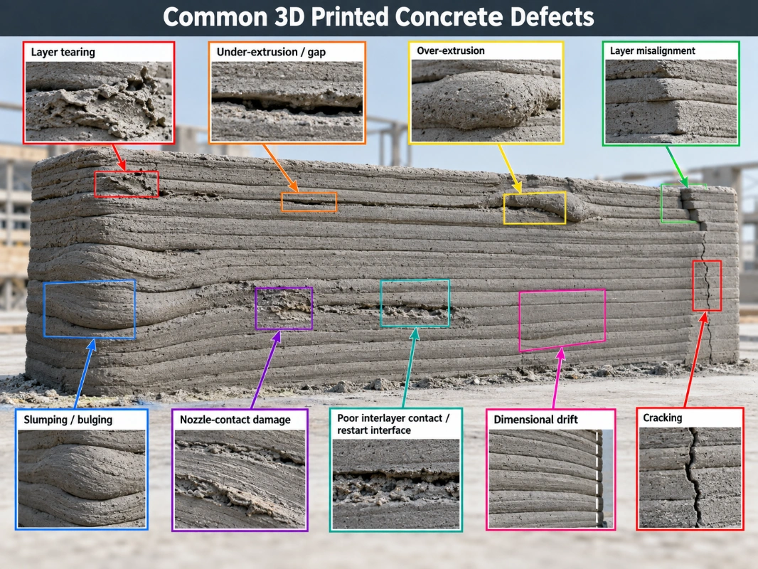
Quick Answer: Common 3D printed concrete defects include tearing, under-extrusion, over-extrusion, gaps, inconsistent bead width, layer misalignment, slumping, bulging, excessive deformation, nozzle-contact damage, weak-looking restart interfaces, cracking and dimensional drift. A visible irregularity is not automatically a structural defect, but it should be recorded when it falls outside the approved print geometry, process limits or project acceptance criteria. The field response is to document the condition, preserve its location and print history, compare it with the approved requirements, and obtain engineering review when performance may be affected.
The field question: “I am looking at the printed wall. Is what I am seeing normal?”
The answer depends on the approved wall system and tolerance. This guide helps identify suspicious conditions, but visual appearance alone cannot prove structural acceptance or rejection.
Not every irregular layer is a defect
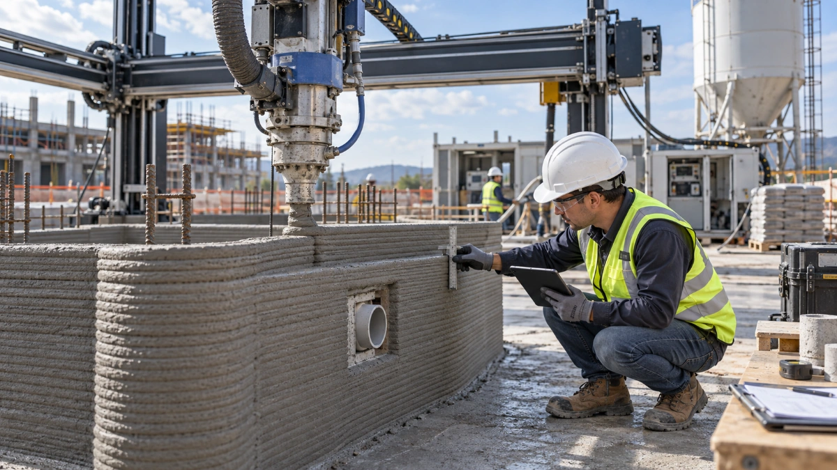
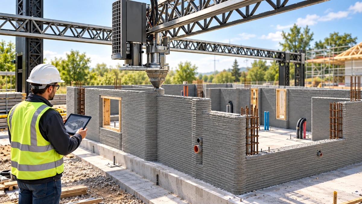
Extrusion-based 3D concrete printing intentionally leaves a layered surface. Small variations that would look unusual on a cast concrete wall may be normal characteristics of a qualified printed system. The important distinction is whether the observed condition is part of the approved geometry or whether it represents a deviation from the qualified material, print process, wall dimensions or structural requirements.
That is why defects should not be judged only by appearance. The same visible mark can have different significance depending on layer timing, wall function, reinforcement, location, exposure and whether the affected interface is part of the structural load path.
For the overall control framework, see Quollnet’s 3D printed concrete QA/QC guide. For the broader construction sequence, see how 3D printed houses are actually built.
A practical way to classify what you see
| Field condition | Typical implication |
|---|---|
| Appearance irregularity | May be cosmetic or inherent to the qualified printed finish; compare with approved samples and tolerances. |
| Process deviation | Indicates extrusion, geometry, layer timing, machine position or material behavior moved away from the approved process. |
| Nonconformance | A defined requirement, tolerance or acceptance criterion has not been met. |
| Potential structural/durability concern | Condition may affect load transfer, interlayer bonding, reinforcement, weather resistance, geometry or long-term performance and needs technical review. |
Do not repair first and document later. Record the original condition, location, affected layer or elevation, photos and relevant print history before the evidence is altered.
How to use the escalation thresholds in this guide
There is no single universal layer-offset percentage, bead-width deviation or millimetre tolerance that applies to every 3D printed wall system. ICC 1150-2026 requires the printed work to conform to the approved construction documents and qualified wall system, and it requires visible conditions such as tears, under-extrusion, bead misalignment and out-of-plumbness to be documented and reported during inspection. NIST print-fidelity research provides measurement methods rather than one universal pass/fail number.
For field screening, compare the observed condition with the approved bead width and height, wall thickness, shell/cavity geometry, line/level/plumb tolerances, qualified mock-up and permitted interruption/restart procedure. Escalate earlier when a deviation is progressive over successive layers, reduces intended contact, creates a through-depth gap, interferes with reinforcement/embeds, or affects a structural connection. Any numeric threshold used for acceptance should come from the project documents, qualified process or system supplier—not from a generic rule of thumb.
Extrusion & Bead Geometry
These defects originate mainly in material delivery, extrusion stability and the geometry of the deposited bead.
1. Layer tearing
What it looks like: The extruded bead develops rough splits, dragged edges, open surface tears or local cracking during or immediately after deposition.
Likely causes: Material may have become too stiff for stable extrusion, the printing open time may be ending, nozzle geometry or speed may be unsuitable, flow may be inconsistent, or the path may create excessive stretching at curves. Ambient drying can accelerate the problem: high wind, direct solar radiation, elevated temperature or low relative humidity can promote surface skinning and premature stiffening before or during deposition.
Why it matters: Tearing can indicate poor extrusion quality and may reduce the effective contact area between adjacent material. At corners or highly curved paths, tearing can also create local geometry and surface-quality problems.
What to record: Wall ID, layer/elevation, length of affected bead, location relative to corners/openings, material batch, print time, nozzle speed and any operator adjustment.
When to escalate: Hold or engineering review is appropriate when tearing is continuous, penetrates a significant part of the bead, occurs repeatedly, affects a structural zone or exceeds the approved acceptance criteria.
2. Under-extrusion or thin beads
What it looks like: A bead becomes narrower, lower or locally incomplete compared with adjacent printed material. The nozzle path may be correct while insufficient material is deposited.
Likely causes: Low material flow, pump inconsistency, blockage, material stiffening, incorrect flow-to-speed ratio, air or discontinuity in the delivery system, or machine-control issues.
Why it matters: Persistent under-extrusion can reduce wall thickness, contact area and dimensional conformity. It can also create gaps between beads or leave reinforcement and cavities different from the approved geometry.
What to record: Bead dimensions where measurable, length of the affected run, wall thickness, material flow or machine data if available, time and batch.
When to escalate: Compare the measured bead width/height and resulting wall thickness with the approved bead geometry and wall tolerance. Escalate when the thin bead persists or repeats, reduces intended interbead/interlayer contact, exposes reinforcement, creates a gap, changes shell/cavity dimensions or causes the wall section to move outside the approved geometry. Do not apply an arbitrary percentage reduction unless the project or qualified system defines one.
3. Over-extrusion or oversized beads
What it looks like: The bead is wider or thicker than intended, spreads laterally, crowds adjacent cavities or produces a local ridge.
Likely causes: Excessive material flow, low print speed, material that is too fluid, nozzle height problems or mismatch between commanded movement and delivered volume.
Why it matters: Over-extrusion can shift wall geometry, close designed cavities, interfere with reinforcement or embedded items, and contribute to local bulging or cumulative dimensional drift.
What to record: Bead width/height, wall thickness, cavity dimension if accessible, affected distance and whether reinforcement or inserts are obstructed.
When to escalate: Compare the oversized bead and resulting wall/cavity dimensions with the approved geometry. Escalate when excess material closes a designed cavity, interferes with reinforcement or embeds, shifts an opening/connection zone, or produces a progressive wall-thickness deviation. Acceptance should follow the project tolerance and qualified wall system rather than a generic percentage rule.
4. Discontinuous extrusion and gaps
What it looks like: The bead stops unexpectedly, contains missing segments, breaks into separate deposits or leaves visible gaps between adjacent sections.
Likely causes: Pump interruption, hose blockage, nozzle obstruction, material segregation or stiffening, loss of feed, machine pause or control fault.
Why it matters: A discontinuity can interrupt the intended wall shell or interbead contact. Its significance depends on the wall configuration, whether the gap is later filled, and whether it lies in a structural or weather-exposed zone.
What to record: Exact location, gap length and depth, layer number/elevation, duration of the interruption and the restart procedure used.
When to escalate: Escalate when the gap is through-depth, repeated, interrupts the intended wall shell, reduces the designed contact area, creates a potential water/air path, affects reinforcement or lies in a structural/connection zone. Measure the gap and compare it with the approved wall geometry; there is no universal generic gap allowance that should be assumed acceptable.
5. Inconsistent bead width
What it looks like: Bead width varies along the same print path or between successive layers without an intentional geometric reason.
Likely causes: Unstable flow, speed variation, pressure fluctuation, nozzle distance changes, material rheology changes or cornering effects.
Why it matters: Variable bead width can be an early sign that the process is losing stability. It may also lead to uneven wall thickness, misalignment or poor local contact.
What to record: A sequence of bead measurements, not only the worst point, plus the related printer speed, time and location.
When to escalate: Escalate when a sequence of measurements shows a continuing trend rather than an isolated fluctuation, when bead width moves outside the approved range, or when the variation begins to change wall thickness, cavity geometry or layer contact. Use the qualified bead dimensions and project tolerance as the acceptance reference.
Wall Geometry & Buildability
These conditions affect the overall shape, stability or position of the printed wall. The key field question is whether the deviation is isolated and stable or is progressively increasing as more layers are added.
6. Layer misalignment
What it looks like: Successive layers are laterally offset, producing a stepped edge, shifted wall face or inconsistent vertical alignment.
Likely causes: Printer coordinate error, nozzle-position error, cumulative deformation of lower layers, path-control problems, unexpected movement of the printer or substrate, or incorrect digital geometry.
Why it matters: Misalignment can reduce effective contact between layers, alter wall thickness and accumulate into an out-of-plumb wall.
What to record: Offset magnitude, direction, layer/elevation, wall face and whether the offset is isolated or continues upward.
When to escalate: Measure the lateral offset and check whether it is isolated or accumulating over successive layers. Escalate when the offset is progressive, reduces the intended contact/bearing width, changes the shell or cavity arrangement, or drives the wall outside the approved line/plumb envelope. Do not assume a generic percentage of bead width is acceptable unless the qualified wall system or project documents explicitly define it.
7. Slumping or bulging
What it looks like: Fresh layers spread sideways, sag, flatten or create a visible bulge as the wall gains height.
Likely causes: Insufficient buildability, material that is too fluid, excessive layer rate, inadequate structural build-up between layers, high temperature effects on the selected material system, or too much load from successive layers.
Why it matters: Slumping changes wall geometry while the work is still fresh. If it continues, the wall can move rapidly from a local dimensional issue to partial instability.
What to record: Wall height when deformation began, rate of progression, bead dimensions, ambient conditions, print rate and whether deformation stops when printing pauses.
When to escalate: Progressive bulging is a strong reason to hold the print. Continuing to add layers can increase deformation and make recovery difficult.
8. Progressive buildability failure
What it looks like: Lower layers compress or distort progressively as more layers are added. The wall may lean, spread, buckle or lose its intended cross-section.
Likely causes: The deposited material has not developed enough early resistance for the applied construction rate, or the selected print parameters exceed the stable process window.
Why it matters: This is not only a surface defect. Buildability is the ability of the fresh printed element to support the growing self-weight of the wall. Progressive deformation can culminate in instability or collapse.
What to record: Height, layer count, deformation versus time, print rate, material age and the point at which the trend began.
When to escalate: Stop and obtain technical review when deformation is increasing rather than stabilizing, especially on tall, slender or load-bearing printed elements.
9. Local buckling or collapse
What it looks like: A section of the fresh wall folds, leans sharply, ruptures or collapses under its own weight.
Likely causes: Severe loss of buildability, excessive height/rate, geometric instability, weak local layers, collision or a combination of material and process problems.
Why it matters: Collapse is a clear loss of geometry and process stability. It can also create an immediate site-safety hazard around moving equipment and unsupported fresh material.
What to record: Preserve the print log, material batch, wall geometry, layer timing, photos/video and machine state at the moment of failure.
When to escalate: Immediately. The affected print should not simply be trimmed and continued unless an approved technical disposition allows it.
10. Dimensional drift and out-of-plumb walls
What it looks like: The wall gradually shifts from its intended position, thickness or vertical alignment even though no single layer appears dramatically wrong.
Likely causes: Small repeated bead offsets, deformation, coordinate/calibration error, substrate movement, printer position drift or accumulated corner/path effects.
Why it matters: Small deviations can accumulate. Final wall position affects connections, roofs, openings, MEP, finishes and structural load paths.
What to record: Survey or dimensional measurements at several elevations, not only the top of the wall.
When to escalate: Escalate when the trend is progressive, when survey measurements show the wall moving away from the approved line/level/plumb envelope, or when the deviation affects a connection or interface with conventional construction. ICC 1150-2026 does not establish one universal millimetre or percentage limit for every printed system; the governing tolerance comes from the approved construction documents and qualified wall system.
Interfaces & Process Interruptions
These conditions occur where adjacent beads or layers should act together, or where printing stops and later resumes. They deserve careful traceability because visual appearance alone cannot establish interlayer performance.
11. Voids, cavities or incomplete bead contact
What it looks like: Visible pockets, open spaces or incomplete contact where adjacent beads or layers should meet according to the approved wall configuration.
Likely causes: Under-extrusion, bead misalignment, surface drying, irregular deposition, trapped debris, geometry at corners/intersections or interruption/restart effects.
Why it matters: Interlayer and interbead interfaces are important features of printed construction. Voids can reduce effective contact area and may affect strength, permeability or durability depending on the wall system.
What to record: Location, approximate size, orientation, whether the void is at a layer interface or between adjacent beads, and whether it is open to the exterior.
When to escalate: When voids are repetitive, deep, aligned along a critical interface, expose reinforcement, create a water path or fall outside the qualified system.
12. Poor interlayer contact or suspected delamination
What it looks like: Layers appear poorly seated together, a visible separation persists along an interface, edges lift, or a later crack follows the layer boundary.
Likely causes: Long interlayer delay, drying or contamination of the previous layer, poor bead geometry, low deposition pressure/contact, material evolution or environmental exposure. High wind, direct solar radiation, elevated temperature and low relative humidity can accelerate surface drying or skin formation on the exposed layer before the next bead is deposited, increasing the risk of poor contact at the interface.
Why it matters: Research consistently identifies the layer interface as a possible plane of weakness and a source of anisotropic behavior in 3D printed concrete. Visual separation does not quantify bond strength, but it is an important condition to preserve and investigate.
What to record: Interface elevation, length, associated time gap, environmental conditions and whether the condition coincides with a planned or unplanned stop.
When to escalate: When there is actual separation, delamination, repeated interface cracking, an excessive interruption or a structural requirement tied to interlayer performance.
13. Long print interruption or restart interface
What it looks like: A distinct horizontal or inclined interface marks where printing stopped and later restarted. The restarted bead may have different texture, geometry or contact.
Likely causes: Planned pause, pump/nozzle blockage, material change, equipment fault, embed installation, weather or another site interruption.
Why it matters: A restart is not automatically defective, but longer time gaps can change moisture condition, rheology and the quality of the interface between old and new material.
What to record: Stop/restart times, layer/elevation, reason, surface condition, preparation before restart, material batch and approval to continue.
When to escalate: When the interruption exceeds the approved limit, the restart surface has dried/contaminated, the interface is visibly open, or the project requires testing or engineering disposition.
Equipment Contact, Post-Printing & Embedded Elements
This final group covers damage from printer contact, cracking that becomes visible after deposition, coordination errors involving embedded items, and later site damage.
14. Nozzle drag or nozzle-contact damage
What it looks like: The nozzle scrapes a previous layer, pushes fresh material sideways, leaves a gouge or disturbs reinforcement/embeds.
Likely causes: Incorrect nozzle height, deformation of previous layers, calibration drift, path error, obstacle interference or an embed/reinforcement position different from the digital model.
Why it matters: Contact can damage an otherwise acceptable layer and may indicate the physical wall geometry no longer matches the machine’s assumed geometry. Dragging or repeated contact can also transmit local shear, vibration or disturbance into still-fresh underlying layers, so the affected zone may extend below the visibly scraped surface and may influence interlayer contact several layers down.
What to record: Contact location, affected layers, machine/nozzle position, visible disturbance and any affected reinforcement or insert. Record whether the underlying wall was still fresh and whether movement or cracking appeared below the direct contact point.
When to escalate: Escalate when contact damages a structural section, reinforcement, opening or connection zone; when disturbance is visible below the contacted layer; or when contact recurs because the printer/wall coordinate relationship has drifted.
15. Cracking after printing
What it looks like: Cracks may run through a bead, follow a layer interface, occur at corners/openings, or develop during drying and curing.
Likely causes: Plastic or drying shrinkage, thermal/moisture effects, restraint, weak interlayer contact, geometric stress concentration, settlement/deformation, loading or impact.
Why it matters: Crack orientation and timing matter. A fine surface crack is different from a crack that follows a long structural interface or passes through a connection zone.
What to record: Crack location, length, width where practical, orientation, date/time first observed, whether it is growing and its relationship to layers, openings and restart interfaces.
When to escalate: Structural review is appropriate for widening cracks, repeated interlayer cracks, through-thickness cracks, cracks at structural connections, or cracks outside the project’s acceptance criteria.
16. Misplaced opening, sleeve, embed or reinforcement
What it looks like: A door/window opening, sleeve, electrical box, insert, anchor or reinforcement is missing, shifted or conflicts with the printed material.
Likely causes: Wrong model/print revision, coordination error, missed installation window, inaccurate setting-out or print-path mismatch.
Why it matters: Cutting or drilling a printed structural wall after the event may interrupt reinforcement, cavities, weather layers or load paths. The defect is therefore not simply dimensional.
What to record: Approved intended position, actual position, wall layer/elevation, reinforcement/cavity arrangement and whether printing has passed the point where correction was planned.
When to escalate: Before cutting, chasing or drilling. Obtain the required technical disposition where structural, waterproofing, fire or reinforcement implications exist.
17. Surface damage after printing
What it looks like: Chipping, impact damage, abrasion, gouges or broken edges after the material has been deposited.
Likely causes: Site traffic, equipment contact, premature handling, scaffold/temporary-work contact, later trades or inadequate protection.
Why it matters: Some damage is cosmetic; other damage removes part of the intended wall section or exposes reinforcement/cavities.
What to record: Dimensions, depth, location, cause if known and whether the damaged area is structural or weather-exposed.
When to escalate: Where damage changes the effective section, exposes reinforcement, affects a connection or requires a repair not already covered by an approved method.
Which conditions usually deserve immediate attention?
Project-specific requirements govern the decision, but the following conditions generally deserve a prompt hold or technical review rather than “print now, inspect later”:
- progressive slumping, bulging, buckling or instability;
- local collapse;
- repeated extrusion discontinuity or major gaps;
- significant layer separation or delamination;
- rapidly increasing dimensional drift;
- nozzle collision that affects reinforcement, embeds or a structural section;
- an interruption outside the approved restart procedure;
- missing or displaced structural reinforcement/connection items;
- cracking that is widening, through-thickness or concentrated at critical interfaces; and
- any condition outside a defined structural, geometric or process acceptance limit.
What should a field defect record contain?
A photograph alone is usually insufficient. The value of the record comes from linking what is visible to the print history.
- project and wall/print-segment ID;
- date and time;
- layer number or elevation;
- drawing/model and print-file revision;
- material/mix batch;
- printer/nozzle identification where relevant;
- photos with scale and wider context;
- measured dimensions or crack/void size where practical;
- environmental conditions;
- stop/restart times if an interruption is involved;
- related reinforcement, embed or opening;
- applicable acceptance criterion or tolerance;
- temporary hold/protection action; and
- technical disposition, repair and close-out evidence.
Where the condition is being presented for inspection, the project can use its normal Work Inspection Request (WIR) workflow with the print-specific evidence attached. If the condition is confirmed to breach a requirement, Quollnet’s Observation vs NCR vs Snag vs Defect guide helps distinguish the appropriate record, and the NCR guide explains the non-conformance process.
Defect inspection should be tied to the ITP
The defect guide is most useful when the project has already defined what is acceptable. A project-specific Inspection & Test Plan (ITP) can identify the stages at which bead geometry, wall geometry, reinforcement, materials and completed printed work are checked and recorded.
ICC 1150-2026 establishes a current code-oriented framework for material qualification, inspection, interlayer/interbead performance and construction quality assurance for 3D printed wall systems. The specific field tolerances still need to come from the applicable construction documents, qualified wall system and project requirements.
Visual inspection cannot answer every question
A visually smooth interface may still have weak bond, while a visible surface irregularity may be acceptable within a qualified wall system. NIST notes that the layered process creates anisotropy and that conventional hardened-material or structural test methods may not always transfer directly to 3D printed construction.
That is why this article stops at recognition and field response. The separate Quollnet article How Is 3D Printed Concrete Tested? will cover printed specimens, companion walls, directional testing, interlayer performance and acceptance evidence in detail.
Field rule: identify the condition → preserve the evidence → compare with the approved requirement → hold when continued printing could conceal or worsen the issue → obtain the required technical disposition → verify the repair or acceptance decision.
References
ICC 1150-2026 — Standard for Automated Construction Technology for 3D Printing Walls
NIST — Additive Manufacturing with Cement-based Materials
NIST — Print Fidelity Metrics for Additive Manufacturing of Cement-based Materials
NIST — Additive Construction in Practice: Realities of Acceptance Criteria
NIST — Assuring the Long-Term Performance of Additively Constructed Structures