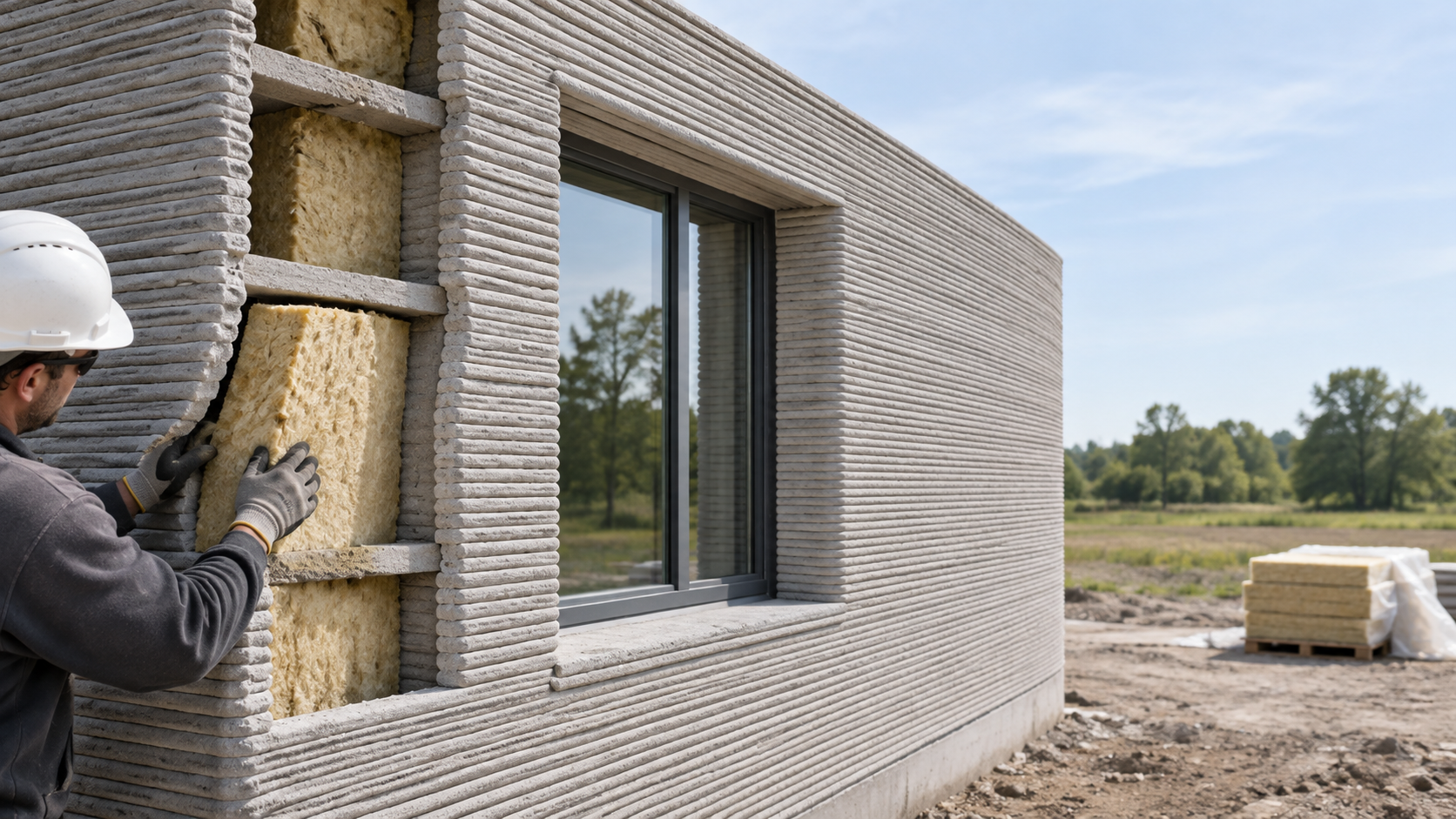
How Are 3D Printed Houses Insulated? What the Wall Section Must Get Right
Quick Answer: 3D printed houses are insulated by designing a complete wall assembly around the printed concrete, not by assuming that printed layers or hollow cavities provide adequate insulation on their own. Common approaches include insulating wall cavities, adding continuous exterior or interior insulation, or combining both. The effective thermal performance depends on concrete webs and other thermal bridges, the continuity of air and water barriers, moisture control, junction details, and the requirements of the local energy code.
The key design distinction: A printed-concrete wall can be structurally sound and visually impressive yet perform poorly as a building envelope. Before calling a printed home “energy efficient,” verify the complete wall section—including insulation, concrete webs, junctions, openings, air leakage and moisture—not just the printed material or the size of its cavities.
Do 3D printed concrete walls need additional insulation?
Usually yes, where the printed wall forms part of the conditioned building envelope. Cementitious materials provide thermal mass, but ordinary printed concrete is not automatically a high-resistance insulation material. Some engineered printable mixes have different conductivity from conventional concrete; that alone does not establish an acceptable building-envelope performance. The correct solution depends on the wall topology, materials, local climate, energy requirements and the structural design.
Extrusion-based 3D concrete printing may create solid walls, two printed skins separated by cavities, webs connecting those skins, or more complex lattice shapes. The voids can accommodate insulation, but concrete ribs and connections can conduct heat across the wall. A large empty air cavity is also not necessarily an effective insulator: air movement within it can increase heat transfer.
Recent experimental and modeling research shows that internal geometry, cavity infill, continuous insulation and moisture conditions strongly influence thermal performance. For construction context beyond the wall envelope, see How 3D Printed Houses Are Built: What the Viral Videos Don’t Show You.
Understand thermal mass, R-value and U-value before comparing walls
- Thermal conductivity (λ): how readily a material conducts heat, usually expressed in W/(m·K). Lower conductivity generally means better material-level insulation.
- Thermal resistance (R-value): resistance to heat flow, expressed in m²·K/W in SI units. A higher R-value is better for a comparable assembly.
- Thermal transmittance (U-value): heat flow through an assembly per unit area and temperature difference, expressed in W/(m²·K). A lower U-value generally indicates less heat transfer through the assembly.
- Thermal mass: the ability to store and release heat over time. It can moderate temperature swings under suitable conditions, but it is not a substitute for adequate insulation or airtightness.
- Thermal bridge: a more conductive path that bypasses insulation, such as a concrete web, reinforced junction, slab edge, anchor or window reveal.
For a homogeneous layer, a useful preliminary relation is R = thickness (m) ÷ design thermal conductivity (W/(m·K)). For example, a hypothetical 0.10 m insulation layer with design conductivity 0.040 W/(m·K) has a nominal material-layer resistance of 2.5 m²·K/W. That is not the U-value or verified R-value of a complete printed wall: supports, junctions, surface resistances, cavities, installation defects and moisture may change the result.
ISO 6946:2017 sets out calculation methods for building elements within its scope; printed walls with substantial 2D or 3D heat-flow paths may require detailed thermal-bridge modeling rather than a simple stack-of-layers calculation. ISO 10211:2017 addresses detailed calculation of heat flows and surface temperatures around bridges. Always use appropriate design conductivities and the procedure accepted in the project jurisdiction.
Four common insulation arrangements for 3D printed walls
These are conceptual arrangements, not interchangeable standard details. Fire protection, strength, cavities, fixing systems, cladding, moisture control and energy compliance must be designed for the particular building.
| Wall arrangement | Potential advantage | Main design check |
|---|---|---|
| Solid printed concrete plus continuous insulation | Relatively straightforward insulation continuity where geometry allows. | Substrate, fixings, moisture, fire detailing and interfaces with windows/roof/foundation. |
| Two printed skins with air cavities and connecting webs | Material-efficient wall geometry and potential space for later services or insulation. | Concrete-web heat paths, natural convection in large cavities, moisture pathways and air leakage. |
| Cavity-filled insulation between printed skins | Improves use of existing wall voids without always adding outer thickness. | Complete filling, void geometry, web bridging, compatibility, water management and access for inspection. |
| Cavity insulation plus continuous exterior/interior insulation | Can reduce bypass through printed webs and improve envelope continuity. | Location-specific condensation, vapor control, attachment, fire and durability strategy. |
A 2026 review of 3D-printed wall building science found that modifying the concrete mix, print geometry or cavity infill alone is unlikely to satisfy thermal requirements across all climate zones. Continuous insulation is an important option, but its location and moisture implications need engineering review rather than an automatic rule. It is therefore misleading to claim that all 3D printed houses use the same insulated hollow wall.
Why can hollow printed walls still lose heat?
Many printed cavity walls contain ribs or webs connecting the exterior and interior skins. These connections are required for the system's geometry or load path, but they may create conductive bridges through the insulation zone. Corners, jambs, headers, slab supports and reinforcement add further paths.
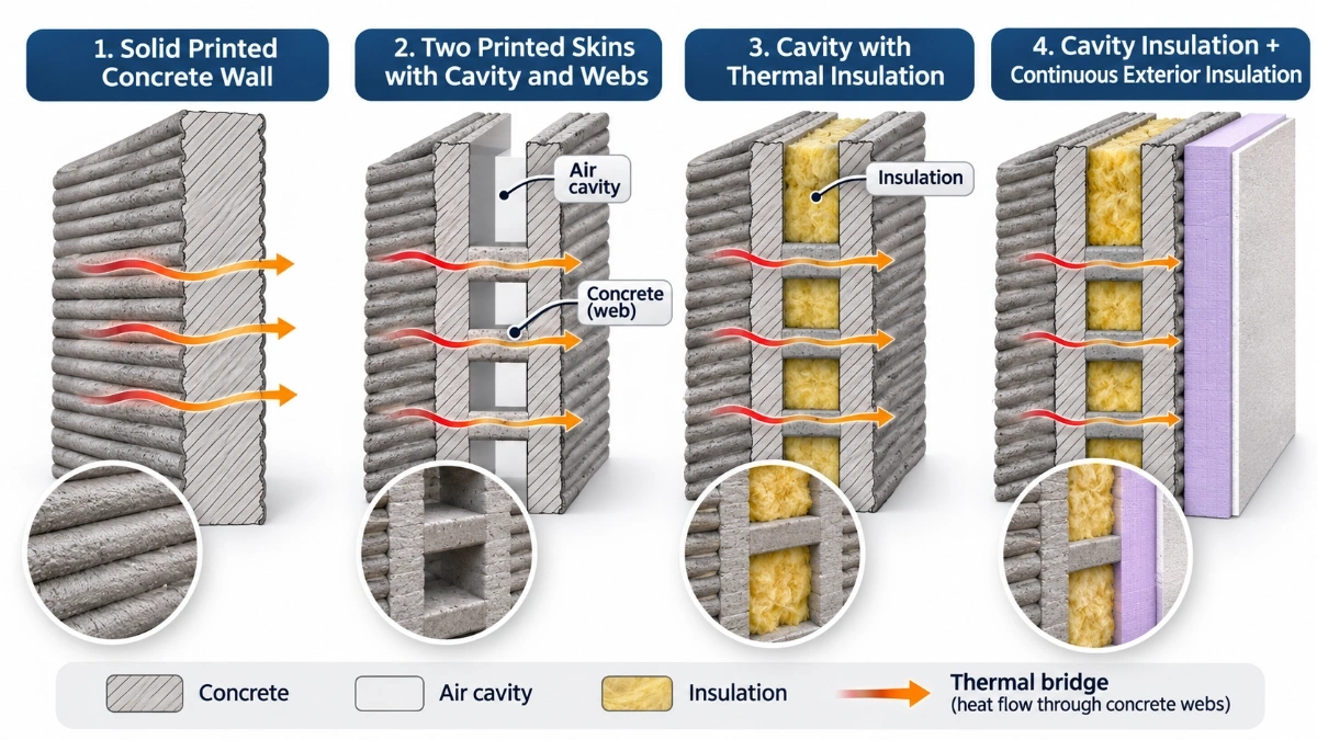
Research on printed lattice geometries found that wall thermal behavior changes with web length, filament width and contact between internal webs and outer skins. Filling the cavities may improve resistance, but it does not remove the concrete bridges. Other studies of relatively large air cavities found that buoyancy-driven convection can reduce the benefit of an unfilled cavity. Air space is not equivalent to certified insulation.
How should concrete webs and thermal bridges be assessed?
- Obtain the actual printed section, not merely an architectural wall thickness.
- Identify every solid connection, reinforcement element and anchor through the insulation zone.
- Use tested or justified thermal conductivities for materials in their relevant condition.
- Calculate thermal transmittance using a suitable method and detailed heat-flow modeling where the geometry requires it.
- Include critical edge details: floor slab, foundation, roof, corners, openings and material transitions.
- Verify the effective assembly performance against the applicable project energy requirements.
A nominal cavity-fill product R-value cannot simply be assigned to the whole cross-section when the cavity is crossed by concrete webs. Designers should obtain an effective assembly U-value and address relevant linear and point thermal bridges.
Is insulation better outside, inside or in the printed cavity?
No location is universally best. The choice affects heat loss, rain exposure, drying behavior, interior area, thermal-mass exposure, cladding and inspection. It also influences whether the recognizable printed-concrete texture remains exposed.
Continuous exterior insulation
Exterior insulation may reduce thermal bridging and keep the structural concrete on the warmer side of the insulation in many heating-dominated conditions, but it needs a designed weather-control, drainage, cladding-attachment and fire strategy. Windows, parapets and roof lines must connect to the insulated and weather-managed assembly. An exposed textured printed finish may be hidden or require a suitable compatible facade system.
Continuous interior insulation
Interior insulation may preserve the exterior printed appearance and simplify some retrofit-like arrangements, but can change temperature and drying conditions inside the concrete wall. Vapor and moisture risks cannot be judged from location alone. Analyze the actual climate, rain exposure, materials, indoor humidity and air-barrier positions.
Insulation inserted into printed cavities
Potential options include suitable spray-applied, injected, panel or loose-fill systems where the cavity geometry, product approvals and project fire/moisture strategy permit. Each method needs verification that the insulation reaches all intended voids and does not obstruct drainage, services, reinforcement, grouting or other required functions. Closed or narrow compartments can be difficult to inspect after filling.
Important: Insulation is not a structural grout and should not be substituted for specified concrete infill or reinforcement. Conversely, a structural grout zone should not be counted as an insulation layer without evidence.
Air barriers, rainwater and vapor control are different jobs
Even an assembly with good calculated thermal resistance can perform poorly if uncontrolled air movement or water enters the wall. In printed construction, irregular layer surfaces, print stops, joints between segments and junctions with conventional building elements merit explicit detailing.
- Water control layer: manages liquid rainwater and directs it safely to the exterior. Consider exposed layer interfaces, coatings/claddings, drainage, flashings, cavity drainage and penetrations.
- Air barrier: limits uncontrolled air leakage through the enclosure. Identify the continuous plane and detail transitions to windows, doors, roof, slab and service penetrations.
- Vapor control: addresses moisture diffusion as necessary for the climate and assembly. A vapor retarder is not necessarily an air or rain barrier, and a fully vapor-impermeable layer is not automatically correct.
- Thermal control: supplies required insulation while minimizing bridges. Its continuity must be checked separately from the air and water barriers.
Experimental work published in 2025 investigated wind-driven rainwater penetration and thermal resistance in large-scale 3D-printed cementitious walls. This is a reminder that rain exposure and print interruptions deserve attention even when thermal calculations look satisfactory. Another experimental/numerical study reported that moisture absorption could weaken the thermal performance of a multilayer printed-wall system.
ISO 13788:2012 provides simplified methods for surface-condensation and vapor-diffusion risk assessment, but explicitly excludes several mechanisms such as liquid moisture transport, capillary suction, air movement through gaps and moisture-dependent material properties. Complex printed wall geometries may therefore require a more complete hygrothermal assessment. Do not conclude “no condensation risk” from a simple steady-state check if those excluded mechanisms are material.
Why are windows, doors, slabs and roofs critical?
A published thermal performance value for the center of a wall does not describe the whole building. Three-dimensional printed homes commonly connect to conventional foundations, reinforced structural elements, roof systems, glazing and interior services. These junctions are frequent sources of discontinuity:
- Window and door reveals: coordinate frame position, insulation return, head/sill flashings, airtight seals and drainage without trapping water.
- Foundation/base: resolve thermal continuity at slab edge and footing-to-wall connection, including damp-proof and capillary-break strategy where required.
- Roof/parapet: coordinate roof insulation and waterproofing with the printed wall, structural support and drainage.
- Concrete webs and reinforcements: assess conductive paths through cavity zones, including steel, ties and required grout regions.
- MEP sleeves and boxes: coordinate holes, services and seal systems before printing or closing cavities; protect the continuity of each control layer.
Do not cut unplanned service chases or penetrations through a printed structural wall without an approved detail. A repair material or sealant may be adequate for one function but not for the structural, air, water, thermal and fire requirements together.
The 3D Printed Concrete Inspection Checklist supports inspection around embeds, openings and concealment, while the 3D Printed Concrete QA/QC guide explains how such checks fit the project approval process.
How should thermal performance be calculated and verified?
Start with the specified energy-compliance method and climate zone for the project. A credible submittal should identify the tested or calculated properties of the actual wall system, not present the insulation product label as the whole-wall result.
| Evidence | Best use | Limitation |
|---|---|---|
| ISO 6946 calculation | Wall thermal resistance/transmittance calculation within the method's scope. | Complex geometry and substantial bridges may exceed simplified assumptions. |
| ISO 10211 numerical thermal-bridge analysis | Detailed 2D/3D heat flow and local surface-temperature assessment. | Requires correct geometry, material properties and boundary conditions. |
| ASTM C1363 hot-box assembly test | Measured steady-state performance of a representative wall assembly. | Test setup/size and conditioning matter; it does not test uncontrolled moisture or air infiltration under its normal procedure. |
| ISO 9869-1 in-situ heat-flow measurement | Field check on suitable plane opaque components. | Measurements near significant thermal bridges and inhomogeneities may not represent whole-wall performance. |
| Air/water and moisture assessment | Check enclosure continuity, leakage, durability and condensation risk. | These address different performance questions; none is replaced by a U-value. |
A final energy-compliance package may also need whole-building modeling, fenestration values, air-leakage assessment and jurisdiction-specific envelope provisions. The relevant requirements differ by location, occupancy, climate and project approval pathway. This article does not prescribe universal wall thicknesses or U-value limits.
In-situ U-value research on printed buildings has shown the risk of thermal bridging at wall joints, embedded structural members and openings, as well as benefits from insulation infill and continuous insulation in the studied assemblies. These are case-specific findings; they are not transferable design limits for every 3D printed house.
Construction inspection: what should be checked before a printed wall is closed?
An effective envelope inspection is a coordinated site visit, not merely a visual check that insulation has been placed somewhere inside the wall. The approved drawings and inspection/test plan (ITP) should define the applicable witness or hold points.
| Inspection stage | Checks | Record |
|---|---|---|
| Before insulation | Approved wall section and revisions; cavity shape/clearance; structural webs; service, anchor and drainage provisions; substrate condition. | Location-tagged drawings, measurements and photos. |
| During installation | Correct approved insulation and installation method; cavity fill or board continuity; fit around webs; fixings; no unapproved substitutions. | Material ID, installer, coverage and before-concealment photos. |
| Junction and barrier detailing | Continuous thermal, air and water-control planes at openings, roof, slabs, penetrations and terminations; planned drainage and drying paths. | Detail reference, seal materials, photographs and corrective actions. |
| Before concealment/release | Open items resolved, critical inspection points witnessed, required barrier/insulation continuity checked, authorized release obtained. | Inspection record, test references, sign-off and as-built details. |
Do not close an unverified cavity. Once later layers, infill or cladding conceal the insulation and barrier interfaces, proving full coverage or repairing a missed junction becomes harder and potentially disruptive. A proposed 3D Printed Wall Thermal & Envelope Review Checklist could formalize these visits, but no such dedicated checklist or downloadable file is supplied by this article.
Six questions before approving a printed-wall thermal design
- Which exact wall type is specified? Obtain cross-sections of the printed skins, cavities, concrete webs and structural connections.
- Where is the continuous insulation layer? Identify whether bridges across that layer are accounted for, and whether cavity-fill alone is sufficient for the approved requirement.
- What are the tested or calculated whole-wall U-value and junction losses? Confirm appropriate methods, conditions, input materials and compliance pathway.
- How will air, rainwater and vapor be controlled? Show explicit continuous planes and their details at openings, roof, slab and penetrations.
- Can the intended assembly be built and inspected? Confirm access for fill and QA/QC, insulation support and stability, fire requirements and repair feasibility.
- What changes trigger redesign or re-verification? Track print-pattern changes, infill products, cavity dimensions, window positioning and other deviations from the qualified section.
Related 3D printing guides on Quollnet
How 3D Printed Houses Are Built — the full construction sequence, not just the printer.
3D Printable Concrete Mix Design — material selection, fresh properties, printability trials and qualification; mix rheology does not replace thermal-envelope design.
3D Printed Concrete QA/QC — project quality and acceptance framework for printed walls.
How Is 3D Printed Concrete Tested? — printed specimens, interlayer behavior and hardened material verification.
3D Printed Concrete Inspection Checklist — focused field checks for preprint, active printing, reinforcement/embeds, stops and completed walls.
Bottom line: 3D printing offers opportunities to form useful cavities and optimized wall geometry, but energy efficiency is achieved by designing and verifying the entire enclosure. Combine appropriately located insulation with controlled thermal bridges, continuous air and rainwater barriers, climate-suitable moisture detailing, and evidence that the as-built wall matches the approved section.
References
Heat Transfer in a 3D-Printed Multilayer Wall System: Experimental and Numerical Analysis (2025)
Bayat and Kashani (2025) — Reducing Material and Energy Consumption through 3D-Printed Wall Designs
Thermal Performance of 3D Concrete Printed Walls: Calculated and In-Situ Measured U-Values (2023)
ISO 6946:2017 — Thermal Resistance and Thermal Transmittance: Calculation Methods
ISO 10211:2017 — Thermal Bridges in Building Construction: Detailed Calculations
ISO 13788:2012 — Internal Surface Temperature and Interstitial Condensation: Calculation Methods
ISO 9869-1:2014 — In-Situ Measurement of Thermal Resistance and Thermal Transmittance
ASTM C1363-24 — Thermal Performance of Building Materials and Envelope Assemblies by Hot Box