Reinforcement in 3D Printed Houses: What Carries the Loads and How It Is Inspected
Quick Answer: 3D printed concrete walls can be reinforced with bars in grouted cores, horizontal steel, conventional reinforced-concrete members, or qualified in-process reinforcement systems. The appropriate solution depends on whether the wall carries gravity, lateral or nonstructural loads. The critical requirement is a verified load path through reinforcement, grout or printed material, connections, floors and foundations—not simply the presence of steel inside a printed wall.
First identify the structural system. A bar visible in a hollow printed wall does not make the wall structurally adequate. The engineer must demonstrate how forces reach the steel, how steel bonds to surrounding grout or concrete, and how the entire wall connects to the foundation, floors and roof.
Do 3D printed concrete houses always need reinforcement?
Not every wall has the same structural role. A non-load-bearing partition, a printed facade, a bearing wall and a shear wall have different requirements. Some qualified printed wall systems may be permitted to perform without conventional steel reinforcement in particular applications. Many buildings instead use reinforced cores or conventional structural members integrated with the printed shells. Whether reinforcement is required, and how much, must be resolved by the project's structural engineer and the applicable approval framework.
Extrusion-based 3D concrete printing (3DCP) forms successive layers without conventional formwork. It may also form internal cavities, webs and discontinuous printed interfaces. These features can make conventional rebar placement difficult and can change how stresses transfer between layers. The designer still has to address gravity loads, bending, shear, cracking, stability and connection forces.
Our guide to how 3D printed houses are actually built covers the overall construction sequence. This article focuses on the structural details that cannot be left to the printing process alone.
Four different structural arrangements for printed concrete walls
A print file does not define a structural system by itself. The approved engineering drawings must state whether the printed concrete acts structurally, serves as permanent formwork for a cast core, or is supported by another frame.
| Arrangement | Primary intended load path | Main engineering question |
|---|---|---|
| Qualified unreinforced printed wall | Printed cementitious material and its qualified interfaces. | Are all material, layer, stability and connection capacities verified for the intended structural role? |
| Printed shell with reinforced core | Steel and grouted or cast concrete within designed cavities; any shell contribution must be justified. | Are cavities, reinforcement, anchorage, fill and shell/core interaction adequate? |
| Reinforcement incorporated during printing | A qualified composite of embedded reinforcement and deposited material. | Is bond, continuity, cover, development and directional behavior established? |
| Conventional frame with printed enclosure | Conventional reinforced concrete or another engineered structural frame. | Are wall stability, attachment, movement, loads and connections to the frame designed? |
Do not treat a printed skin as effective concrete cover, confinement or composite load-bearing concrete just because it remains in place. Those properties must be permitted by the relevant design and system qualification.
Which reinforcement methods are used in 3D concrete printing?
The literature identifies conventional and experimental approaches. The following comparison describes their basic applications rather than recommending a universal method.
| Reinforcement | How it is incorporated | What must be demonstrated |
|---|---|---|
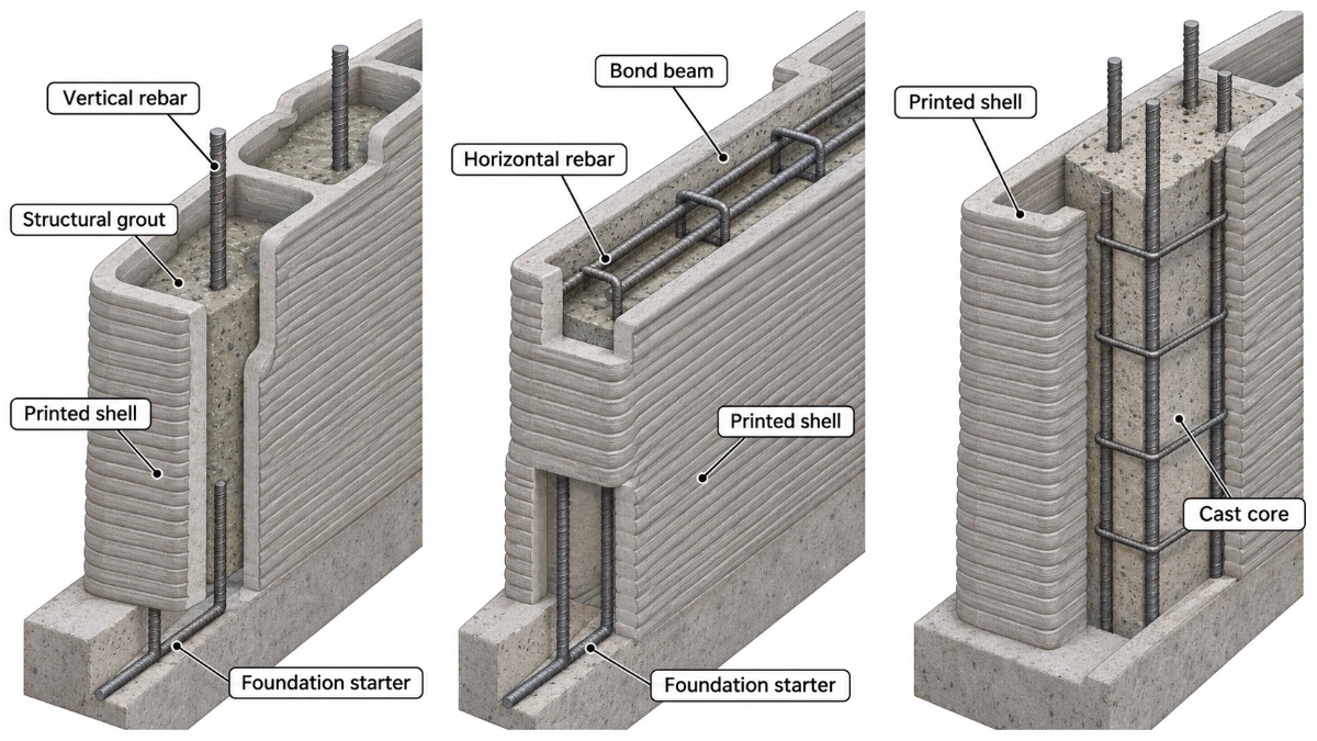
| Vertical rebars in grouted cores | Bars positioned in aligned wall cavities, tied to starter bars, then enclosed in approved grout or concrete. | Core continuity, anchorage, cover, complete filling, shell stability and load transfer. |
| Horizontal bars, meshes and trusses | Placed at designated levels or into channels as the wall is built. | Bond, cover, lap, placement tolerances, print-path clearance and continuity. |
| Bond beams, lintels and reinforced boundary elements | Cast or grouted reinforced members integrated into selected printed regions. | Gravity and lateral-force paths, bearing, connection and interface capacity. |
| Cables, wires or automated mesh | Deposited or inserted using specialized mechanisms synchronized with printing. | System-specific anchorage, repeatability, directional response and durability. |
| Discrete fibers in the printable mix | Distributed through the mixture before extrusion. | Orientation, verified residual strength, toughness and actual structural role. |
A 2025 review in Materials describes a range of reinforcement approaches, from conventional steel to cables, mesh and fibers. More recent experiments have demonstrated in-situ fabricated meshes and bidirectional steel wire. A laboratory demonstration does not mean the technique is approved for general building construction.
How are vertical bars installed in a printed concrete wall?
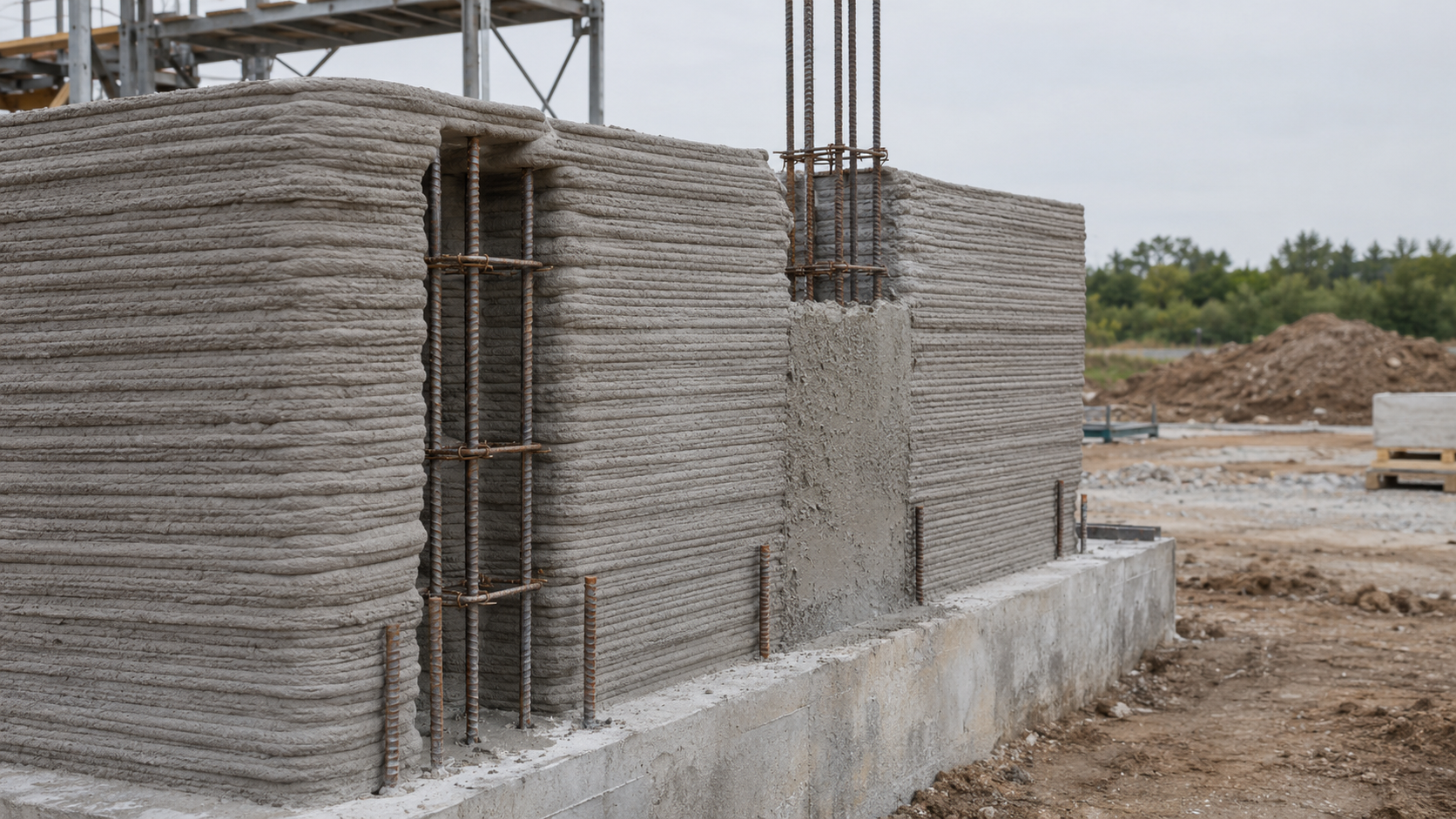
A common practical concept is to print permanent shell cavities, position or retain reinforcing steel within specified cores, and fill those cores with approved concrete or grout. The exact sequence depends on whether steel is installed before printing, during a pause or after the wall has been formed.
- Verify foundations and starter bars. Survey locations, elevations, bar sizes, positions, approved anchorage and coupler details before the print path is released.
- Verify the void geometry. Check cavity clearances, web positions and continuity against the structural section. Not every empty void in a printed wall is a grout core.
- Position and secure reinforcement. Ensure correct grade, number, orientation, specified laps, mechanical splices and spacers so steel does not drift or touch unintended surfaces.
- Inspect before filling. Review bar placement, cover, core cleanliness, access and the approved grout procedure while defects remain visible and correctable.
- Place infill using the approved sequence. Control material properties, leakage, segregation, fill continuity and fresh-material pressure on the printed skins.
- Record test and release evidence. Identify fill locations, batch references, time, observations, corrections and the inspection approvals required by the project ITP.
There is an important construction risk: an unqualified printing shell can crack, deform or separate when fresh grout imposes pressure. The design must account for temporary stability and prescribe an appropriate filling sequence and any supports. This article does not specify universal grout lift heights or waiting times.
Can a printed shell act as permanent formwork for reinforced concrete?
Yes, in a qualified printed–cast system. A printed shell can form a permanent enclosure for reinforcement and a cast or grouted core. But its structural function may differ from conventional formwork: the engineer must specify whether the shell contributes to the final resistance, acts only as a nonstructural enclosure, or fulfills another defined role.
Assuming the entire printed shell and core act as monolithic reinforced concrete can overstate capacity if the interface has not been qualified for shear transfer or other interaction. Similarly, printed surfaces should not be credited as conventional reinforcement cover without evidence of the specified protection and bond conditions.
Research on modular printed and grouted members confirms the need to test interface and joint behavior, not just the strength of each component in isolation. Practical projects have also used printed wall components with reinforced cores and connections to conventional foundations and roof systems. These are system-specific examples, not one standard detail for every house.
How does horizontal steel fit between printed layers?
Horizontal steel can tie walls or columns, resist specified flexural or shear actions, improve crack control or form part of reinforced courses and beams. Depending on the system, it may be placed in designed channels, held in position between printing stages, or incorporated in conventional cast/grouted bands.
The print model and reinforcement model must be coordinated. In particular, site engineers should check whether the bar obstructs the nozzle, whether the next layer fully surrounds the steel as designed, how the bar is held in place, and how corners, overlaps and ends develop forces.
Placing a bar on the surface of a printed bead does not automatically provide conventional reinforced-concrete bond or cover. The installation method must be approved for the actual process and wall geometry.
Bond beams, lintels and structural cores around openings
A printed wall does not eliminate the need for engineered load paths around doors, windows and intersections. Concentrated loads and interrupted wall segments may require reinforced jambs or piers, headers/lintels, bond beams, and reinforced boundary elements. Some of these are assembled or cast conventionally even when the wall beneath is printed.
| Location | Structural question | Typical field check |
|---|---|---|
| Window or door jamb | Where do header reactions and lateral loads travel? | Piers/cores, steel continuity, anchorage and wall dimensions. |
| Header / lintel | What supports the span and connects the two sides? | Reinforcement, bearing, form/print sequence and load release. |
| Wall intersection | How are forces transmitted between two segments? | Bars, cores, connection elements and approved joint details. |
| Ring / bond beam at top | How are loads from the floor or roof distributed and tied to walls? | Steel cage, anchorage, bearing, connectors and cast/grout interfaces. |
Window relocations and additional service openings can affect reinforcement and the designed load path. Do not cut an unapproved opening or reinforcement bar because a pipe or box is missing. Structural changes must be resolved before cavity closure and coordinated with facade and energy-envelope detailing.
How do reinforced printed walls connect to the foundation?
The connection begins before the first printed layer. The structural design may use cast-in starter bars, couplers, reinforced cores, anchors, bearing zones or other qualified details. In addition to vertical loads, the foundation connection may need to transfer shear, overturning moment or uplift caused by wind or seismic action.
A practical pre-print check covers foundation survey, dowel locations, bar grade and diameter, lap/development and couplers, wall-core alignment, intended bearing details, prepared interfaces and approved tolerances. The printing equipment should not be used to work around a misplaced starter bar if doing so changes the approved structure.
Post-installed anchors are not an informal repair for omitted dowels. Hole location, embedment, adhesive or mechanical system, edge conditions, installation procedure, environmental exposure, inspection and engineer approval all matter.
How do floors and roofs transfer loads into a printed wall?
Floors and roofs may act as diaphragms, delivering vertical and lateral actions to the appropriate bearing walls or reinforced cores. The detail could include a reinforced bond beam, structural core extensions, steel plates, mechanical connectors or a conventional frame. Whether the connection transfers tension, shear, compression, moment or some combination must be stated in the design.
A fastener fixed only into a thin printed skin cannot automatically be credited with reliable structural anchorage. The design should address the actual backing material, anchor embedment, load path and deformation compatibility. A roof-to-wall detail that works for gravity bearing is not necessarily adequate for wind uplift or earthquake forces.
Reinforcement and grout-filled cores can also create thermal bridges and interfere with cavity insulation. Coordinate these details with How Are 3D Printed Houses Insulated? so structural forces, insulation and air/water barrier continuity are addressed together.
Can fiber-reinforced printed concrete replace conventional rebar?
Not merely because fibers are present. Short fibers may enhance residual strength, crack control or toughness in particular qualified mixes. But extrusion may align the fibers with the printing direction, and fiber contribution may not match conventional continuous steel reinforcement in a structural system.
Alternative engineered cementitious or fiber-reinforced solutions may be possible where accepted by the design and regulatory framework and backed by appropriate evidence. They should not be assumed to provide the same bar anchorage, continuity, flexural response, shear resistance or ductility without verification.
See 3D Printable Concrete Mix Design for how fibers and other materials affect printability. A passing pumpability or buildability trial does not qualify the finished structure.
Are automated reinforcement techniques ready for every building site?
Research includes robotic bar insertion, in-situ fabricated mesh, cables or wires fed during deposition, continuous textiles and other solutions. Some have shown improved laboratory performance, but the results depend on the tested material, geometry, loading mode, reinforcement anchorage and equipment.
A 2025 study in Automation in Construction investigated in-situ mesh fabrication, and a 2026 study in the Journal of Materials in Civil Engineering investigated bidirectional steel-wire mesh reinforcement. These are useful references for engineering development—not universal prescriptions or proof of approval for unrelated print systems.
Why are interlayer interfaces still important with steel reinforcement?
Steel can carry specified tensile forces only where they are transferred through adequate bond, grout, concrete or mechanical connections. A printed wall can include weaker interfaces between successive layers, which may affect localized cracking, shear transfer, displacement and structural continuity. Adding bars does not automatically correct deficient printed-material properties or incomplete filling.
The testing plan should distinguish cast samples, printed specimens, interlayer tests and full-wall or connection-system tests. See How Is 3D Printed Concrete Tested? Strength, Interlayer Bond & Acceptance for specimen orientation and interpretation.
What standards apply to structural reinforcement in printed walls?
ICC 1150-2026 provides a dedicated framework for certain 3D printed concrete wall systems, including reinforced and unreinforced configurations. Its published scope addresses material qualification, structural design, wall connections, reinforcing details, bond beams, headers and openings. The ICC description identifies seismic design provisions for Seismic Design Categories A and B; the standard should not be taken as automatic approval for a higher-seismic project or every local jurisdiction.
ACI CODE-318-25 provides structural-concrete design and detailing requirements, including development and splicing of reinforcement, cover, anchors and inspection, within its scope and where adopted. It does not by itself establish the composite action of an unusual layered printed shell.
ISO/ASTM 52939:2023 addresses quality assurance for additive-construction processes. It specifically excludes material-properties characterization/testing and design approval, so it cannot replace structural engineering, system qualification or a project-specific inspection/test plan.
No universal reinforcement spacing, bar size, cover, grout strength or lap length is supplied here. These are structural design decisions governed by the adopted project code, approved wall system and engineering requirements.
What should site engineers inspect before grouting or concealing reinforcement?
A printed wall can rapidly hide critical connections and cavities. Field checks should occur at the defined hold or witness point, with drawings and print-path revision identified on each inspection record.
| Stage | Verify | Retain evidence |
|---|---|---|
| Before printing | Foundation reinforcement, cores, dowels, approved print path and coordination. | Survey, approved drawings, images and release. |
| During printing | Horizontal bars/mesh, print clearance, layer geometry and planned openings. | Wall ID, layer/location, photos and deviations. |
| Before core infill | Bar size, grade, cover, restraints, laps/couplers, cleanliness and specified details. | Rebar WIR/inspection, marked-up location and hold-point sign-off. |
| During infill | Approved grout, sequence, continuity of fill, leakage, shell stability and curing. | Batch tickets, locations, test IDs and observations. |
| Before enclosure | Bond beams, roof/floor anchors, sleeves, corrections and final continuity. | As-built details, test evidence and approved release. |
Use the 3D Printed Concrete Reinforcement and Embedded Services Inspection Checklist for a focused visit before concealment. The 3D Printed Concrete Inspection Guide explains the related stages, while the 3D Concrete Printing ITP provides a project-adaptable inspection sequence. Verify its criteria and responsibilities against the actual contract.
What happens when a critical reinforcement detail does not match the print?
Consider an illustrative window wall where a foundation starter bar lands outside the reinforced jamb cavity created by the approved printer file. Moving the bar, shifting the printed cavity or drilling a replacement anchor may change the structural load path. The inspector should document the nonconformance and obtain a reviewed connection solution before further printing or concealment. Where required, the revised detail needs an inspection and release.
Other warning signs include a blocked core, a horizontal bar that clashes with the nozzle, a questionable grout void, an unplanned cut through a bond beam, or a disconnected roof tie. These may require structural review even if the exposed print looks regular. Use the 3D Printed Concrete Defects Visual Field Guide for print anomalies and the 3D Printed Concrete QA/QC Guide for process control and documented dispositions.
Continue reading: reinforcement in the 3D printing cluster
How 3D Printed Houses Are Built — overall site sequence and conventional construction interfaces.
How Is 3D Printed Concrete Tested? — directional mechanical properties and wall-system tests.
3D Printed Concrete Inspection Checklist — field visits and pre-concealment records.
How Are 3D Printed Houses Insulated? — thermal bridges and envelope details at cores and structural junctions.
Bottom line: The meaningful question is not whether steel can be placed into printed concrete. It is whether the entire reinforced, connected and inspected structural system can deliver the performance required by the building design.
References
ICC 1150-2026 — Standard for 3D Automated Construction Technology for 3D Concrete Walls
ICC 1150 Committee — Publication and ANSI Approval Updates
ACI CODE-318-25 — Building Code for Structural Concrete
ISO/ASTM 52939:2023 — Additive Manufacturing for Construction — Qualification Principles
Experimental Study on In-Situ Mesh Fabrication for Reinforcing 3D-Printed Concrete
Structural Performance of 3D Printed Concrete Reinforced with Bidirectional Steel Wire Mesh
Strategies to Enhance Interlayer Bonding in 3D Printed Concrete: A Review
A Modular Approach for Steel Reinforcing of 3D Printed Concrete — Preliminary Study