3D Printed House Construction: From Printer Setup to Finished Building
Quick Answer: A 3D printed house is usually not a complete house produced by one machine. In most projects, the printer creates some or most of the wall system, while foundations, reinforcement, structural connections, roofs, floors, windows, doors, insulation, waterproofing, electrical systems, plumbing, finishes and commissioning are completed through separate construction operations.
Engineering reality: most 3D construction printing automates wall production, not turnkey house construction.
Standards context: ICC 1150-2026 addresses materials, qualification, inspection and structural design for 3D printed concrete walls, while ISO/ASTM 52939:2023 addresses process-oriented quality assurance for additive construction.
What is printed — and what is still conventional?
| Usually printed | Usually conventional or separately installed |
|---|---|
| Wall shells or wall bodies | Foundations and slabs |
| Some wall cavities and internal geometry | Reinforcement integration, grout or concrete infill |
| Selected openings and wall features | Roofs, floors, windows, doors and structural connections |
| Project-specific architectural forms | MEP, insulation, waterproofing, finishes and commissioning |
What does “3D printed house” actually mean?
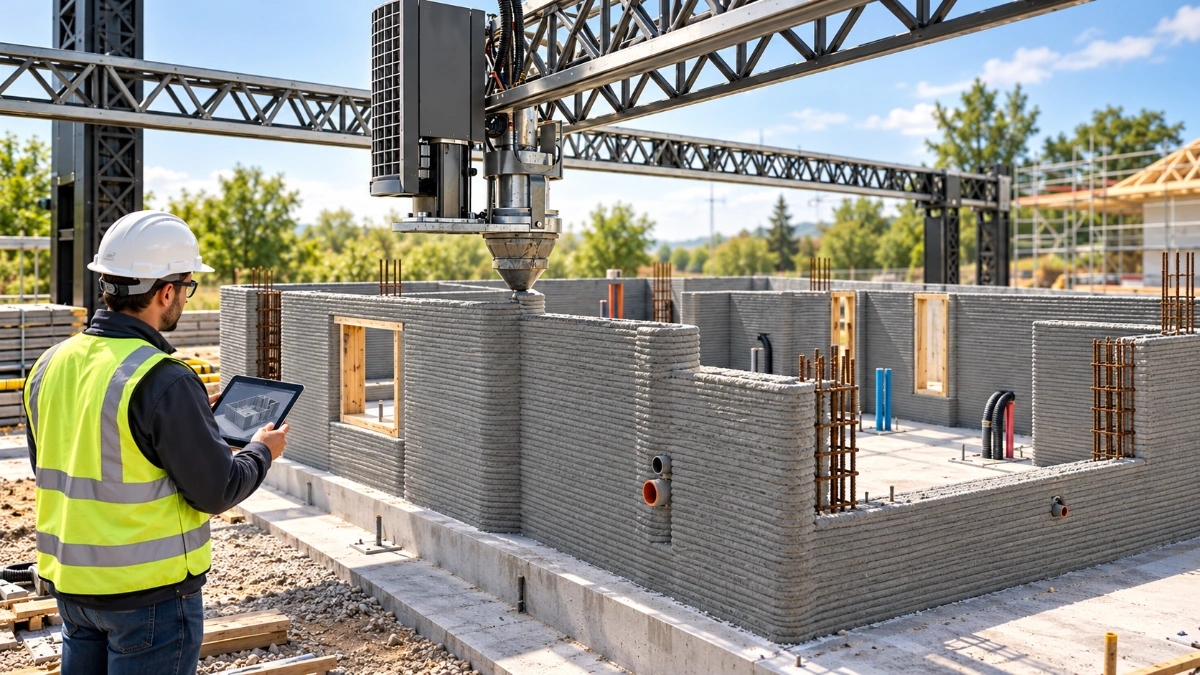
The phrase 3D printed house can create the impression that a machine arrives on site and produces a complete habitable building. In practice, construction-scale 3D printers normally perform a much narrower task: they follow a digital toolpath and deposit cementitious material layer by layer to form walls or wall components.
Depending on the system, the printed material may form the structural wall, part of a reinforced wall system, two printed shells with cavities between them, permanent formwork later filled with grout or concrete, or prefabricated printed elements assembled on site.
The rest of the building still has to be constructed. This is the central distinction behind many viral claims. A wall may be printed in hours; a finished, serviced and inspected house still requires multiple conventional trades and approvals.
The basic process: digital model to physical wall
Extrusion-based 3D concrete printing converts digital geometry into a path followed by a printer nozzle:
Digital model → print path → material preparation → pumping → extrusion → layer-by-layer wall construction
The material must remain workable enough to move through the mixer, pump, hose and nozzle, yet stiffen quickly enough after extrusion to retain its shape and support the layers above.
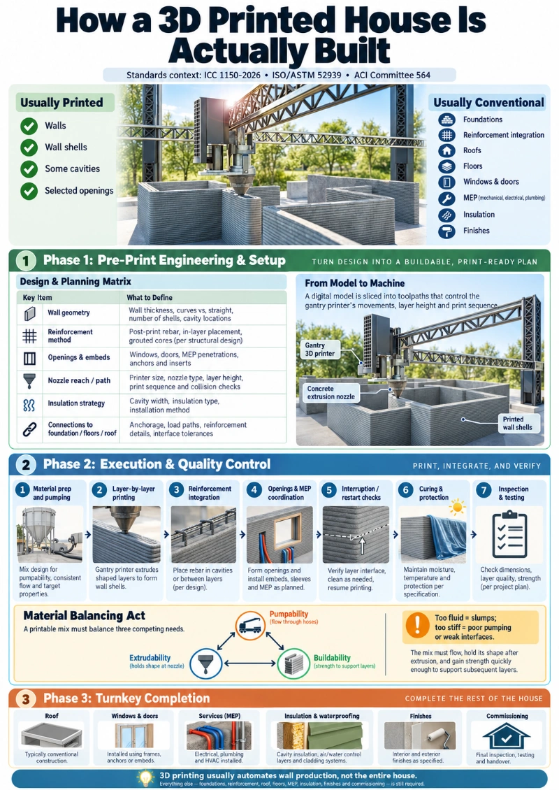
Phase 1: Pre-Print Engineering & Setup
Step 1: Design the building for the printing system
A printed building cannot simply be detailed exactly like a conventional masonry or reinforced-concrete building and sent to the printer. The design has to match the selected printing process, nozzle, wall topology, structural strategy and building interfaces.
| Design item | What must be defined before printing |
|---|---|
| Wall geometry | Wall thickness, curves versus straight runs, number of shells, cavity locations and permissible geometry. |
| Reinforcement method | Vertical bars, grouted cores, in-layer reinforcement, fibers or reinforced infill, according to the structural design. |
| Openings and embeds | Windows, doors, sleeves, MEP penetrations, anchors, inserts and other interruptions to the print path. |
| Nozzle reach and path | Printer size, nozzle geometry, layer height, print sequence, access and collision avoidance. |
| Insulation strategy | Cavity width, insulation location, continuity, installation method and building-envelope interfaces. |
| Connections | Anchorage and load transfer to foundations, floors and roof systems, including tolerances and reinforcement continuity. |
There is no single universal “3D printed wall.” ICC 1150-2026 addresses multiple layered wall configurations, including single-shell, multi-shell and reinforced-core arrangements, with or without conventional reinforcement or infill.
Step 2: Build and survey the foundation
For many systems, printing begins above a conventionally constructed foundation or slab. Before printing starts, the site team needs accurate geometry and control points because the printer's digital coordinate system has to match the physical building position.
Typical checks include foundation dimensions, finished levels, wall setting-out lines, starter reinforcement, connection details, anchor locations and service penetrations. A small error at the first layer can become a repeated geometry error up the full wall height.
Step 3: Install and calibrate the printer
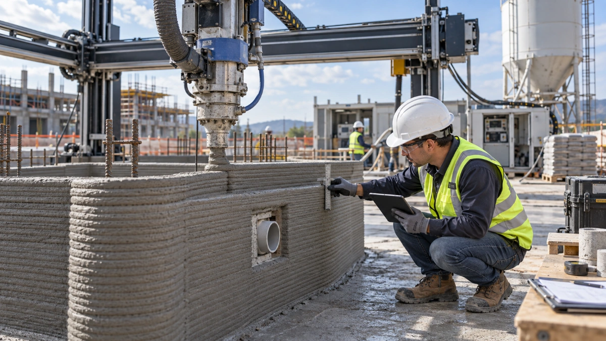
Construction printers may use gantry systems, robotic arms or other automated motion platforms. Whatever the configuration, the printer has to be positioned, levelled and calibrated so that the physical nozzle corresponds to the digital model.
The printing zone must also be coordinated with batching, mixing, pumping, hoses, material storage, controls and operator access. On a real site, the printer is part of a production system rather than a stand-alone machine.
Phase 2: Execution & Quality Control
Step 4: Prepare the printable cementitious material
The material is often called “concrete,” but printable formulations vary. Some are closer to fine-aggregate concrete or mortar, while other systems use larger aggregate or proprietary cementitious blends.
The material balancing act
| Pumpability The mix must move reliably through the pump, hose and delivery system. | Extrudability The material must pass through the nozzle and form a continuous, controlled bead. | Buildability The deposited layers must retain geometry and support subsequent layers. |
Too fluid: the wall can slump or spread. Too stiff: pumping becomes difficult and layer interfaces may suffer. The usable mix has to balance all three properties at once.
NIST identifies the relationship between mix design, extrusion parameters, geometry, orientation and hardened structural performance as a key area for reliable design and measurement methods.
Step 5: Print the walls layer by layer
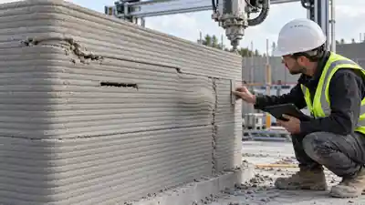
Once printing begins, the nozzle follows the programmed path while depositing a continuous bead. One pass forms a layer; the nozzle then moves upward and deposits the next.
Engineers and operators may need to monitor bead width, layer height, wall alignment, dimensional accuracy, deformation, extrusion continuity, nozzle position, surface tearing, material consistency, time between layers, environmental conditions, reinforcement, openings and interruptions.
The printer controls the path; it does not replace quality control.
Step 6: Integrate reinforcement
Reinforcement is one of the major differences between demonstration printing and engineered building construction. A moving nozzle complicates the conventional sequence of fixing a complete reinforcement cage before placement.
Different systems may use vertical reinforcing bars in cavities, grouted or concrete-filled cores, reinforcement placed between selected layers, reinforcement installed during pauses, fibers in the printed material, or printed shells acting as permanent formwork for reinforced infill.
NIST notes that some current 3D concrete printing approaches resemble reinforced masonry, with bars and grout incorporated into printed wall webbing or infill zones. Reinforcement therefore has to be treated as part of the qualified wall system, not improvised on site.
Step 7: Coordinate doors, windows and openings
The print path must deliberately account for openings. The sequence may involve stopping at opening edges, installing a lintel or other support, changing the printed geometry or combining printed and conventionally constructed elements.
A missed opening in blockwork may be relatively easy to cut later. A missed opening in a structural printed wall may affect reinforcement, load paths, insulation, moisture control or wall continuity.
Step 8: Coordinate electrical and plumbing work
Electrical and plumbing systems do not disappear because the wall is printed. Instead, they must be coordinated with the printing sequence.
Services may run inside printed cavities, through sleeves placed during printing, through deliberately formed openings, within service zones, through later penetrations where permitted, or on the completed wall surface.
If the printer passes an embed location before the item is installed, the team has to decide whether printing should stop or whether later installation is technically acceptable.
Step 9: Record and assess print interruptions
A printed wall is deliberately made from many layers, so layer interfaces are normal. A routine short interval between passes is different from a long unplanned interruption caused by equipment failure, material problems, weather or another site event.
Where an interruption could affect performance, the team should record the stop time, restart time, affected layers, surface condition, any preparation before restarting and whether additional review or testing is required.
Step 10: Cure and protect the printed material
Automation does not remove the need for hydration, curing and early-age protection. Wind, heat, direct sun, low humidity and rain can affect both the printing operation and the fresh wall.
The exposed layered geometry may also lose moisture differently from conventionally formed concrete, so curing should follow the qualified material system and project requirements rather than generic assumptions.
Phase 3: Inspection & Turnkey Completion
Step 11: Inspect and test the wall
A wall is not acceptable merely because the printer reached the end of its programmed path. Quality assurance may involve both process control during printing and verification of the completed construction.
Depending on the system and project, checks can include material batches, print parameters, dimensions, wall alignment, reinforcement, openings, connections, visible defects, interlayer quality, curing, hardened material properties and structural qualification.
Printed concrete can exhibit directional behavior because it is built in layers. Conventional cube or cylinder results may therefore describe only part of the relevant structural performance.
Step 12: Complete the rest of the building
This is the part most often omitted from viral videos. Once the printer finishes, the project continues.
- roof construction;
- upper floors where applicable;
- structural connections;
- insulation and waterproofing;
- windows and doors;
- electrical work;
- plumbing and HVAC;
- internal partitions where not printed;
- floor and wall finishes;
- fixtures and equipment;
- external works; and
- testing and commissioning.
Do not confuse printer operating time with project duration. A wall can be printed quickly while the building still requires conventional structure, envelope, MEP, finishes, inspections and handover.
What part of a 3D printed house is actually printed?
In many current projects, the walls are the principal printed component. Other projects print components off site and assemble them later, while some use printed shells as permanent formwork around conventional reinforced concrete or grout.
Floors, roofs, foundations and building services are much less likely to be produced by the same extrusion process used for the walls. When comparing projects, the better question is: What exactly was printed?
Why does 3D printing reduce formwork?
One of the strongest attractions of extrusion-based construction is the ability to create wall geometry without constructing traditional formwork for every printed surface. This can reduce labor and make curved or optimized wall shapes easier to produce.
But removing formwork creates different engineering demands: the material must support itself while fresh, reinforcement needs another installation strategy, machine setup becomes critical, and digital or printer errors can be repeated rapidly over a large quantity of work.
Is a 3D printed wall the same as cast concrete?
No. Both may use cementitious materials, but the manufacturing processes differ significantly.
Conventional concrete is normally placed into formwork and consolidated as a mass. Extrusion-based additive construction builds an element from beads and layers. Properties can therefore depend on print direction, layer orientation, delay between layers, bead geometry, moisture condition and extrusion parameters.
This process dependence is one reason standards and research focus on qualification of both the material and the manufacturing process.
What standards apply to 3D printed construction?
ICC 1150-2026 establishes minimum requirements for materials, qualification, inspection and structural design of 3D printed concrete walls and their connections using 3D Automated Construction Technology.
ISO/ASTM 52939:2023 establishes process-oriented quality-assurance requirements for additive construction of structural and infrastructure elements.
The American Concrete Institute also maintains ACI Committee 564 — 3-D Printing with Cementitious Materials, which develops and reports technical information on additive manufacturing with cement-based materials.
These standards and committees do not mean that every printing system is automatically accepted in every jurisdiction. Building-code acceptance, structural design, fire resistance, energy performance, material approval and inspection still depend on the applicable authority and qualified construction system.
How fast is a 3D printed house?
The useful distinction is between wall printing time and complete construction duration.
Wall printing can be much faster than conventional wall construction in some projects. Total project duration still includes foundations, reinforcement, structure, MEP, roofing, enclosure, finishes, inspections and commissioning.
A claim that a house was “printed in 24 hours” may refer to cumulative printer operating time or wall-production time rather than excavation-to-occupancy duration.
Is a 3D printed house cheaper?
It can be, but there is no universal saving percentage.
Potential savings may come from reduced formwork, lower wall-construction labor, automation, optimized geometry and reduced material waste. Those savings have to be weighed against printer mobilization, specialized material, pumping and mixing equipment, operators, engineering, qualification, reinforcement, maintenance and the conventional work still required to finish the building.
A wall-printing cost should therefore not be compared directly with the turnkey cost of a completed conventional house.
What can go wrong during 3D concrete printing?
Problems can arise from the material, printer, geometry or coordination process. Examples include slumping, inconsistent bead dimensions, tearing, under- or over-extrusion, nozzle drag, layer misalignment, excessive interlayer delay, poor interfaces, dimensional drift, blocked pumping equipment, omitted reinforcement, missed MEP embeds and unplanned interruptions.
A cosmetic surface defect and a suspected structural interlayer defect are not the same problem, so defects should be classified and assessed rather than treated as one generic category.
Does 3D printing eliminate site engineers and inspectors?
No. It changes what they inspect.
Site engineers and QA/QC teams may spend less time supervising repetitive wall-laying operations and more time checking digital setting out, printer calibration, material production, print geometry, reinforcement, interfaces, embeds, interruptions, testing, traceability and deviations from the qualified system.
Automation can increase the importance of records because one repeated machine or digital error can affect a large quantity of work very quickly.
The engineering takeaway
A 3D printed house is best understood as a hybrid construction project. The printer can automate wall production and create geometry that would be difficult or expensive using traditional formwork, but the printed wall remains part of a larger structural, building-envelope and services system.
For engineers, the most useful questions are not simply how fast the printer moves. They are: What is actually being printed, how is it reinforced, how is it inspected, how does it connect to the rest of the building, and how is its performance verified?
References
NIST — Additive Manufacturing with Cement-based Materials
ICC — ICC 1150-2026 Standard for Automated Construction Technology for 3D Printing Walls
ISO — ISO/ASTM 52939:2023 Additive manufacturing for construction
ACI Committee 564 — 3-D Printing with Cementitious Materials