
Inspection and Test Plan for Method Statement: Pneumatic Testing of Oil & Gas Piping Systems
AI-assisted inspection and test plan connected to a method statement, with PDF and Excel export.
More than a static template
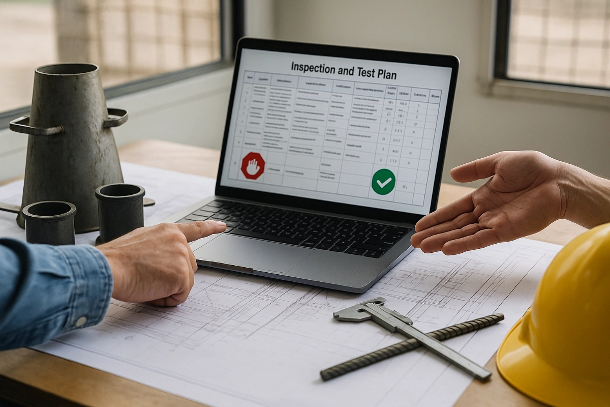
Unlike a downloadable Word or PDF template, this ITP is an AI-assisted editable starting point directly connected to its method statement. Every inspection activity, hold point, and acceptance criterion is structured and ready to adapt to your project.
- AI-assisted customization — Tailor inspection activities and acceptance criteria to your specific project scope.
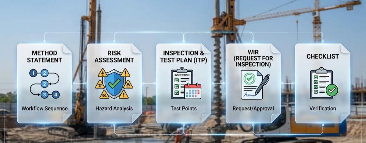
- Linked method statement — This ITP is connected to the corresponding method statement describing the work sequence.
- Multiple export formats — Download as a formatted PDF or editable Excel spreadsheet.
- Editable starting point, not a final document — Review and verify all content against your project specifications and standards before use.
What you can customize
When you save this ITP to your account, every inspection row becomes editable. You can add, remove, or modify:
- Inspection activity — Description of what is being inspected.
- Inspection type — Hold point (H), Witness point (W), Review (R), or Monitor (M).
- Responsibility — Contractor, subcontractor, engineer, or client.
- Frequency — How often the inspection occurs.
- Acceptance criteria — Referenced standard or specification requirement.
- Records — Forms, test reports, or checklists required as evidence.
Why this ITP is used
To control and verify each critical stage of pneumatic testing, ensuring safety and compliance with codes and project specs.
Who uses this inspection and test plan
Contractor Supervisors, QC Inspectors, HSE Officers, and Client/Engineer Representatives.
When this ITP is prepared and submitted
From pre-test documentation review through boundary verification, pressurization increments, hold/leak checks, depressurization, and reinstatement.
Who receives or approves this ITP
Client/Engineer Representative for review and approval before testing.
Inspection scope
Covers document reviews, boundary walkdowns, instrument calibration, exclusion zone verification, staged pressurization, leak examination, depressurization, and reinstatement checks.
Typical hold, witness, and review points
Instrument calibration check, exclusion zone/permit verification, 100% Pt hold and leak examination, and dossier approval.
Typical inspection records
Approved test pack, calibration certificates, PRV setting, pressure/time logs, leak survey sheets, witness/hold point signatures, reinstatement checklists, and final certificate.
Important approval note
This ITP is an AI-assisted editable starting point, not a pre-approved document. Before use on any project, all inspection activities, hold points, and acceptance criteria must be reviewed and approved by the relevant parties (superintendent, principal contractor, or client representative) in accordance with your contract and project quality plan.
Always verify acceptance criteria against your applicable drawings, specifications, and regulatory requirements. Hold points must be confirmed with the relevant authority before work proceeds past that point.
Inspection and test plan
| Activity | Inspection / Test | Acceptance Criteria | Responsibility | Record |
|---|---|---|---|---|
| Test pack review and approval | Verify P&IDs/isos, boundary list, Pt calc, risk assessment, PRV sizing/setting, calibration certificates. | Documents approved; Pt and scope authorized; instruments valid. | Contractor QC / Client Rep | Approved test pack; ITP sign-off |
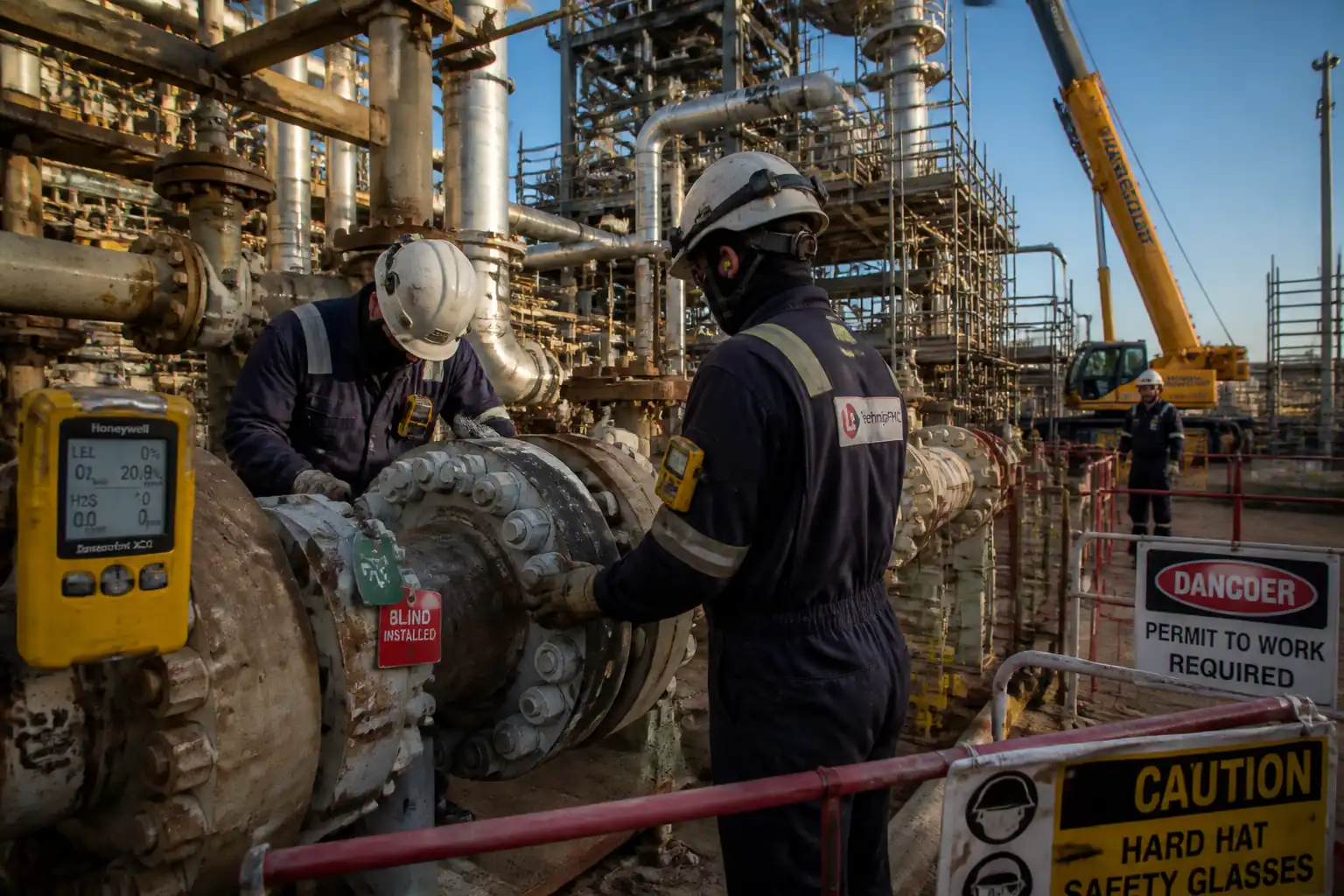
| Pre-test boundary walkdown | Physical verification of blinds/spades/valves; vents and relief path; tags installed. | Boundaries match drawings; components rated and secure. | Contractor QC + Supervisor + Client (Witness) | Walkdown checklist; photos |
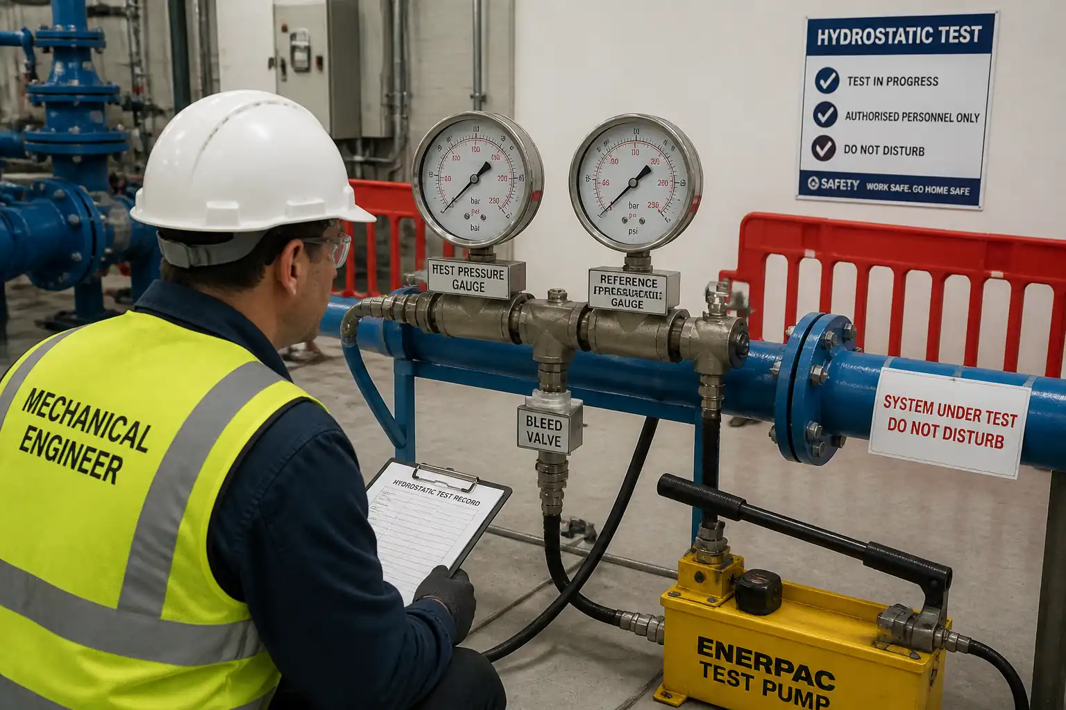
| Instrument calibration verification | Check gauge ranges vs Pt; calibration date; PRV set-and-seal cert; regulator condition. | Gauges valid; Pt within 30–80% FS; PRV set ≤ 110% Pt. | Contractor QC (Hold) | Calibration certificates; PRV set sheet |
| Drying/purge verification (if applicable) | Measure dew point and/or O2 concentration after purge. | Dew point and O2 within specified limits. [Verify] | Supervisor / HSE / Client (Witness) | Analyzer log; purge record |
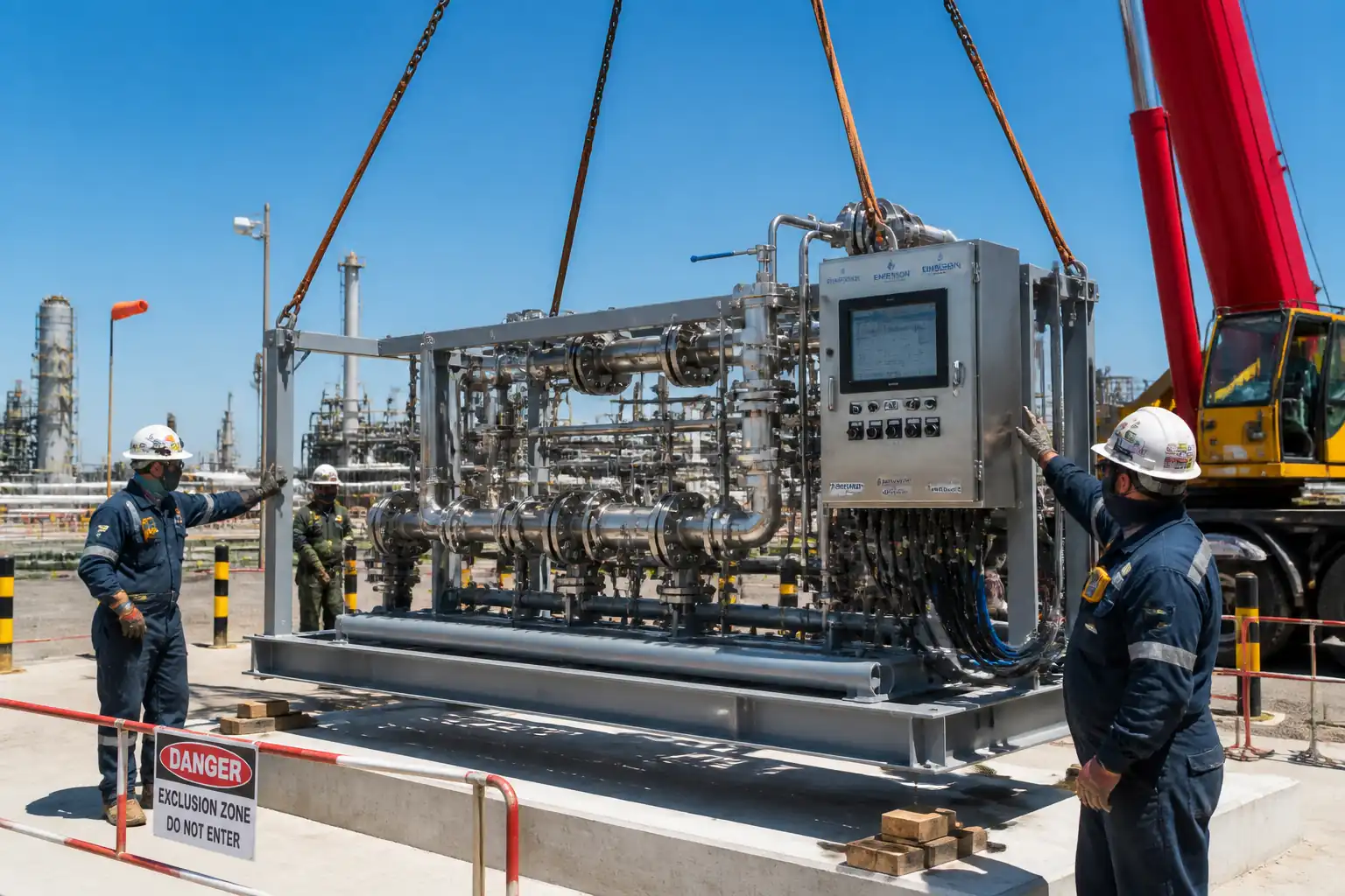
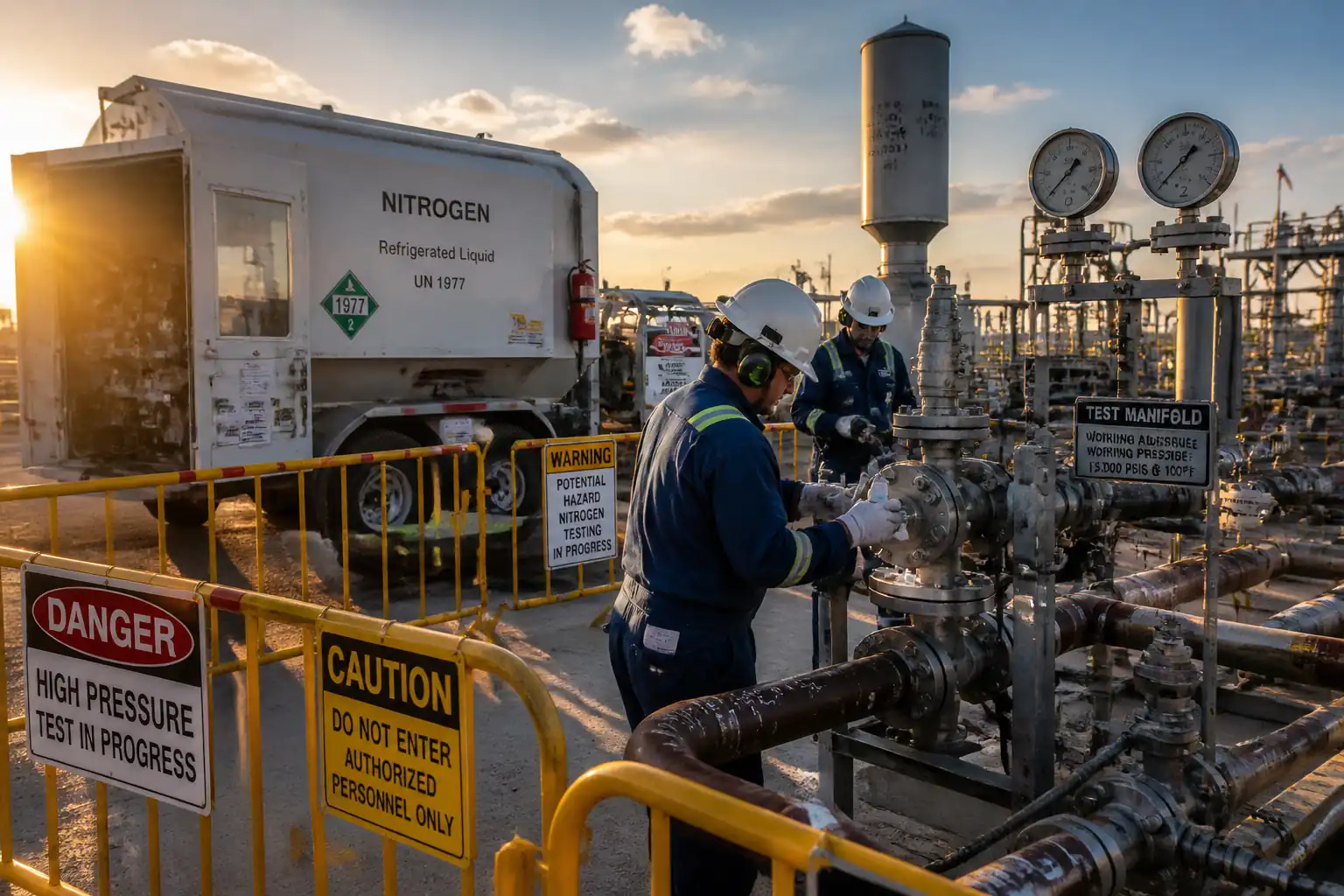
| Exclusion zone and PTW confirmation | Check barricades, signage, access control, gas monitors, comms, emergency plan. | PTW active; zone established per risk assessment. | HSE Officer (Hold) | PTW; HSE checklist |
| Pressurization to 10% Pt | Monitor gauges; visual/audible leak check at manifold. | Stable pressure; no signs of distress. | Supervisor / QC | Pressure log |
| Pressurization to 50% Pt | Hold 10 min; leak survey with soap solution/ultrasonic at accessible points. | No visible leaks; stable readings. | Supervisor / QC / Client (Witness) | Leak survey sheet; witness sign |
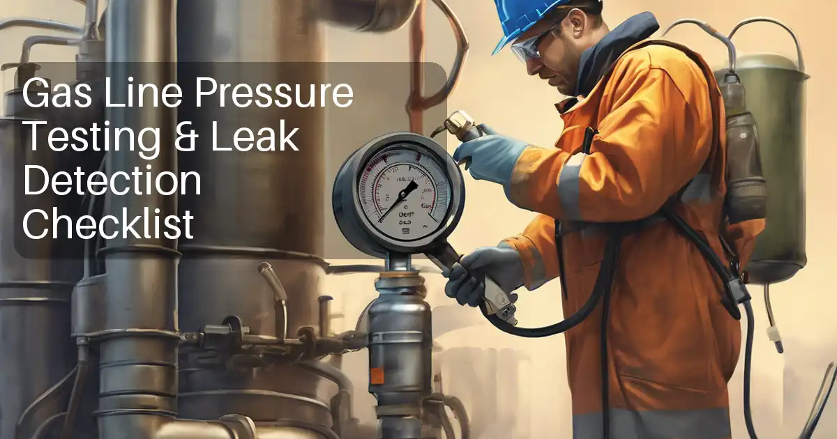
| Pressurization to 100% Pt and hold | Raise to Pt; stabilize; detailed leak check per ASTM E515; temperature verification vs MDMT; pressure/time logging. | No bubbles; no permanent deformation; pressure stable after temp correction. | Supervisor / QC / Client (Hold) | Chart/Logger data; ITP checklist; hold-point signature |
| Controlled depressurization | Vent via silencer to safe area; confirm zero pressure on two gauges. | Pressure = 0 barg; no abnormal events. | Supervisor / HSE (Witness) | Depressurization record |
| Reinstatement check | Remove blinds; restore configuration; remove support pins; instrument reinstatement. | System matches P&ID/isometric; no foreign materials left. | QC / Client (Witness) | Reinstatement checklist; as-built markups |
| Dossier compilation and approval | Verify completeness of records and traceability. | Signed Pressure Test Certificate; all attachments filed. | Contractor QC / Client | Approved dossier |
This table is a read-only public reference. Download the PDF or Excel version, or customize this ITP to edit it for your project.
Frequently asked questions
Related method statement
This Inspection and Test Plan is associated with the Method Statement: Pneumatic Testing of Oil & Gas Piping Systems method statement, which describes the step-by-step construction sequence, resources, materials, equipment, safety controls, and environmental controls for this activity.
View the Method Statement: Pneumatic Testing of Oil & Gas Piping Systems method statement →Continue with related inspection, method statement, article, and checklist resources.