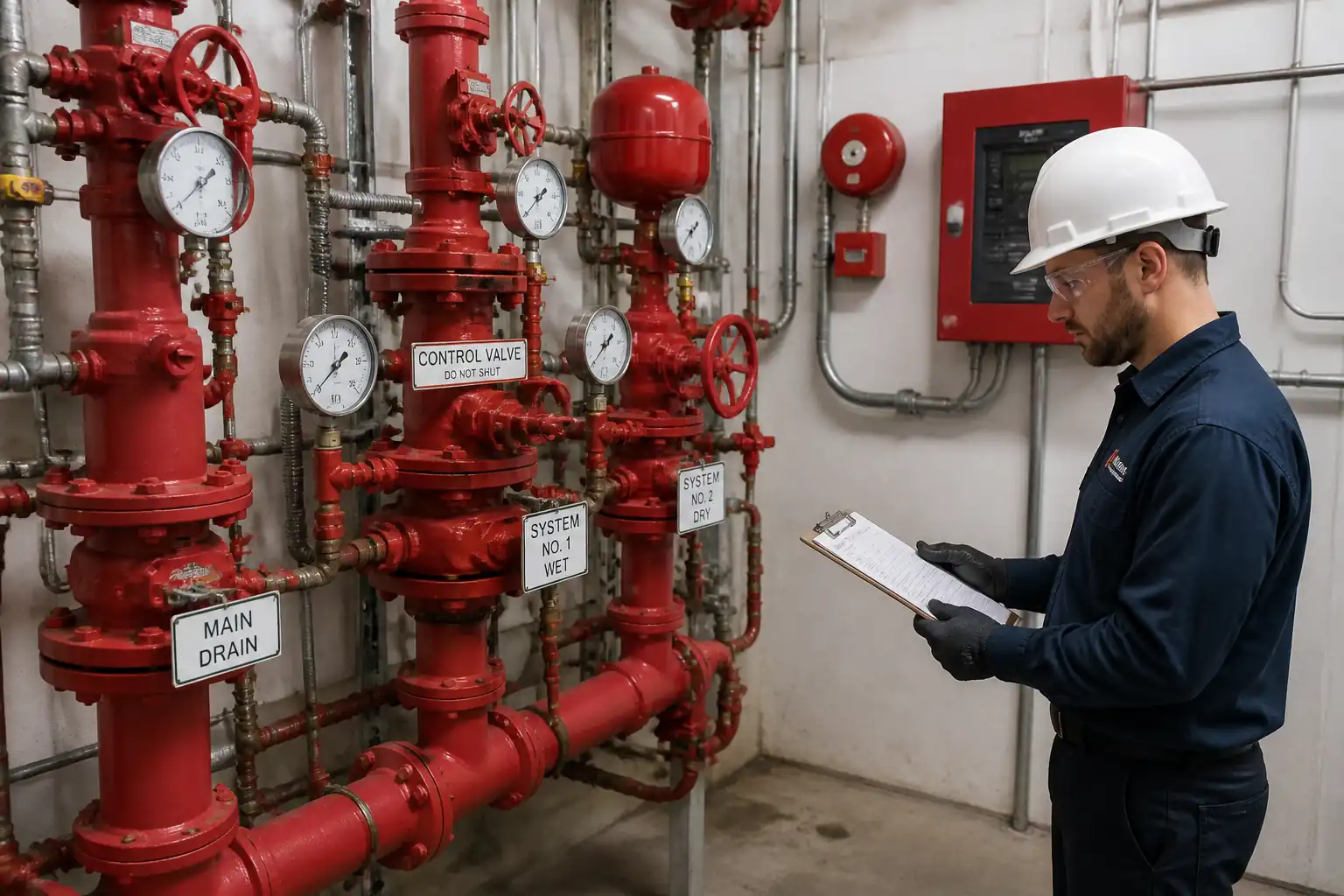

Method Statement: Pre-Commissioning and Testing of Wet, Dry, and Pre-Action Sprinkler Systems – Method Statement
AI-assisted method statement with matching ITP, PDF download, and Excel export.
More than a static template
Unlike a downloadable Word or PDF template, this method statement is an AI-assisted editable starting point connected directly to a matching Inspection and Test Plan. Every section is structured, project-adaptable, and ready to export.
- AI-assisted drafting — Customize every section with AI for your specific project scope.
- Linked ITP — A matching inspection and test plan is generated alongside the method statement.
- Multiple export formats — Download as a formatted PDF or editable Excel spreadsheet.
- Editable starting point, not a final document — Review, verify, and adjust all content against your project requirements before use.
Static template vs. Quollnet workflow
| Feature | Static template | Quollnet |
|---|---|---|
| Project-specific content | Manual fill-in required | AI-assisted customization |
| Linked ITP | Separate document, no link | Matching ITP included |
| Export formats | Usually PDF only | PDF and Excel |
| Structured sections | Free-form layout | 13 standardized sections |
| Saved to your account | Local file only | Cloud-saved, reusable |
| Content accuracy | You verify everything | AI-assisted, you still verify |
| Cost | Often free but time-intensive | Free to customize and download |
What you can customize
When you save this method statement to your account, every section becomes editable. The following 13 sections are included:
- Scope — Defines the activity and its boundaries.
- References — Standards, specifications, and drawings.
- Responsibilities — Roles and accountabilities.
- Resources — Labour, plant, and equipment summary.
- Materials — Materials and compliance requirements.
- Equipment — Tools and equipment details.
- Prerequisites — Hold points and pre-conditions.
- Method sequence — Step-by-step construction sequence.
- Safety controls — HSE risk controls and PPE.
- Environmental controls — Environmental mitigation measures.
- QA/QC — Quality inspection and test requirements.
- ITP — Inspection and Test Plan table (has its own page).
- Attachments — Referenced drawings and documentation.
Why this method statement is used
This method statement is used to define and communicate the approved procedure for carrying out method statement: pre-commissioning and testing of wet, dry, and pre-action sprinkler systems on site. It ensures the work is planned in advance, the correct resources and controls are in place, and all personnel understand responsibilities, sequence, quality requirements, and safety controls before work begins. It aligns site execution with the documented scope and acceptance expectations.
Who uses this method statement
This method statement is used by contractors, site supervisors, project engineers, QA/QC engineers, HSE officers, consultants, and client representatives. It serves as a shared reference for planning, execution, supervision, inspection, and approval of the activity on site.
When it is prepared and submitted
The method statement is prepared before the work activity starts and submitted as part of the pre-construction documentation package for review and approval.
Who reviews or approves it
The method statement is usually submitted to the client representative, consultant, resident engineer, or project management consultant for review and approval before the work commences.
Important approval note
This method statement is an AI-assisted editable starting point, not a pre-approved document. Before use on any project, all content must be reviewed and approved by the relevant parties (superintendent, principal contractor, or client representative) in accordance with your contract and project quality plan.
For example: if your specification requires a departure from a referenced standard, that departure must be documented and approved separately — this method statement will not capture that automatically. Always verify against your applicable drawings, specifications, and regulatory requirements.
Method statement content
Scope
Overview
This method statement defines the pre-commissioning and acceptance testing procedures for wet, dry, and pre-action automatic sprinkler systems, including:
- Hydrostatic pressure testing of aboveground sprinkler piping
- Alarm valve trip and waterflow alarm testing (local and fire alarm interface)
- Dry pipe and pre-action valve functional trip and water delivery performance tests
- Main drain flow verification on each riser
- Supervisory signal checks for valves, air/nitrogen pressure, water levels, and pump auto-start where applicable
Systems Covered
- Wet pipe sprinkler systems and wet alarm valves
- Dry pipe sprinkler systems (with accelerators as applicable)
- Single- and double-interlock pre-action systems with detection interfaces (NFPA 72)
- Associated risers, floor control assemblies, inspectors’ test connections, main drains, and interlocks with the Fire Alarm Control Panel (FACP) and fire pump/transfer switches
Exclusions
- Underground mains flushing and testing beyond verification of prior acceptance (performed under NFPA 24 scope)
- Fire pump performance testing (covered under NFPA 20 commissioning; only interface verification is included)
- Long-term periodic inspection/testing (NFPA 25 post-handover)
Objectives
- Demonstrate system integrity (no leakage), correct functionality of valves and alarms, and baseline flow characteristics per design intent and applicable codes.
- Produce contract records suitable for submission to the Engineer, Insurer/AHJ, and Client for handover.
Constraints/Assumptions
- All concealed pipework requiring hydrostatic testing is accessible or has been pneumatically leak-checked prior to concealment where hydrostatic testing was impracticable [Verify per project specifications].
- Testing pressures, water discharge routing, and witnessing requirements are coordinated and approved prior to testing.
References
| Document Type | Reference / Number | Revision | Notes |
|---|---|---|---|
| Standard | NFPA 13: Installation of Sprinkler Systems (latest adopted edition) | Hydrostatic testing, alarm devices, dry/pre-action performance tests; acceptance time for waterflow alarm within 90 s; specific limits [Verify per adopted edition]. | |
| Standard | NFPA 25: Inspection, Testing, and Maintenance of Water-Based Fire Protection Systems | Baseline main drain data and periodic tests reference for post-handover. | |
| Standard | NFPA 72: National Fire Alarm and Signaling Code | Waterflow, supervisory, and trouble signal verification; time-to-alarm performance. | |
| Standard | NFPA 20: Fire Pumps | Pump auto-start on pressure drop during main drain test; acceptance testing coordination. | |
| Standard | NFPA 24: Private Fire Service Mains and Their Appurtenances | Prerequisite flushing and hydrotest for mains feeding risers. | |
| Standard | BS EN 12845: Fixed firefighting systems — Automatic sprinkler systems — Design, installation and maintenance | Use only where contractually specified; align test pressures and alarm timings accordingly [Verify per project specifications]. | |
| Standard | ISO/IEC 17025 (Calibration of measuring instruments) | Calibration traceability for gauges, pressure transducers, stopwatches, and flow meters. | |
| Standard | ISO 45001 / Local HSE Regulations | Permits to work, pressure testing safety, energy isolation, environmental discharge [Verify per project HSE plan and local regulations]. |
Responsibilities
| Role | Responsibility | Name / Party |
|---|---|---|
| Project Manager | Project Manager | Main Contractor |
| Lead Fire Protection Engineer | Lead Fire Protection Engineer | Main Contractor |
| Commissioning Manager | Construction/Commissioning Manager | Main Contractor |
| QA/QC Inspector | QA/QC Inspector | Main Contractor |
| HSE Officer | HSE Officer | Main Contractor |
| Sprinkler Subcontractor Supervisor | Sprinkler Specialist Supervisor | Specialist Subcontractor |
| Fire Alarm Vendor | Fire Alarm Vendor Engineer | Specialist Subcontractor |
| Engineer/Inspector | Client/Consultant Rep / AHJ | Client/AHJ |
Resources
| Resource Type | Description | Quantity | Remarks |
|---|---|---|---|
| Personnel | 2 x sprinkler fitters + 1 x supervisor | 3 | |
| Personnel | 1 x QA/QC inspector | 1 | |
| Personnel | 1 x HSE officer | 1 | |
| Personnel | 1 x Fire alarm engineer + 1 x technician | 2 |
Materials
| Material | Specification / Grade | Quantity | Remarks |
|---|---|---|---|
| Water | Clean, non-corrosive | As required | |
| Tags/Seals | Durable, legible | Set per riser | |
| Air/Nitrogen | Oil-free, dry to -40°C dew point typical [Verify] | As required | |
| Leak detection fluid | Non-staining | As required |
Equipment
| Equipment | Capacity / Type | Quantity | Inspection Required |
|---|---|---|---|
| Hydro pump | Up to 250 psi (1.7 MPa) continuous | 1 | Pre-use inspection, calibration certs |
| Analog/digital gauges | 0–300 psi (0–2.1 MPa) | 4 | ISO 17025 traceable |
| Stopwatch / Logger | 0.1 s resolution | 2 | Functional check |
| Hoses/Manifold | 250 psi WWP minimum | Set | Visual for damage |
| Compressor / N2 pack | 0–60 psi supervisory range | 1 | Regulator test, cylinders in date |
| Radios | As required | Battery check |
Prerequisites
- Approved shop drawings, hydraulic calculations, valve schedules, and cause-and-effect matrix.
- As-built verification of pipework, hangers/supports, valves, trim, drains, inspectors’ test connections, and signage complete.
- Underground mains flushing and hydrotest accepted with records available (NFPA 24).
- Calibration certificates for gauges/loggers within validity; instrument IDs listed in test pack.
- HSE: Pressure testing risk assessment approved; permits (hot work if cutting required for vents, confined space if valve rooms restricted), impairment permit for fire protection (notify building management, monitoring station, and AHJ as required) [Verify per project HSE plan and local regulations].
- Temporary drains/hoses routed to approved discharge points with sediment control; spill kits available.
- Fire alarm panels powered and in “test mode”; responsible parties informed; fire pump in auto unless otherwise directed for specific tests and coordinated with Engineer.
- Isolation plans, boundary valves identified and tagged; backflow preventers considered for test setup.
- Weather/temperature considered to prevent freezing; building areas protected.
- Access equipment and lighting available; lockout/tagout where needed.
- Test documentation templates prepared (hydrostatic, alarm/trip, main drain, punch list).
Method Sequence
| Step | Activity | Description | Responsibility | Inspection / Hold Point |
|---|---|---|---|---|
| 1 | Pre-test inspection (all systems) | Walkdown each riser/zone, verify completeness, valve positions (normally closed/open), trim orientation, drains, vents at high points, gauges installed, ITC (inspector’s test connection) and main drain accessible. Record any defects. | Sprinkler Supervisor / QA-QC | Joint inspection with Client/Engineer |
| 2 | Wet system hydrostatic test setup | Isolate riser/zone. Connect hydro pump to low point, install two calibrated gauges (pump discharge and remote high point). Vent air at high points while filling slowly with water. | Sprinkler Supervisor | QA/QC to verify instruments |
| 3 | Hydrostatic test (aboveground piping) | Pressurize to 200 psi (1.38 MPa) or 50 psi (0.34 MPa) above maximum system working/static pressure, whichever is greater. Hold for 2 hours. Monitor for leakage and record readings at 15-min intervals; note ambient temperature. | Sprinkler Supervisor / QA-QC | Engineer/AHJ witness (Hold Point) |
| 4 | Optional pneumatic leak check (where hydro not yet feasible) | Apply oil-free air/N2 ≤40 psi (2.7 bar). Brush joints with leak-detection solution. Maintain for stabilization period as directed. Safety: establish exclusion zone. | Sprinkler Supervisor / HSE | QA/QC witness |
| 5 | Wet alarm valve trip and waterflow alarm | From the remote ITC, open test orifice equivalent to one sprinkler (per design K-factor). Record time from valve opening to: a) local alarm (water motor gong), b) waterflow switch activation, c) FACP alarm annunciation. | Sprinkler Supervisor / FA Engineer | Engineer witness |
| 6 | Supervisory/tamper signals | Operate valve supervisory switches (OS&Y/Tamper), low/high air pressure switches (where applicable), and water tank level/low temperature if present. Verify signal routing to FACP and BMS if specified. | FA Engineer / Sprinkler Supervisor | QA/QC witness |
| 7 | Main drain test (each riser) | Record static pressure at riser. Fully open main drain for 2 minutes (or until stabilization). Record residual pressure at 30 s intervals; then close drain slowly and record time to recovery of static. | Sprinkler Supervisor / QA-QC | Engineer witness (as required) |
| 8 | Dry pipe valve pre-test | Verify set pressures (air-to-water ratio per manufacturer), accelerators in service, priming water levels correct, drains closed, quick-opening device (if any) tested per OEM. | Sprinkler Supervisor | QA/QC witness |
| 9 | Dry system trip and water delivery test | Open remote ITC fully. Record: a) valve trip time, b) local alarm, c) FACP alarm, d) time to water at ITC. Repeat if required with QOD/accelerator active and inactive per Engineer instructions. | Sprinkler Supervisor / FA Engineer | Engineer/AHJ witness (Hold Point) |
| 10 | Pre-action functional test (single- or double-interlock) | Prove detection logic: activate designated detector(s) per cause-and-effect; verify valve energizes only with required detection/actuation and (if double-interlock) loss of air. Record sequence times to: solenoid energize, valve open, local alarm, FACP alarm, water at ITC. | FA Engineer / Sprinkler Supervisor | Engineer/AHJ witness |
| 11 | Restoration and resets | After each test, close drains, reset valves, restore air/N2 to supervisory pressure, verify free movement of clappers/solenoids, clear alarms, remove lockouts where authorized, and return systems to normal. Update impairment log. | Sprinkler Supervisor / FA Engineer | QA/QC check |
| 12 | Documentation & handover | Compile signed test records, calibration certificates, redlines/as-builts, O&M, and training logs. Submit to Engineer for approval. | QA/QC / Project Manager | Engineer review |
Health, Safety, and Environment (HSE) – Safety Controls
Key Task-Specific Hazards and Controls
1) Hazard: High-pressure hydrostatic testing (pipe/fixture failure)
- Likely consequence: Sudden rupture, flying debris, blunt trauma, water jet injury
- Engineering/procedural control: Pressure relief valve on test manifold; pressurize gradually; barricade/exclusion zone; use rated hoses/fittings; no personnel in line-of-fire; use two calibrated gauges; maintain communication; stop at any abnormal noise/movement.
- Required PPE: Safety helmet, eye protection (face shield for operators), gloves, safety boots, hearing protection if gongs active.
- Collective preventive measure: Physical barriers and signage; remote reading where possible.
- Inspection/permit/supervision: Pre-use equipment inspection; calibration certs; Pressure Testing Permit; competent supervisor present [Verify per project HSE plan and local regulations].
2) Hazard: Pneumatic testing (stored energy)
- Likely consequence: Explosive release causing severe injury
- Engineering/procedural control: Minimize pressure (≤40 psi); prohibit unattended pressurization; use nitrogen/air with regulator and relief; designate danger zone; do not use compressed oxygen.
- Required PPE: Face shield, gloves, helmet, boots.
- Collective preventive measure: Barriers; lockable regulator; pressure indication at fill point and remote.
- Inspection/permit/supervision: Specific RA; permit to pressurize; supervisor and HSE oversight.
3) Hazard: Uncontrolled water discharge/flooding
- Likely consequence: Slip hazards, electrical contact, property damage
- Engineering/procedural control: Pre-plan drains/hoses to approved sumps; protect electrical equipment; deploy wet vac/berms; throttle closing to avoid water hammer.
- Required PPE: Waterproof boots, gloves.
- Collective preventive measure: Floor signage, spill response kits.
- Inspection/permit/supervision: Impairment permit; area inspection prior to test; housekeeping checks.
4) Hazard: Working at height to access valves/gauges
- Likely consequence: Falls from ladders/platforms
- Engineering/procedural control: Use certified platforms; maintain 3 points of contact; avoid overreach; secure tools.
- Required PPE: Fall arrest where required, helmet with chin strap.
- Collective preventive measure: Edge protection; MEWP with trained operator.
- Inspection/permit/supervision: MEWP inspection; Working at Height permit.
5) Hazard: Electrical/fire alarm interfaces
- Likely consequence: Electric shock, false dispatch or nuisance alarms
- Engineering/procedural control: Coordinate with FA vendor; place FACP in test mode; verify isolation of non-test circuits.
- Required PPE: Standard electrical-safe gloves if opening panels (qualified personnel only).
- Collective preventive measure: Lockable panel access; signage at panel.
- Inspection/permit/supervision: Electrical work permit if panel internal work; FA vendor supervision.
6) Hazard: Noise from water motor gongs/alarms
- Likely consequence: Hearing damage, distraction
- Engineering/procedural control: Notify workforce; limit exposure time; use hearing protection.
- Required PPE: Hearing protection.
- Collective preventive measure: Zone isolation and scheduling.
- Inspection/permit/supervision: HSE monitoring for noise.
7) Hazard: Pressure/vacuum injury during drainage
- Likely consequence: Hose whip, sudden movement
- Engineering/procedural control: Secure hoses; open/close valves slowly; depressurize before disconnection.
- Required PPE: Eye protection, gloves.
- Collective preventive measure: Use whip-checks and restraints.
- Inspection/permit/supervision: Supervisor sign-off before disconnecting.
8) Hazard: Confined/poorly ventilated valve rooms
- Likely consequence: Heat stress, lack of egress
- Engineering/procedural control: Keep doors unlatched; maintain ventilation; occupancy control; emergency lighting.
- Required PPE: Standard PPE, headlamp as needed.
- Collective preventive measure: Access control and monitoring.
- Inspection/permit/supervision: Confined space assessment if applicable [Verify per project HSE plan].
Environmental Controls
- Water discharge management: Route test water to sanitary drain where permitted; otherwise to temporary tanks. Prevent discharge to sensitive receptors. Use sediment socks and screens to capture rust scale.
- Chlorinated water: If discharging to surface, dechlorinate per local requirements [Verify per local regulations].
- Spill prevention: Bund pump and manifolds; provide drip trays; immediate cleanup of leaks.
- Noise: Schedule alarm gong tests during permitted hours; provide hearing protection zones.
- Waste: Collect used tags, broken gauges, and consumables; dispose via approved waste stream. Return gas cylinders to supplier.
- Energy: Shut down compressors when not in use; avoid idling generators.
- Documentation: Keep discharge permits/approvals on file and available for inspection.
Quality Assurance / Quality Control
- Instruments: All gauges and time devices to be identified by serial number with calibration certificates (ISO/IEC 17025) included in the test pack.
- Test identification: Assign unique test numbers per riser/zone; drawings to indicate test boundaries and vent/drain points.
- Hold/witness points: Hydrostatic test of each zone (Hold – Engineer/AHJ), Dry and Pre-action trip tests (Hold – Engineer/AHJ), Fire alarm interface (Witness – Engineer), Main drain baseline (Witness – Engineer as required).
- Measurement resolution: Pressure gauges minimum 1 psi resolution; time devices 0.1 s resolution; temperature recorded where relevant.
- Nonconformance: Any leakage, failure to meet time criteria, or abnormal pressure/flow to be recorded as NCR with corrective action and re-test plan.
- Records: Pre-test checklists, hydro test sheets, trip/alarm test sheets, main drain data, restoration checklist, calibration certificates, permits, photos/videos, and witness signatures.
- Acceptance summary: Compliance with NFPA 13/72/20/24 (or BS EN 12845 if specified), design documents, and project specifications. Deviations require Engineer’s written approval.
- Handover: Assemble a test dossier with as-builts and hydraulic placards; provide operator training and sign attendance.
Attachments
- Sample Hydrostatic Test Sheet (with dual-gauge readings and temperature notes)
- Alarm/Trip Test Record Templates (wet, dry, pre-action)
- Main Drain Test Record Template (static/residual/recovery)
- Pre-test Walkdown Checklist
- Restoration Checklist
- Instrument Calibration Certificates (ISO/IEC 17025)
- Approved Drawings: Riser diagrams, valve schedules, hydraulic placards
- Approved Risk Assessment and Permits (Impairment PTW, Pressure Testing PTW)
- OEM Data Sheets and Setting Instructions (dry/pre-action valves, accelerators, solenoids)
- Cause-and-Effect Matrix for Fire Alarm Interfaces
This content is a read-only public reference. Download or customize to get an editable version.
ITP preview
The first inspection activities from the linked ITP for Method Statement: Pre-Commissioning and Testing of Wet, Dry, and Pre-Action Sprinkler Systems:
| Activity | Inspection / Test | Acceptance Criteria | Responsibility | Record |
|---|---|---|---|---|
| Pre-test walkdown | System completeness verification | All components installed, labeled; valves in required positions; defects closed. | QA/QC Inspector / Sprinkler Supervisor | Pre-test checklist signed by parties |
| Instrumentation verification | Calibration and range check | Gauges/loggers within calibration; range suitable for test pressures/time. | QA/QC Inspector | Calibration certificates, instrument list |
| Hydrostatic test setup | Filling/venting verification | Air expelled; two gauges installed; relief valve present. | Sprinkler Supervisor / QA/QC | Setup verification sheet |
Showing 3 of 12 inspection activities. View full ITP →
Related Inspection and Test Plan
An Inspection and Test Plan (ITP) is available for Method Statement: Pre-Commissioning and Testing of Wet, Dry, and Pre-Action Sprinkler Systems. The ITP defines the inspection activities, acceptance criteria, hold and witness points, responsible parties, and records required to verify the work described in this method statement.
View the Method Statement: Pre-Commissioning and Testing of Wet, Dry, and Pre-Action Sprinkler Systems ITP →