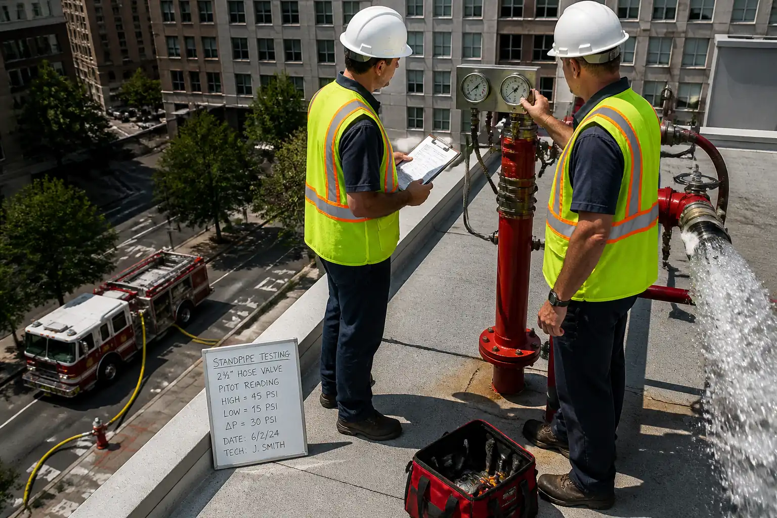

Inspection and Test Plan for Method Statement: Commissioning of Standpipe Systems (Wet and Dry) – Flow, Pressure, and Fire Brigade Inlet Testing
AI-assisted inspection and test plan connected to a method statement, with PDF and Excel export.
More than a static template
Unlike a downloadable Word or PDF template, this ITP is an AI-assisted editable starting point directly connected to its method statement. Every inspection activity, hold point, and acceptance criterion is structured and ready to adapt to your project.
- AI-assisted customization — Tailor inspection activities and acceptance criteria to your specific project scope.
- Linked method statement — This ITP is connected to the corresponding method statement describing the work sequence.
- Multiple export formats — Download as a formatted PDF or editable Excel spreadsheet.
- Editable starting point, not a final document — Review and verify all content against your project specifications and standards before use.
What you can customize
When you save this ITP to your account, every inspection row becomes editable. You can add, remove, or modify:
- Inspection activity — Description of what is being inspected.
- Inspection type — Hold point (H), Witness point (W), Review (R), or Monitor (M).
- Responsibility — Contractor, subcontractor, engineer, or client.
- Frequency — How often the inspection occurs.
- Acceptance criteria — Referenced standard or specification requirement.
- Records — Forms, test reports, or checklists required as evidence.
Why this ITP is used
To ensure standpipe systems meet NFPA, design, and AHJ requirements before handover, documenting all inspections and tests.
Who uses this inspection and test plan
Contractor QA/QC, Commissioning team, Consultant/Engineer, and AHJ/Fire Brigade as witnesses or approvers.
When this ITP is prepared and submitted
After installation completion and pre-functional checks, during pressure tests, flow tests, PRV verification, and final sign-off.
Who receives or approves this ITP
Consultant/Engineer and AHJ/Fire Brigade for witnessing and acceptance.
Inspection scope
Covers 100% of standpipes, hose valves, PRVs, roof hydrants, FDC components, and system interfaces with fire alarm and pumps.
Typical hold, witness, and review points
Hydrostatic test (H), wet standpipe flow test (W), dry standpipe FDC flow test (H/W), final documentation sign-off (H).
Typical inspection records
Hydrostatic certificates, flow sheets, PRV set tags, FDC checklist, calibration certs, photos/videos, witness signatures.
Important approval note
This ITP is an AI-assisted editable starting point, not a pre-approved document. Before use on any project, all inspection activities, hold points, and acceptance criteria must be reviewed and approved by the relevant parties (superintendent, principal contractor, or client representative) in accordance with your contract and project quality plan.
Always verify acceptance criteria against your applicable drawings, specifications, and regulatory requirements. Hold points must be confirmed with the relevant authority before work proceeds past that point.
Inspection and test plan
| Activity | Inspection / Test | Acceptance Criteria | Responsibility | Record |
|---|---|---|---|---|
| Document and permit readiness | Check approvals, calibration certificates, permits | All documents current/approved; instruments in calibration | Contractor (C) review; Engineer (E) witness | Pre-commissioning checklist; calibration certs |
| Pre-functional visual inspection | Walkdown against IFC drawings | Correct installation; accessibility; identification; no visible defects | C perform; E witness | Pre-functional inspection record with photos |
| Underground/main flushing (if applicable) | Flow until clear; record turbidity/clarity | Clean discharge; volume and duration logged [Verify per spec] | C perform; E witness | Flushing log and photos |
| Standpipe flushing (wet) | Discharge via remote outlets with diffuser | No debris; controlled discharge | C perform; E witness | Riser flushing sheets |
| Hydrostatic test (all standpipe and FDC piping) | Pressurize to 200 psi or 50 psi above max WP for 2 h | No visible leakage; acceptable pressure hold per NFPA 14/AHJ | C perform; E and AHJ hold point (H) | Hydrostatic test certificate; gauge logs; photos |
| Dry standpipe pneumatic supervision (if applicable) | Charge to specified supervision pressure; 24 h decay | Pressure drop within allowed limit [Verify] | C perform; E witness | Air pressure log |
| Valve supervisory/tamper signals | Operate tamper/low-pressure switches to FACP | Correct annunciation and reset | C perform; E witness | FACP event printouts; checklists |
| Wet standpipe flow and pressure test | Flow required gpm from remote outlets; take pitot/base pressures | Residual pressure at topmost outlets meets class requirement; total flow per NFPA 14/design | C perform; E and AHJ witness (W) | Flow test data sheets; instrument IDs; photos/video |
| PRV performance verification | Measure outlet pressure at design test flow | Within ±5 psi of setpoint; stable; seal/tag applied | C perform; E witness | PRV set and verification forms; tags |
| Dry standpipe flow test via FDC | Use pumper to deliver total required flow; measure residuals at remote outlets | Meets required residual pressure and flow without leakage or abnormalities | C perform; AHJ and E hold/witness (H/W) | FDC flow sheets; pumper log; photos |
| FDC integrity verification | Check signage, caps, clappers/check valve, ball drip drains | No leakage; correct operation; accessibility compliant | C perform; E witness | FDC checklist; photos |
| Restoration and documentation | System restored to design status; records complete | All documents complete; valves in correct positions; seals installed | C perform; E and AHJ sign-off | Dossier with certificates, as-built inputs, approvals |
This table is a read-only public reference. Download the PDF or Excel version, or customize this ITP to edit it for your project.
Frequently asked questions
Related method statement
This Inspection and Test Plan is associated with the Method Statement: Commissioning of Standpipe Systems (Wet and Dry) – Flow, Pressure, and Fire Brigade Inlet Testing method statement, which describes the step-by-step construction sequence, resources, materials, equipment, safety controls, and environmental controls for this activity.
View the Method Statement: Commissioning of Standpipe Systems (Wet and Dry) – Flow, Pressure, and Fire Brigade Inlet Testing method statement →