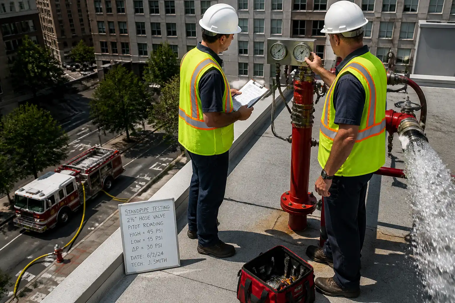

Method Statement: Commissioning of Standpipe Systems (Wet and Dry) – Flow, Pressure, and Fire Brigade Inlet Testing – Method Statement
AI-assisted method statement with matching ITP, PDF download, and Excel export.
More than a static template
Unlike a downloadable Word or PDF template, this method statement is an AI-assisted editable starting point connected directly to a matching Inspection and Test Plan. Every section is structured, project-adaptable, and ready to export.
- AI-assisted drafting — Customize every section with AI for your specific project scope.
- Linked ITP — A matching inspection and test plan is generated alongside the method statement.
- Multiple export formats — Download as a formatted PDF or editable Excel spreadsheet.
- Editable starting point, not a final document — Review, verify, and adjust all content against your project requirements before use.
Static template vs. Quollnet workflow
| Feature | Static template | Quollnet |
|---|---|---|
| Project-specific content | Manual fill-in required | AI-assisted customization |
| Linked ITP | Separate document, no link | Matching ITP included |
| Export formats | Usually PDF only | PDF and Excel |
| Structured sections | Free-form layout | 13 standardized sections |
| Saved to your account | Local file only | Cloud-saved, reusable |
| Content accuracy | You verify everything | AI-assisted, you still verify |
| Cost | Often free but time-intensive | Free to customize and download |
What you can customize
When you save this method statement to your account, every section becomes editable. The following 13 sections are included:
- Scope — Defines the activity and its boundaries.
- References — Standards, specifications, and drawings.
- Responsibilities — Roles and accountabilities.
- Resources — Labour, plant, and equipment summary.
- Materials — Materials and compliance requirements.
- Equipment — Tools and equipment details.
- Prerequisites — Hold points and pre-conditions.
- Method sequence — Step-by-step construction sequence.
- Safety controls — HSE risk controls and PPE.
- Environmental controls — Environmental mitigation measures.
- QA/QC — Quality inspection and test requirements.
- ITP — Inspection and Test Plan table (has its own page).
- Attachments — Referenced drawings and documentation.
Why this method statement is used
This method statement is used to define and communicate the approved procedure for carrying out method statement: commissioning of standpipe systems (wet and dry) – flow, pressure, and fire brigade inlet testing on site. It ensures the work is planned in advance, the correct resources and controls are in place, and all personnel understand responsibilities, sequence, quality requirements, and safety controls before work begins. It aligns site execution with the documented scope and acceptance expectations.
Who uses this method statement
This method statement is used by contractors, site supervisors, project engineers, QA/QC engineers, HSE officers, consultants, and client representatives. It serves as a shared reference for planning, execution, supervision, inspection, and approval of the activity on site.
When it is prepared and submitted
The method statement is prepared before the work activity starts and submitted as part of the pre-construction documentation package for review and approval.
Who reviews or approves it
The method statement is usually submitted to the client representative, consultant, resident engineer, or project management consultant for review and approval before the work commences.
Important approval note
This method statement is an AI-assisted editable starting point, not a pre-approved document. Before use on any project, all content must be reviewed and approved by the relevant parties (superintendent, principal contractor, or client representative) in accordance with your contract and project quality plan.
For example: if your specification requires a departure from a referenced standard, that departure must be documented and approved separately — this method statement will not capture that automatically. Always verify against your applicable drawings, specifications, and regulatory requirements.
Method statement content
Scope
Overview
This method statement defines the procedures, responsibilities, HSE controls, QA/QC, and Inspection & Test Plan (ITP) for commissioning of building standpipe systems (wet and dry). Activities include pre-functional checks, flushing, hydrostatic testing, pneumatic supervision testing (where applicable), flow and pressure testing at roof hydrants and hose connection valves, PRV setting/verification, fire brigade inlet (FDC) testing using a pumper or test pump, documentation, and handover.
Systems Covered
- Class I, II, and III standpipe systems (automatic wet, automatic dry, semiautomatic dry, manual wet, and manual dry) [Verify per project design].
- Associated appurtenances: roof hydrants/manifolds, hose connection valves (1-1/2 in. and 2-1/2 in.), pressure-reducing valves (PRVs), isolation valves, check valves, gauges, drains, test headers, and fire department connections (FDCs).
- Interfaces with fire pumps (if present), water supply mains, and fire alarm/supervisory systems.
Objectives
- Demonstrate system integrity (no leakage), operational readiness, and performance compliance.
- Verify minimum residual pressure and required flow at hydraulically remote outlets and roof hydrants.
- Verify FDC delivers required flows/pressures to remote outlets.
Exclusions
- Permanent fire pump acceptance testing beyond integration steps (separate method if required).
- Permanent building water mains disinfection.
- Structural works or modifications.
Key Acceptance Targets [Verify per project specifications and AHJ]
- Hydrostatic test: 200 psi (13.8 bar) or 50 psi (3.4 bar) above maximum system working pressure, whichever is greater, for 2 hours, no leakage (per NFPA 14).
- Flow testing: Achieve required standpipe total flow and residual pressure at topmost outlets: typically 100 psi (6.9 bar) for Class I/III, 65 psi (4.5 bar) for Class II. Total required flow typically 500–1000 gpm depending on number of standpipes/high-rise classification.
- PRVs: Outlet pressure at rated test flow per design, stable within ±5 psi [Verify per design and NFPA 14].
- Dry standpipe supervision (if used): Stable air/nitrogen supervision pressure over test duration within acceptable drop limits [Verify per project HSE plan and NFPA guidance].
References
| Document Type | Reference / Number | Revision | Notes |
|---|---|---|---|
| Standard | NFPA 14 | Latest adopted by AHJ | Primary acceptance test criteria source; verify edition with AHJ. |
| Standard | NFPA 25 | Latest | Post-acceptance periodic testing guidance. |
| Standard | NFPA 20 | Latest | For coordination with fire pump performance tests (if applicable). |
| Standard | NFPA 1962 | Latest | For hose testing apparatus and nozzles during flow test. |
| Standard | ISO/IEC 17025 | Latest | Calibrations for gauges and flowmeters to be traceable. |
| Contract Docs | Latest approved | Governs project-specific values and acceptance ranges. | |
| Code | AHJ | Current | Hold points and forms per AHJ. |
| Regulation | [Verify per local law] | Current | Permits and safety controls as required. |
Responsibilities
| Role | Responsibility | Name / Party |
|---|---|---|
| PM | Contractor | Contractor |
| Cx Manager | Contractor | Contractor |
| FPE | Contractor | Contractor |
| Supervisor | Contractor | Contractor |
| QA/QC | Contractor | Contractor |
| HSE | Contractor | Contractor |
| Engineer | Consultant | Consultant |
| AHJ | AHJ | Authority |
Resources
| Resource Type | Description | Quantity | Remarks |
|---|---|---|---|
| Manpower | Operate valves, gauges, and test equipment | 4–8 [Verify per site size] | |
| Manpower | Operate fire pump or fire brigade pumper | 1–2 | |
| Manpower | Roof edge management near roof hydrant | As needed |
Materials
| Material | Specification / Grade | Quantity | Remarks |
|---|---|---|---|
| Rubber-lined fire hose | NFPA 1962 compliant | As required | |
| Brass/Stainless | Thread per AHJ | Set per outlet | |
| PTFE tape / pipe dope | Potable-water rated | As needed | |
| Plastic/SS | Per project/AHJ | Complete set | |
| PVC hose/Geotextile | Local environmental standard | As required |
Equipment
| Equipment | Capacity / Type | Quantity | Inspection Required |
|---|---|---|---|
| Pressure gauge | 0–300 psi (0–21 bar) | Min. 4 | |
| Pitot tube + gauge | Up to 1000 gpm | 2 sets | |
| Ultrasonic flowmeter | Appropriate pipe size | 1 | |
| Pump/pumper | Up to 1000 gpm @ 150–250 psi [Verify] | 1 | |
| UHF/VHF radios | 1 per team member | ||
| EN/ANSI certified PPE | As required | ||
| 3 in. layflat hoses | Suitable for 500–1000 gpm | As required |
Prerequisites
- Approved IFC drawings, hydraulic calculations, PRV schedules, and latest AHJ-approved method statement/ITP.
- All piping installed, supported, painted/identified, valves labeled, caps/covers fitted; roof hydrants and hose valves installed with gaskets; drains accessible.
- Fire alarm/supervisory interfaces connected for valve tamper and low-pressure (if applicable) and commissioned to receive signals.
- Water supply available with adequate volume/pressure for flushing and flow tests; drainage plan confirmed with calculated discharge routes and capacities.
- Calibrated gauges/flowmeters within 6 months of test date or per project requirement [Verify per project specifications].
- Permits/notifications: Pressure test permit, hot works NA, working at height permit (roof), traffic management for pumper location, environmental discharge approval [Verify per project HSE plan and local regulations].
- Risk Assessment and Method Statement (RAMS) briefed; toolbox talk conducted; emergency shutdown and spill kits available.
- Coordination with AHJ/Fire Brigade for witnessing schedule and pumper availability (if used).
Method Sequence
| Step | Activity | Description | Responsibility | Inspection / Hold Point |
|---|---|---|---|---|
| 1 | Pre-start coordination & permits | Confirm schedule, permits, AHJ/Consultant attendance, isolation plan, drainage plan, and communication channels. | PM/Supervisor | Document check |
| 2 | Visual inspection & pre-functional checks | Verify supports, hangers, valve orientation, gauges, caps, PRV model/sizes, signage, and accessibility. Confirm isolation valves open (except where required closed for test). | QA/QC, FPE | Walkdown |
| 3 | Underground/main flushing (if applicable) | Flush upstream mains before standpipe connection as per NFPA guidance to achieve 10 ft/s velocity until water runs clear. | Supervisor | Witness turbidity |
| 4 | Standpipe flushing (wet systems) | Flush each riser from the most remote roof hydrant/hose valve using diffuser to remove debris prior to pressure testing. | Supervisor | Witness |
| 5 | Hydrostatic test setup | Isolate system as needed. Fit calibrated gauge at lowest point and highest remote point if feasible. Fill slowly; bleed air at high points. | FPE/Technicians | Witness |
| 6 | Hydrostatic test (wet and dry standpipe piping) | Pressurize to 200 psi or 50 psi above max working pressure (whichever greater) for 2 hours. Monitor joints, valves, FDC piping included. | QA/QC | Hold point (Engineer/AHJ) |
| 7 | Dry system supervision (if applicable) | For dry standpipes with air/nitrogen supervision: charge to specified pressure (typ. 15–40 psi) and monitor for 24 h. | QA/QC | Witness |
| 8 | Valve supervisory/tamper testing | Exercise and prove signals for control valves and low air (if any) to FACP; restore normal. | Commissioning Manager | Witness (Engineer) |
| 9 | PRV pre-set and bench check | Set PRVs per design using manufacturer tools. Pre-check at no-flow to confirm baseline seat tightness. | FPE/Technicians | Witness (Engineer) |
| 10 | Flow test setup | Position discharge hoses/diffusers to safe drains. Place pitot at designated outlets. Establish communication between pump room, FDC, and roof. | Supervisor | Witness |
| 11 | Wet standpipe flow/pressure test (roof and remote outlets) | Using building pump or water main, flow required gpm at hydraulically remote outlets (e.g., 250 gpm per 2-1/2 in. outlet) to achieve total required flow (typically 500–1000 gpm). Measure static and residual pressures at outlets and base-of-riser. | QA/QC/FPE | Hold point (Engineer/AHJ) |
| 12 | PRV performance verification under flow | At each PRV-controlled outlet, measure outlet pressure at design test flow (typ. 250 gpm for 2-1/2 in., 100 gpm for 1-1/2 in.). Fine-tune and lock if needed. | FPE | Witness (Engineer) |
| 13 | Dry standpipe flow test via FDC | Connect pumper to FDC; charge system and flow at remote roof/hose outlets to required total flow while measuring residual pressure. | QA/QC/AHJ | Hold point (AHJ) |
| 14 | FDC integrity and reverse flow check | Verify FDC signage, caps, check valve tightness, and no backflow to public main. Test ball drip drains for operation. | QA/QC | Witness (Engineer) |
| 15 | Draining and restoration | Close outlets; depressurize safely; drain at designated points. Remove temporary gear; restore valves to normal; replace caps and seals; update valve status board. | Supervisor | Witness |
| 16 | Documentation and handover | Compile test certificates, calibration, PRV tags, redlines, and as-built inputs. Obtain Consultant/AHJ sign-off. | QA/QC/PM | Hold point (Engineer/AHJ) |
Health, Safety, and Environment – Safety Controls
Key Hazards and Controls
- Hazard: High-pressure water jet/hose failure during flow tests
- Likely consequence: Lacerations, struck-by injuries, loss of control causing property damage
- Engineering/procedural control: Use hoses and diffusers rated ≥300 psi WP; tether/anchor hose ends; use gradual valve opening; maintain exclusion zones (3 m radius) around outlets; secure couplings; pressure ramp-up protocol
- Required PPE: Helmet with face shield or goggles, gloves (cut-resistant + wet grip), safety boots, hearing protection
- Collective measures: Barricades and signage; spotters at discharge points; remote handling tools for valves where possible
-
Inspection/permit/supervision: Pre-use hose and coupling inspection; calibrated gauges confirmed; Supervisor and QA/QC presence; PTW for pressure testing
-
Hazard: Falls from height at roof hydrants/outlets near edges
- Likely consequence: Serious injury or fatality
- Engineering/procedural control: Establish setback line ≥2 m from roof edge; install temporary guardrails; use fall restraint where guardrails not feasible; pre-plan hose routing away from edges
- Required PPE: Full body harness with restraint lanyard where required
- Collective measures: Roof access control; anchor points certified; rescue plan available
-
Inspection/permit/supervision: Working at Height permit; daily inspection of anchors; HSE Officer to supervise
-
Hazard: Slips, trips, and falls due to wet floors and hoses
- Likely consequence: Sprains, fractures
- Engineering/procedural control: Hose bridging ramps across walkways; anti-slip mats; continuous water management; housekeeping during and after tests
- Required PPE: Non-slip safety boots
- Collective measures: Route hoses along walls; caution signage; keep escape routes clear
-
Inspection/permit/supervision: Supervisor walkdowns every hour during testing
-
Hazard: Pump/pumper noise and vibration
- Likely consequence: Hearing damage, distraction
- Engineering/procedural control: Position pump away from occupied areas; limit duration; maintain pump mounts
- Required PPE: Hearing protection (ear defenders)
- Collective measures: Noise monitoring if >85 dBA
-
Inspection/permit/supervision: Noise assessment; compliance with local limits [Verify per local regulations]
-
Hazard: Traffic interface at pumper/FDC location
- Likely consequence: Vehicle collision with hoses/equipment/personnel
- Engineering/procedural control: Traffic diversion plan; cones, barriers, hose ramps; high-visibility apparel; night lighting
- Required PPE: Hi-vis vest, helmet
- Collective measures: Banksman for vehicle movements
-
Inspection/permit/supervision: Approved traffic management plan; coordination with facility operations
-
Hazard: Stored energy in pneumatic supervision (dry systems)
- Likely consequence: Sudden release causing impact injuries
- Engineering/procedural control: Restrict access to charged areas; pressure relief valves; slow depressurization procedures; clearly marked gauges
- Required PPE: Eye/face protection, gloves
- Collective measures: Barriers and lockable doors
-
Inspection/permit/supervision: PTW; Supervisor to control pressure adjustments; [Verify per project HSE plan]
-
Hazard: Uncontrolled water discharge/flooding
- Likely consequence: Water damage to finishes, electrical hazards, structural ponding
- Engineering/procedural control: Pre-approved drainage routes; test by stages; monitor flow rates vs. drain capacity; protect electrical rooms; bunds around sensitive areas
- Required PPE: Dielectric boots where near electrical; gloves
- Collective measures: Water shutoff points identified; emergency wet-vac pumps ready
-
Inspection/permit/supervision: Drainage capacity check signed off; standby team assigned
-
Hazard: Manual handling of hoses and equipment
- Likely consequence: Strains and musculoskeletal injury
- Engineering/procedural control: Team lifting; use hose reels and dollies; limit single lift to <25 kg [Verify]
- Required PPE: Gloves, back support if specified
- Collective measures: Manual handling training
- Inspection/permit/supervision: Supervisor oversight
Note: Apply additional requirements from project HSE plan and local regulations. Conduct dynamic risk assessment during testing and stop work if conditions change.
Environmental Controls
- Water discharge management: Estimate total flow volume (e.g., 500–1000 gpm for 10–30 min per riser) and confirm receiving drains can accept volume without surcharge. Use layflat hoses to direct water to floor drains or exterior storm drains.
- Sediment and discoloration: First flush may contain rust/scale; deploy silt socks and sediment traps; avoid discharge to landscaped or sensitive areas.
- Chlorine/potable water: If connected to potable mains, avoid discharge to waterways without dechlorination where required [Verify per local regulations].
- Pollution prevention: Keep discharges away from oil separators or sanitary unless authorized. Use spill berms to protect electrical rooms and lifts.
- Noise and hours: Schedule high-flow/pumper tests within permitted hours; apply noise barriers if adjacent to occupied areas.
- Waste: Collect damaged gaskets, tape, and packaging for proper disposal; no materials to enter drains.
- Records: Maintain environmental log with volumes, discharge locations, and any incidents. Obtain approvals from facilities management/AHJ where required.
QA/QC
- Calibrations: All pressure gauges, pitot gauges, and flowmeters to have valid ISO/IEC 17025 traceable calibration certificates (within 6 months unless specified otherwise). Record serial numbers on test sheets.
- Test frequency and coverage: 100% of standpipes, 100% of hose valve outlets and PRVs to be functionally verified. At minimum, flow from topmost outlets per NFPA and design; additionally sample intermediate floors if directed by Consultant/AHJ.
- Measurement uncertainty: Note gauge accuracy class and correct for elevation head differences when comparing base-of-riser and outlet readings.
- Data capture: Record static, residual, and flow values; pump discharge pressure; valve positions; ambient temperature; start/stop times; personnel; instrument IDs. Take photos/videos of gauge faces during peak flow.
- Acceptance criteria: As per NFPA 14, project design, and AHJ directives. Any deviations trigger NCR and corrective action plan.
- PRV settings: Document final settings, lockout devices, and affix durable tags with setpoint, date, and technician initials.
- As-builts: Redline drawings with any changes to valve numbers, outlet IDs, and FDC routing; submit CAD/BIM updates per contract.
- Witnessing: Identify hold/witness points in ITP; ensure Consultant and AHJ sign attendance sheets.
- Handover: Compile commissioning dossier including method, ITP, permits, calibration certs, test sheets, photos, acceptance letters, and O&M excerpts on PRV maintenance.
Attachments
- Sample forms: Hydrostatic Test Certificate; Flow Test Data Sheet (per outlet); PRV Setting & Verification Sheet; FDC Checklist; Calibration Register; Witness/Acceptance Sign-off.
- Sketches: Test configuration diagrams for wet and dry standpipes showing outlet selection, gauge locations, and discharge routing.
- Risk Assessment and Toolbox Talk template specific to high-flow testing and roof work.
- Manufacturer O&M extracts for PRVs and hose valves.
- As-built mark-up sheets for valve/outlet numbering and PRV setpoints.
This content is a read-only public reference. Download or customize to get an editable version.
ITP preview
The first inspection activities from the linked ITP for Method Statement: Commissioning of Standpipe Systems (Wet and Dry) – Flow, Pressure, and Fire Brigade Inlet Testing:
| Activity | Inspection / Test | Acceptance Criteria | Responsibility | Record |
|---|---|---|---|---|
| Document and permit readiness | Check approvals, calibration certificates, permits | All documents current/approved; instruments in calibration | Contractor (C) review; Engineer (E) witness | Pre-commissioning checklist; calibration certs |
| Pre-functional visual inspection | Walkdown against IFC drawings | Correct installation; accessibility; identification; no visible defects | C perform; E witness | Pre-functional inspection record with photos |
| Underground/main flushing (if applicable) | Flow until clear; record turbidity/clarity | Clean discharge; volume and duration logged [Verify per spec] | C perform; E witness | Flushing log and photos |
Showing 3 of 12 inspection activities. View full ITP →
Related Inspection and Test Plan
An Inspection and Test Plan (ITP) is available for Method Statement: Commissioning of Standpipe Systems (Wet and Dry) – Flow, Pressure, and Fire Brigade Inlet Testing. The ITP defines the inspection activities, acceptance criteria, hold and witness points, responsible parties, and records required to verify the work described in this method statement.
View the Method Statement: Commissioning of Standpipe Systems (Wet and Dry) – Flow, Pressure, and Fire Brigade Inlet Testing ITP →