Method Statement – Fire Alarm Monitoring Interface for Fire Pump and Firefighting Systems – Method Statement
AI-assisted method statement with matching ITP, PDF download, and Excel export.
More than a static template
Unlike a downloadable Word or PDF template, this method statement is an AI-assisted editable starting point connected directly to a matching Inspection and Test Plan. Every section is structured, project-adaptable, and ready to export.
- AI-assisted drafting — Customize every section with AI for your specific project scope.
- Linked ITP — A matching inspection and test plan is generated alongside the method statement.
- Multiple export formats — Download as a formatted PDF or editable Excel spreadsheet.
- Editable starting point, not a final document — Review, verify, and adjust all content against your project requirements before use.
Static template vs. Quollnet workflow
| Feature | Static template | Quollnet |
|---|---|---|
| Project-specific content | Manual fill-in required | AI-assisted customization |
| Linked ITP | Separate document, no link | Matching ITP included |
| Export formats | Usually PDF only | PDF and Excel |
| Structured sections | Free-form layout | 13 standardized sections |
| Saved to your account | Local file only | Cloud-saved, reusable |
| Content accuracy | You verify everything | AI-assisted, you still verify |
| Cost | Often free but time-intensive | Free to customize and download |
What you can customize
When you save this method statement to your account, every section becomes editable. The following 13 sections are included:
- Scope — Defines the activity and its boundaries.
- References — Standards, specifications, and drawings.
- Responsibilities — Roles and accountabilities.
- Resources — Labour, plant, and equipment summary.
- Materials — Materials and compliance requirements.
- Equipment — Tools and equipment details.
- Prerequisites — Hold points and pre-conditions.
- Method sequence — Step-by-step construction sequence.
- Safety controls — HSE risk controls and PPE.
- Environmental controls — Environmental mitigation measures.
- QA/QC — Quality inspection and test requirements.
- ITP — Inspection and Test Plan table (has its own page).
- Attachments — Referenced drawings and documentation.
Why this method statement is used
This method statement is used to define and communicate the approved procedure for carrying out method statement – fire alarm monitoring interface for fire pump and firefighting systems on site. It ensures the work is planned in advance, the correct resources and controls are in place, and all personnel understand responsibilities, sequence, quality requirements, and safety controls before work begins. It aligns site execution with the documented scope and acceptance expectations.
Who uses this method statement
This method statement is used by contractors, site supervisors, project engineers, QA/QC engineers, HSE officers, consultants, and client representatives. It serves as a shared reference for planning, execution, supervision, inspection, and approval of the activity on site.
When it is prepared and submitted
The method statement is prepared before the work activity starts and submitted as part of the pre-construction documentation package for review and approval.
Who reviews or approves it
The method statement is usually submitted to the client representative, consultant, resident engineer, or project management consultant for review and approval before the work commences.
Important approval note
This method statement is an AI-assisted editable starting point, not a pre-approved document. Before use on any project, all content must be reviewed and approved by the relevant parties (superintendent, principal contractor, or client representative) in accordance with your contract and project quality plan.
For example: if your specification requires a departure from a referenced standard, that departure must be documented and approved separately — this method statement will not capture that automatically. Always verify against your applicable drawings, specifications, and regulatory requirements.
Method statement content
Scope
Overview
This method statement covers installation, configuration, testing, and documentation of the fire alarm monitoring interface for fire pump and firefighting systems, including:
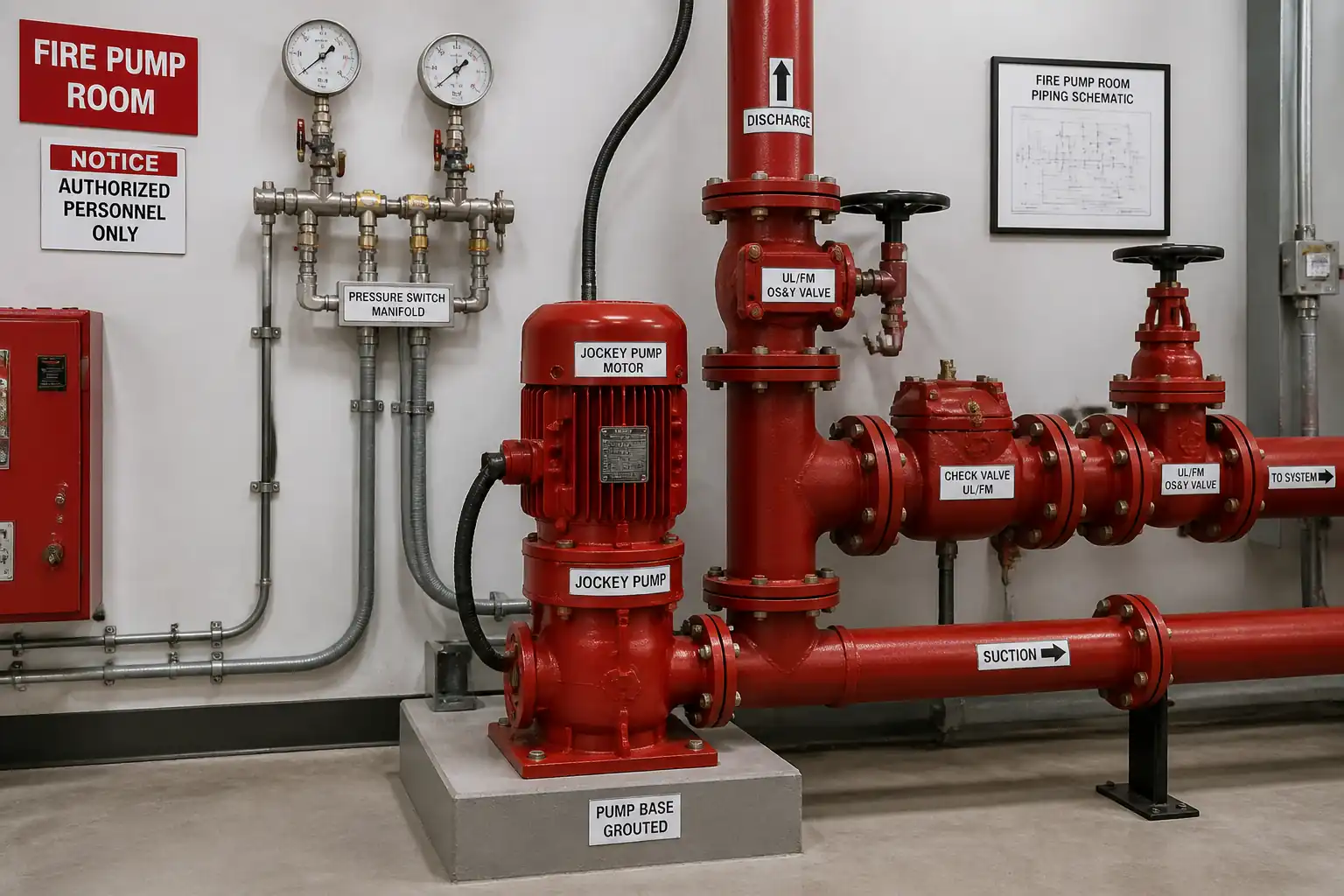
- Monitoring interface between Fire Alarm Control Panel (FACP) and fire pump controllers (electric and diesel), jockey pump controller, and associated firefighting system devices (e.g., pressure switches, flow switches, valve supervisory switches) as defined by the approved Cause & Effect Matrix.
- Supply and installation of addressable monitor modules, isolators, interface relays, backboxes, terminations, labeling, and end-of-line (EOL) supervision.
- Point-to-point verification, programming, functional tests (simulation and live), system integration checks, QA/QC witnessing, preparation of records, and submission for consultant/authority approval.
Deliverables
- Installed and labeled monitoring points for: Pump Run, Pump Controller Trouble/Fail, Phase Failure (electric), Engine Running, Fail to Start, Low Fuel, Battery/Charger Trouble (diesel), Jockey Pump Run/Fail, Low Suction/Low Tank Level (if monitored), and other firefighting status signals [Verify per project specifications].
- Updated Cause & Effect (C&E) logic in FACP; verified event classification (Alarm/Supervisory/Trouble) per NFPA 72 and approved C&E.
- Completed inspection and test records, as-built drawings, point lists, and O&M documentation.
Exclusions
- Any control of fire pumps from the FACP (monitoring only).
- Fire pump performance testing beyond signals required for interface verification (conducted by firefighting vendor under separate method; coordinated here for interface checks).
- BMS integration unless specified in the project scope.
References
| Document Type | Reference / Number | Revision | Notes |
|---|---|---|---|
| Code | NFPA 72 (latest adopted edition) | Signal types, supervision, annunciation, testing. | |
| Code | NFPA 20 (latest adopted edition) | Pump controller status contacts and indications, run test coordination. | |
| Code/Standard | NFPA 70 (NEC) or IEC 60364 / BS 7671 [Project standard to apply] | Circuit segregation, conductor sizing, grounding/earthing. | |
| Standard | BS EN 54-2/-4/-13 (as applicable) | System integrity, compatibility, and monitoring interfaces. | |
| Standard | BS EN 12845 | For interface with sprinkler flow/valve supervisory switches where applicable. | |
| Listing/Standard | UL 864 (FACP), UL 346/508 (controls) or equivalent listing | All interface components to be listed/approved for fire use. | |
| Manual | OEM latest manuals | Follow OEM terminal ratings, relay isolation, and address limits. | |
| Contract Spec | Division 21/26/28 [Verify] | Cable type, color coding, labeling, testing frequencies. |
Responsibilities
| Role | Responsibility | Name / Party |
|---|---|---|
| PM | Lead | Main Contractor |
| Coordinate | Main Contractor | |
| Execute | Specialist | |
| Support | Specialist | |
| Inspect | Main Contractor | |
| HSE | Main Contractor | |
| Commission | Main Contractor/Specialist | |
| Approve | Consultant/Authority |
Resources
| Resource Type | Description | Quantity | Remarks |
|---|---|---|---|
| Manpower | Installation, termination, programming | 2–4 [Verify per project] | |
| Manpower | Cable pulling, containment, power isolation support | 2–3 | |
| Manpower | Integrated testing and C&E verification | 1–2 | |
| Manpower | Permits, site safety monitoring | 1 | |
| Manpower | Inspections and records | 1 |
Materials
| Material | Specification / Grade | Quantity | Remarks |
|---|---|---|---|
| Monitor module | Compatible with FACP; environmental rating per site | As per point list +10% spares | |
| Isolator module | UL/EN54 listed | As design | |
| Relay | UL/CE listed, DIN-rail mount | As required | |
| Resistor | 0.25W min, ±5% | As per circuits + spares | |
| Cable | Compliant with NFPA/BS standards [Verify] | As per drawings +10% | |
| Boxes and accessories | Listed/compatible with modules | As required | |
| Labels | LSZH, UV-resistant | As required |
Equipment
| Equipment | Capacity / Type | Quantity | Inspection Required |
|---|---|---|---|
| Multimeter | 2 | ||
| Megger | 1 | ||
| Laptop | 1 | ||
| Crimpers, screwdrivers | Set | ||
| Ladders/MEWP | As needed | ||
| Locks/tags | Set |
Prerequisites
- Approved shop drawings, schematics, and I/O points list aligned with the Cause & Effect Matrix.
- Approved method statement and ITP; task-specific risk assessment; permits (LOTO, impairment to life safety systems, work at height as applicable) [Verify per project HSE plan and local regulations].
- Confirm fire pump controller OEM provides potential-free contacts for each required signal; verify normal state (NO/NC), contact rating, and terminal identification.
- Confirm segregation, containment routes, and supports are complete and accessible; confirm firestopping strategy for penetrations.
- Calibrated test instruments and OEM programming tools available.
- Confirm that disabling of any active fire protection is covered by an approved impairment plan and temporary fire watch if required.
- Pre-test meeting with firefighting vendor and consultant to align test scripts, roles, and witness points.
- Confirm temporary power and drainage arrangements for pump functional checks (if run testing is included for interface verification).
Method Sequence
| Step | Activity | Description | Responsibility | Inspection / Hold Point |
|---|---|---|---|---|
| 1 | Pre-start coordination | Review approved drawings, C&E matrix, I/O schedule. Walkdown pump room and routes; identify module locations within 1 m of monitored equipment where practicable. | MEP Coordinator / FA Subcontractor | Planning meeting record |
| 2 | Verify contacts and states | With firefighting vendor, confirm each required contact is potential-free and its normal state (NO/NC): Pump Run, Controller Trouble/Fail, Phase Failure, Engine Running, Fail to Start, Low Fuel, Battery/Charger Trouble, Jockey Run/Fail, Low Suction/Low Level, etc. [Verify per project specs]. | FA Subcontractor / Firefighting Vendor | I/O checklist |
| 3 | Permits and isolations | Implement LOTO on relevant control panels where live work is not required. Raise impairment permit for affected alarm zones if necessary. Barricade work area. | HSE / Site Supervisor | Permit to Work, LOTO log |
| 4 | Install containment and boxes | Fix backboxes/JBs near controllers; ensure IP rating; provide gland plates and earth continuity. Maintain segregation from LV power ≥50 mm or solid barrier [Verify per code]. Support spacing ≤1.2 m for conduits/mini-trunking [Verify per project]. | Electricians | In-process QC |
| 5 | Cable pulling | Pull fire-rated cable between modules and FACP loop/ SLC. Respect bend radius ≥8×OD (MICC ≥6×OD). Use draw numbers. Avoid mixing with power in same conduit unless barriered and permitted. | Electricians / FA Technicians | Visual check |
| 6 | Module mounting and labeling | Mount addressable monitor/isolator modules in listed backboxes or cabinets. Provide permanent labels: Panel/Loop/Address/Point descriptor. Provide unique address per loop; observe loop capacity limits [Verify per OEM]. | FA Technicians | QC inspection |
| 7 | Terminations and EOL | Terminate cables to module and to controller dry contacts via interposing relay if needed. Tighten to OEM torque (typ. 0.5–0.8 Nm [Verify]). Install EOL resistor at field device/JB end, not in panel. | FA Technicians | Termination inspection |
| 8 | Continuity and IR testing | With all electronics disconnected, perform continuity and insulation resistance tests on field circuits. Use 250 V DC IR for FA circuits. | QA/QC / FA Technicians | Witness (W) |
| 9 | FACP programming | Add points with exact descriptors and event type (Supervisory/Trouble/Alarm) per approved C&E. Download/backup configuration and print point list. | FA Programmer | Review |
| 10 | Loop integrity check | Reconnect loops, power up FACP. Verify normal status for all new devices. Simulate open/short to confirm supervision. | FA Technicians | W |
| 11 | Point-to-point signal simulation | For each monitored contact, simulate change of state at the field end to confirm correct point, location text, and event type at FACP and any repeater/graphics. | FA Technicians / QA/QC | Hold (H) |
| 12 | Integrated functional checks | Coordinate live run tests of pumps (as required) to verify RUN/FAIL and ancillary status under actual operation. Ensure no control from FACP to pump. Manage drainage and noise controls. | Commissioning Engineer / Firefighting Vendor | W/H (as required) |
| 13 | Graphics/BMS mapping (if in scope) | Verify points and priorities on graphics workstation/BMS with correct descriptors and classes. | FA/BMS Engineer | W |
| 14 | Labeling and as-builts | Affix final engraved labels to panels/JBs; update redlines with cable routes, module addresses. Produce as-built drawings and point list. | FA Subcontractor | QC |
| 15 | Final QA/QC review | Close NCRs/snags; verify documentation completeness; prepare handover dossier. | QA/QC Engineer | Review |
| 16 | Training and turnover | Provide end-user training on alarm classifications, annunciation, and logs. Submit O&M manuals, spares, and warranties. | FA Vendor / Main Contractor | Witness |
Health, Safety and Environment (HSE) – Task-Specific Safety Controls
Major Hazards and Controls
- Hazard: Exposure to live electrical parts at pump controllers (often >400 V).
- Likely consequence: Electric shock, arc flash burns, fatality.
- Engineering/procedural control: LOTO of controllers prior to interface wiring; test for dead; use insulated tools; no energized work unless justified by a permit with additional controls.
- Required PPE: Arc-rated clothing (CAT 2 minimum [Verify]), insulated gloves, face shield, safety glasses, safety footwear.
- Collective measure: Barriers and signage around pump room; restrict access; maintain safe approach distances.
-
Inspection/permit/supervision: Electrical isolation certificate; LOTO log; Supervisor sign-off; periodic HSE audits.
-
Hazard: Fire protection impairment during testing/programming.
- Likely consequence: Reduced life safety protection.
- Engineering/procedural control: Formal impairment plan; temporary detection/watch; notify stakeholders; limit impairment duration; restore promptly.
- Required PPE: Standard site PPE.
- Collective measure: Dedicated fire watch with communication; additional extinguishers available.
-
Inspection/permit/supervision: Impairment permit; client/authority notification as required.
-
Hazard: Working at height on trays and along ceilings.
- Likely consequence: Falls leading to serious injury.
- Engineering/procedural control: Use inspected podium steps/MEWP; maintain three points of contact; no overreaching; tie-off where required.
- Required PPE: Harness and lanyard for MEWP as required, hard hat, gloves, safety footwear.
- Collective measure: Exclusion zone under work area; toe boards on podiums.
-
Inspection/permit/supervision: Pre-use inspection; Working at Height permit; trained operators only.
-
Hazard: Drilling/coring for supports in pump room walls/ceilings.
- Likely consequence: Struck-by, dust inhalation, hit embedded services.
- Engineering/procedural control: Scan for services; use dust extraction and anchors per design; use SDS drills with guards.
- Required PPE: Eye protection, hearing protection, dust mask (P2/P3), gloves.
- Collective measure: Local ventilation; housekeeping to remove dust/debris.
-
Inspection/permit/supervision: Permit to Drill; service scan record.
-
Hazard: Noise during live pump run testing.
- Likely consequence: Hearing damage.
- Engineering/procedural control: Limit test duration; schedule during low-occupancy times; close doors; post warning signage.
- Required PPE: Hearing protection (≥25 dB SNR earmuffs).
- Collective measure: Controlled access during test window.
-
Inspection/permit/supervision: Test plan with time window; noise level spot checks.
-
Hazard: Water discharge/standing water during pump run testing.
- Likely consequence: Slips, electrical hazard if contacting live parts.
- Engineering/procedural control: Route discharge to approved drain or test header; bund sensitive equipment; keep electrics elevated/dry.
- Required PPE: Waterproof boots with slip-resistant soles.
- Collective measure: Squeegees, wet vac on standby; absorbent mats.
-
Inspection/permit/supervision: Pre-test area inspection; housekeeping sign-off.
-
Hazard: Manual handling of cables and equipment in confined spaces.
- Likely consequence: Musculoskeletal injuries.
- Engineering/procedural control: Use team lifts, reels stands, plan routes; keep loads within limits.
- Required PPE: Gloves, safety footwear.
- Collective measure: Clear walkways; staging of materials.
- Inspection/permit/supervision: Toolbox talk; supervisor monitoring.
[Verify per project HSE plan and local regulations]
Environmental Controls
- Cable and packaging waste: Segregate recyclable materials; store in designated bins; dispose through licensed waste contractor.
- Dust from drilling: Use vacuum extraction and wet methods where feasible; prevent spread to adjacent areas with temporary sheeting.
- Noise from pump testing: Limit duration, monitor dB levels, schedule outside sensitive hours; doors closed to contain noise.
- Water from pump run: Route to approved drain; use silt sock if sediment present; prevent contamination; do not discharge oily water.
- Energy use and idling: Switch off equipment when not in use; avoid MEWP idling.
- Spill prevention: Keep spill kits available; refuel diesel pump (if applicable) in designated area with drip trays.
- Records: Keep environmental checklists and waste transfer notes for audit.
Quality Assurance / Quality Control
QA/QC Controls
- Materials: Verify listings (UL/EN54), certificates of conformity, and model numbers against the approved submittals.
- Workmanship: Ferruled, torque-verified terminations; no exposed copper; correct polarity; EOL at field end.
- Identification: Permanent labels on modules, JBs, and cables with panel/loop/address/point.
- Segregation: Maintain minimum separations from power; use barriers where required [Verify per code/spec].
- Testing:
- 100% continuity and IR of new circuits before connection to electronics (IR ≥2 MΩ at 250 V DC [Verify per spec]).
- 100% point-to-point simulation; no cross talk.
- Loop supervision: open/short simulated and annunciated within manufacturer polling cycle [Verify].
- Integrated test: live verification of critical statuses during pump run (where included).
- Documentation: ITP checklists, calibration certificates, signed witness sheets, updated C&E, as-built drawings (PDF + native), O&M manuals, training records.
- Acceptance: Zero Category A defects; remaining minor snags closed prior to handover or with agreed punch list and rectification plan.
Attachments
- Approved shop drawings and schematics (fire alarm and firefighting interfaces)
- Approved Cause & Effect Matrix
- Manufacturer data sheets and installation manuals (FACP, modules, controllers, relays)
- I/O verification sheet with terminal IDs and states (NO/NC)
- Cable schedules and route drawings
- Calibration certificates for test instruments
- IR/continuity test reports
- Point database printout and backup confirmation
- Point-to-point and integrated test sheets with witness signatures
- As-built drawings (PDF + native), label schedules
- O&M manuals, training attendance records
- Permits and HSE records (LOTO, impairment, work at height, drilling)
This content is a read-only public reference. Download or customize to get an editable version.
ITP preview
The first inspection activities from the linked ITP for Method Statement – Fire Alarm Monitoring Interface for Fire Pump and Firefighting Systems:
| Activity | Inspection / Test | Acceptance Criteria | Responsibility | Record |
|---|---|---|---|---|
| Material receipt inspection | Materials per approved submittal; UL/EN54 listed; no damage; certificates available. | QA/QC Engineer / FA Subcontractor | Material inspection report, COC, delivery notes | |
| Shop drawings and I/O list approval | Approved drawings, point schedule, and C&E matrix issued IFC. | Consultant / Main Contractor | Approved drawings, C&E | |
| Containment and box installation inspection | Supports, IP rating, segregation, bonding compliant. | QA/QC Engineer | Containment/JB inspection checklist, photos |
Showing 3 of 11 inspection activities. View full ITP →
Related Inspection and Test Plan
An Inspection and Test Plan (ITP) is available for Method Statement – Fire Alarm Monitoring Interface for Fire Pump and Firefighting Systems. The ITP defines the inspection activities, acceptance criteria, hold and witness points, responsible parties, and records required to verify the work described in this method statement.
View the Method Statement – Fire Alarm Monitoring Interface for Fire Pump and Firefighting Systems ITP →Frequently asked questions
Continue with related Quollnet resources connected to this method statement.