Hydraulic System Inspection & Leak Control for Excavators + Attachments
Definition: Hydraulic System Inspection & Leak Control (All Excavators + Attachments) is a field-ready checklist for technicians to validate hoses, seals, pumps, and attachments, prevent leaks, and document safe, efficient operation.
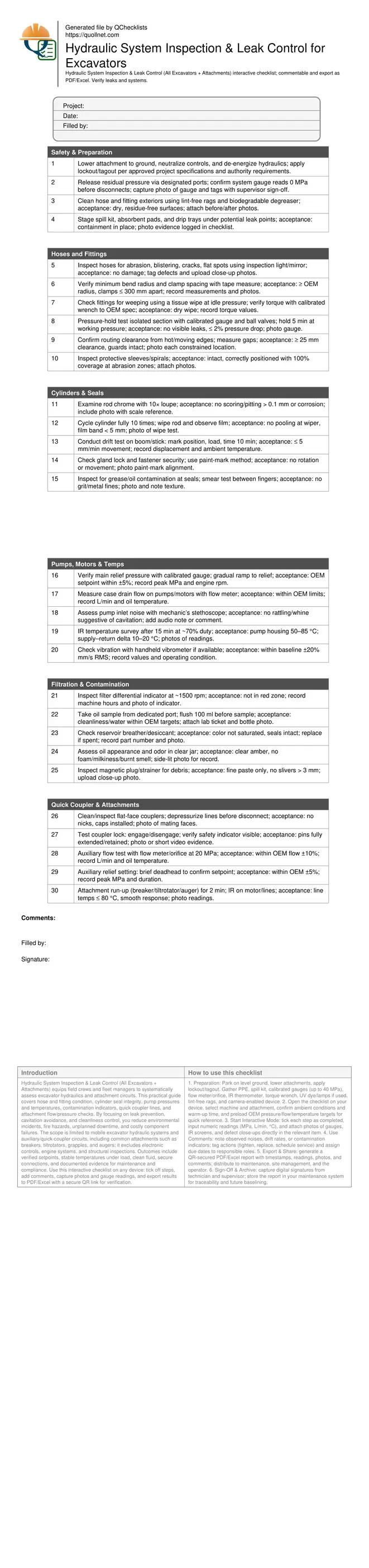
- Inspect hoses, fittings, cylinders, pumps, temps, contamination, and couplers.
- Prevent downtime, spills, and fire risks; extend component and oil life.
- Use gauges, flow meters, IR thermometers; record readings with photos.
- Interactive, commentable checklist with photo capture, export, and QR code verification.
Hydraulic System Inspection & Leak Control (All Excavators + Attachments) equips field crews and fleet managers to systematically assess excavator hydraulics and attachment circuits. This practical guide covers hose and fitting condition, cylinder seal integrity, pump pressures and temperatures, contamination indicators, quick coupler lines, and attachment flow/pressure checks. By focusing on leak prevention, cavitation avoidance, and cleanliness control, you reduce environmental incidents, fire hazards, unplanned downtime, and costly component failures. The scope is limited to mobile excavator hydraulic systems and auxiliary/quick-coupler circuits, including common attachments such as breakers, tiltrotators, grapples, and augers; it excludes electronic controls, engine systems, and structural inspections. Outcomes include verified setpoints, stable temperatures under load, clean fluid, secure connections, and documented evidence for maintenance and compliance. Use this interactive checklist on any device: tick off steps, add comments, capture photos and gauge readings, and export results to PDF/Excel with a secure QR link for verification.
- Comprehensive hydraulic inspection workflow tailored to excavators and attachments ensures hoses, fittings, cylinders, pumps, and auxiliary circuits are verified under realistic duty cycles. Capture objective evidence with calibrated gauges, flow meters, and IR thermography to validate pressures, temperatures, and component health before returning equipment to service.
- Leak control focuses on early detection of weeping joints, seal wear, abrasion, and contamination routes. Practical methods—tissue wipe tests, drift checks, and breather and filter condition reviews—help prevent progressive failures, environmental releases, and fire risks while improving machine responsiveness and operator confidence.
- Interactive online checklist with tick, comment, and export features secured by QR code.
- Results-driven records support condition-based maintenance and audits. Export photo-backed findings with readings and sign-offs, align relief settings with OEM limits, benchmark normal temperature deltas, and document cleanliness targets to extend oil life, protect pumps and motors, and minimize unplanned downtime across the fleet.
Safety & Preparation
Hoses and Fittings
Cylinders & Seals
Pumps, Motors & Temps
Filtration & Contamination
Quick Coupler & Attachments
Finding Leaks Early: Practical Detection Methods That Work On-Site
Most hydraulic failures begin as small weeps that attract dust and hide damage. Start with a clean system, then scan fittings, hose crimps, and cylinder glands under idle and working pressure. Tissue or cardboard wipe tests reveal weeping without injury risk—never use bare hands on pressurized lines. Talc powder lightly applied around suspect areas helps highlight fresh fluid paths after cycling functions. For elusive leaks, add UV dye per fluid compatibility and inspect with a UV lamp in shaded conditions. Confirm suspected points with a short pressure-hold test on isolated sections using ball valves and a calibrated gauge. Always document with close-up photos, note the operating state, and tag components for planned replacement. Early action prevents hose bursts, fire risk from atomized spray, and contamination of soil or waterways. Record evidence consistently so your team can compare conditions between shifts and schedule repairs ahead of failure.
- Clean first; dirt hides weeping and abrasion.
- Use tissue or cardboard, never hands, for leak checks.
- Apply talc or UV dye to trace tiny leaks.
- Confirm with short pressure-hold tests.
- Photograph defects with operating state noted.
Temperatures, Pressures, and Drift: Acceptance Cues You Can Trust
Temperatures and pressures provide fast insight into pump health, relief settings, and flow losses. Warm the system under a steady workload before readings to avoid cold-bias results. Use an IR thermometer at consistent angles and emissivity; place matte tape on shiny surfaces to improve accuracy. Healthy pumps typically run 50–85 °C with a 10–20 °C delta between supply and return during moderate duty. Abnormal whine near the inlet hints at cavitation—check suction restrictions and oil level. Relief pressures should match OEM specifications within narrow tolerances; record engine rpm during tests. Cylinder drift measurements quantify seal bypass or valve leakage; measure displacement over time with load applied and log ambient temperature. Re-check after addressing air entrainment, which can skew results. Store all readings with photos of gauges and IR screens to build reliable baselines for each machine and attachment.
- Warm up before pressure and temperature checks.
- Use matte tape to improve IR accuracy.
- Expect 10–20 °C supply–return delta.
- Log engine rpm and ambient temperature.
- Measure cylinder drift under load.
Contamination Control: Cleanliness, Sampling, and Coupler Discipline
Particle and moisture control is central to hydraulic reliability. Inspect filter differential indicators and replace elements before bypass. Keep breathers effective; desiccant changes color as it saturates with moisture. When sampling oil, flush the port first and collect in clean, sealed bottles to avoid skewed results. Evaluate color, odor, foam, and lab particle counts against OEM targets. Magnetic plugs and strainers should capture fine paste, not sharp slivers—large fragments indicate active wear. Flat-face couplers must be cleaned and depressurized before connecting attachments; damaged faces rapidly introduce debris and cause leaks. During flow tests, maintain oil at typical working temperature to obtain meaningful results. Document lab reports, part numbers, and photos to support root-cause analysis and warranty claims. Good cleanliness practices extend pump and valve life, reduce drift complaints, and stabilize attachment performance across variable job demands.
- Replace filters before bypass is indicated.
- Flush sampling ports; use clean bottles.
- Check desiccant breathers and seals.
- Clean and depressurize couplers before use.
- Record lab results and part numbers.
How to Use This Interactive Checklist
- Preparation: Park on level ground, lower attachments, apply lockout/tagout. Gather PPE, spill kit, calibrated gauges (up to 40 MPa), flow meter/orifice, IR thermometer, torque wrench, UV dye/lamps if used, lint-free rags, and camera-enabled device.
- Open the checklist on your device, select machine and attachment, confirm ambient conditions and warm-up time, and preload OEM pressure/flow/temperature targets for quick reference.
- Start Interactive Mode: tick each step as completed, input numeric readings (MPa, L/min, °C), and attach photos of gauges, IR screens, and defect close-ups directly in the relevant item.
- Use Comments: note observed noises, drift rates, or contamination indicators; tag actions (tighten, replace, schedule service) and assign due dates to responsible roles.
- Export & Share: generate a QR-secured PDF/Excel report with timestamps, readings, photos, and comments; distribute to maintenance, site management, and the operator.
- Sign-Off & Archive: capture digital signatures from technician and supervisor; store the report in your maintenance system for traceability and future baselining.
Call to Action
- Start Checklist Tick off tasks, leave comments on items or the whole form, and export your completed report to PDF or Excel—with a built-in QR code for authenticity.
- Download Excel - Hydraulic System Inspection & Leak Control
- Download PDF - Hydraulic System Inspection & Leak Control
- View Image - Hydraulic System Inspection & Leak Control
Cite & Embed
“Hydraulic System Inspection & Leak Control by Quollnet”
with a link to
this source page.

FAQ
Question: How often should I perform hydraulic system inspection and leak control on excavators?
Question: What should I do if I see minor weeping at a fitting or cylinder seal?
Question: How can I differentiate cavitation from normal pump noise in the field?
Question: What is the safest way to depressurize quick coupler lines before changing attachments?
Related Articles
Broader reading and guidance connected to this checklist topic.


Major Construction Defects That Needs Immediate Attention
Related Checklists
Keep the workflow moving with nearby templates chosen from similar checklist content.