
Method Statement: Fire Alarm Detection and Notification Devices Installation – Method Statement
AI-assisted method statement with matching ITP, PDF download, and Excel export.
More than a static template
Unlike a downloadable Word or PDF template, this method statement is an AI-assisted editable starting point connected directly to a matching Inspection and Test Plan. Every section is structured, project-adaptable, and ready to export.
- AI-assisted drafting — Customize every section with AI for your specific project scope.
- Linked ITP — A matching inspection and test plan is generated alongside the method statement.
- Multiple export formats — Download as a formatted PDF or editable Excel spreadsheet.
- Editable starting point, not a final document — Review, verify, and adjust all content against your project requirements before use.
Static template vs. Quollnet workflow
| Feature | Static template | Quollnet |
|---|---|---|
| Project-specific content | Manual fill-in required | AI-assisted customization |
| Linked ITP | Separate document, no link | Matching ITP included |
| Export formats | Usually PDF only | PDF and Excel |
| Structured sections | Free-form layout | 13 standardized sections |
| Saved to your account | Local file only | Cloud-saved, reusable |
| Content accuracy | You verify everything | AI-assisted, you still verify |
| Cost | Often free but time-intensive | Free to customize and download |
What you can customize
When you save this method statement to your account, every section becomes editable. The following 13 sections are included:
- Scope — Defines the activity and its boundaries.
- References — Standards, specifications, and drawings.
- Responsibilities — Roles and accountabilities.
- Resources — Labour, plant, and equipment summary.
- Materials — Materials and compliance requirements.
- Equipment — Tools and equipment details.
- Prerequisites — Hold points and pre-conditions.
- Method sequence — Step-by-step construction sequence.
- Safety controls — HSE risk controls and PPE.
- Environmental controls — Environmental mitigation measures.
- QA/QC — Quality inspection and test requirements.
- ITP — Inspection and Test Plan table (has its own page).
- Attachments — Referenced drawings and documentation.
Why this method statement is used
This method statement is used to define and communicate the approved procedure for carrying out method statement: fire alarm detection and notification devices installation on site. It ensures the work is planned in advance, the correct resources and controls are in place, and all personnel understand responsibilities, sequence, quality requirements, and safety controls before work begins. It aligns site execution with the documented scope and acceptance expectations.
Who uses this method statement
This method statement is used by contractors, site supervisors, project engineers, QA/QC engineers, HSE officers, consultants, and client representatives. It serves as a shared reference for planning, execution, supervision, inspection, and approval of the activity on site.
When it is prepared and submitted
The method statement is prepared before the work activity starts and submitted as part of the pre-construction documentation package for review and approval.
Who reviews or approves it
The method statement is usually submitted to the client representative, consultant, resident engineer, or project management consultant for review and approval before the work commences.
Important approval note
This method statement is an AI-assisted editable starting point, not a pre-approved document. Before use on any project, all content must be reviewed and approved by the relevant parties (superintendent, principal contractor, or client representative) in accordance with your contract and project quality plan.
For example: if your specification requires a departure from a referenced standard, that departure must be documented and approved separately — this method statement will not capture that automatically. Always verify against your applicable drawings, specifications, and regulatory requirements.
Method statement content
Scope
Description
This method statement covers procurement verification, installation, wiring, addressing, protection, QA/QC inspections, testing, and documentation for fire alarm devices including:
- Addressable or conventional point smoke detectors, heat detectors, manual call points (MCPs), audible sounders, visual beacons (VADs), interfaces/isolation bases, and ancillary modules.
- Associated first-fix boxes, containment, fire-resistant cables, terminations, labeling, fire-stopping, and integration to Fire Alarm Control Panel (FACP) and power supplies.
- Pre-commissioning tests, functional verification, compliance checks, punch listing, and handover records.
Exclusions
- Detailed FACP programming/commissioning and authority witnessed final acceptance (performed by approved commissioning specialist and AHJ).
- Civil/architectural making good beyond fire-stopping and device escutcheon finishes.
Objectives
- Install per approved shop drawings and cause & effect matrix.
- Achieve compliance with relevant codes and project specifications.
- Deliver complete as-built documentation and test records for commissioning readiness.
References
| Document Type | Reference / Number | Revision | Notes |
|---|---|---|---|
| Standard | NFPA 72 | ||
| Standard | BS 5839-1 | ||
| Standard | EN 54 / ISO 7240 | ||
| Standard | IEC 60364 | ||
| Standard | BS 7671 | ||
| Standard | EN 1366-3 / UL 1479 | ||
| Manual | Per approved submittal | ||
| Contract Docs | As issued for construction |
Responsibilities
| Role | Responsibility | Name / Party |
|---|---|---|
| Management | PM | Contractor |
| Supervision | CM/ES | Contractor |
| QA/QC | QA/QC | Contractor |
| HSE | HSEO | Contractor |
| Commissioning | CxE | Specialist |
| Engineer | Engineer | Employer/Engineer |
| Authority | AHJ | Regulator |
Resources
| Resource Type | Description | Quantity | Remarks |
|---|---|---|---|
| Manpower | ELV/fire alarm experienced, trained on OEM system. | As per manpower histogram | |
| Manpower | Loop tester operation, device addressing, functional testing. | As required | |
| Manpower | Permit issuer, spotter for work at height, first aider. | Per risk assessment |
Materials
| Material | Specification / Grade | Quantity | Remarks |
|---|---|---|---|
| FACP/PSU/Batteries | |||
| Detectors | |||
| Sounders/VADs | |||
| MCPs | |||
| FR cables | [Verify size per project] | ||
| Containment | |||
| Accessories |
Equipment
| Equipment | Capacity / Type | Quantity | Inspection Required |
|---|---|---|---|
| Sets as required | Yes | ||
| As needed | Yes | ||
| Yes | |||
| Yes |
Prerequisites
Approvals and Documentation
- Approved shop drawings, device layout, loop schematics, cause & effect matrix, and device schedule.
- Approved material submittals for all components and fire-stopping systems.
- Method statement and ITP approved by Engineer.
- Risk Assessment/Method Statement (RAMS) briefed via toolbox talks; permits obtained [Verify per project HSE plan and local regulations].
Site Readiness
- Work areas released; ceilings/grids accessible; walls finished to permit accurate MCP mounting heights.
- Coordination completed with other trades (HVAC diffusers, lighting, sprinklers) to avoid detector placement conflicts.
- Power supplies for FACP and PSUs installed and safe to energize (isolated/locked out during ELV works as required).
Tools and Calibration
- Test instruments calibrated; function check logs available.
- OEM programming tools/software/licenses available.
Competency
- Electricians and technicians trained on the specific OEM system and this method.
Material Handling
- Devices stored in clean, dry area; detectors kept sealed in packaging until final fix to avoid contamination.
Method Sequence
| Step | Activity | Description | Responsibility | Inspection / Hold Point |
|---|---|---|---|---|
| 1 | Material receipt and verification | Check deliveries against approved submittals: model numbers, certifications (EN 54/UL/NFPA), accessories. Inspect for damage. | QA/QC + Storekeeper | WIR |
| 2 | Setting out and mounting heights | Mark device locations as per drawings. Typical heights: MCP centerline 1.4 m ±0.2 m AFFL; wall-mounted detectors 100–300 mm below ceiling; ceiling-mounted per OEM; sounders/VAD per coverage data [Verify per project specs]. | Electrical Supervisor | IR |
| 3 | First fix: containment and back boxes | Install metallic conduits/trunking and back boxes. Use non-combustible fixings at required spacings; maintain clearances from EMI sources. Provide draw wires. | Electricians | IR |
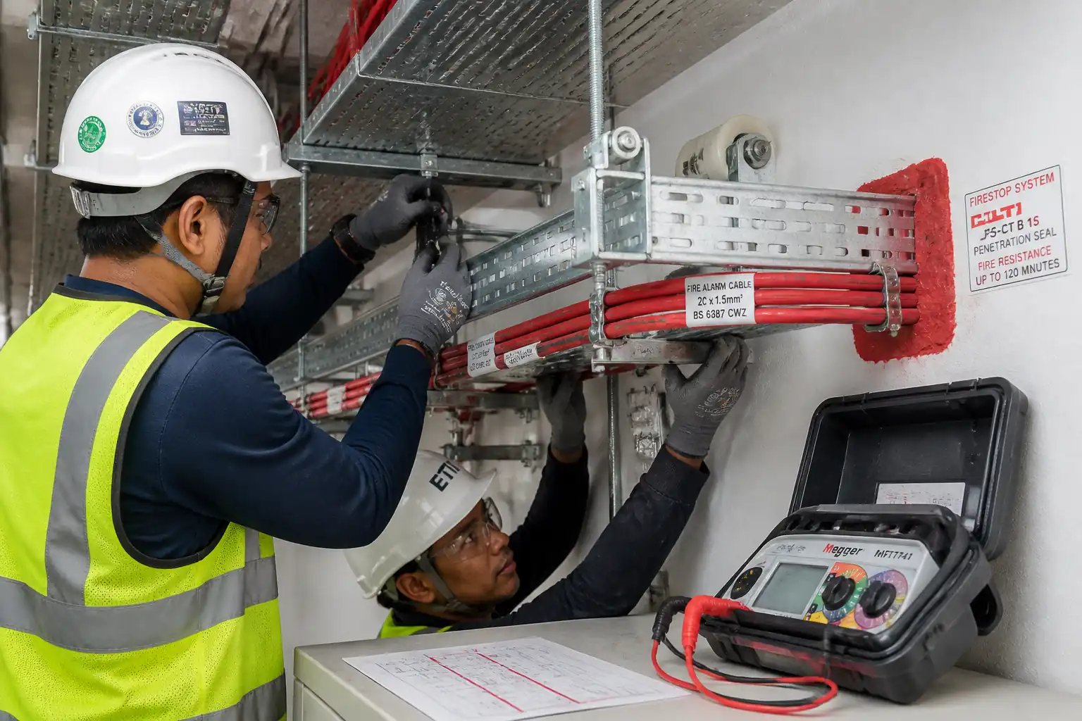
| 4 | Cable pulling (pre-termination) | Pull fire-resistant cables with lubricant if approved. Avoid exceeding manufacturer’s pull tension and bend radii. Segregate from LV/EMI cables as specified. | Electricians | IR |
| 5 | Pre-termination tests (cable only) | Before connecting devices, test each circuit: continuity (ring/loop and CPC if provided) and insulation resistance between conductors and to earth. | QA/QC + Electricians | W |
| 6 | Device base installation and labeling | Fix detector bases, sounder plates, MCP boxes. Provide ferrule labels at both ends and every enclosure/change of direction. Fit address labels as per schedule. | Electricians | IR |
| 7 | Termination and polarity check | Terminate per OEM: observe polarity on addressable loops and notification circuits; fit EOL device where conventional; install isolator bases as designed. | Electricians | IR |
| 8 | Addressing/programming (addressable) | Program device addresses using OEM tools; cross-check against device schedule and drawings; apply barcoded/printed labels. | Commissioning Engineer | W |
| 9 | Conditional: Post-termination verification (no megger) | With devices connected, perform low-voltage continuity and earth-fault scans via loop tester/FACP only. Do not apply IR megger to circuits with electronics attached. | QA/QC + CxE | IR |
| 10 | Protection during construction | Fit OEM dust covers; defer detector heads installation until wet/dusty trades complete. If temporarily installed, bag and remove for cleaning as needed. | Electrical Supervisor | IR |
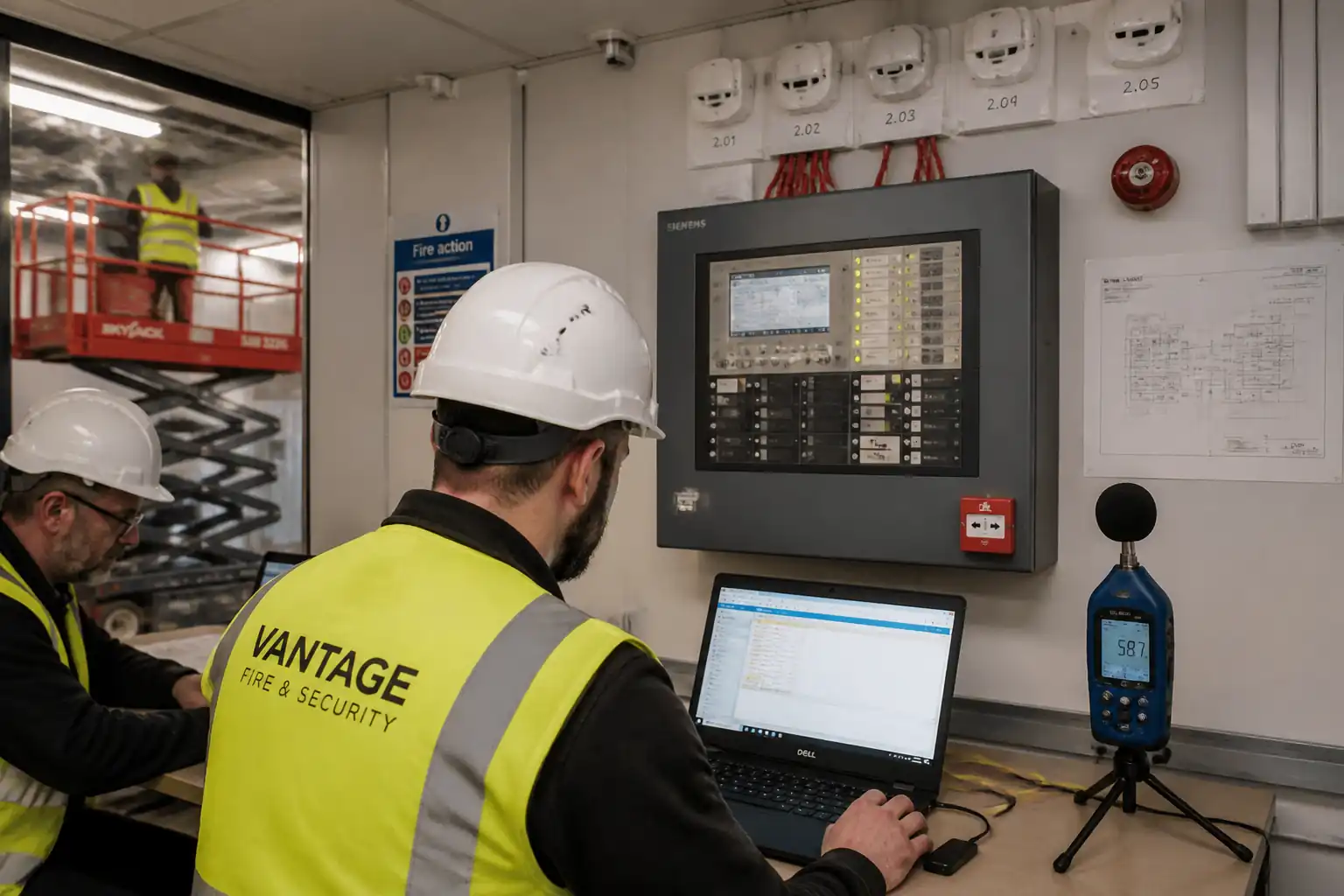
| 11 | Power-up and pre-commissioning | Energize PSUs/FACP under permit. Verify mains supply, battery polarity and capacity, charger operation, fault monitoring, loop cards. Upload base configuration per cause & effect. | Commissioning Engineer | W |
| 12 | Functional testing – detectors | Test 100% of detectors. Use aerosol smoke for smoke detectors; controlled heat source for heat detectors. Confirm device LED, panel event, correct zoning/location text. | QA/QC + CxE + Consultant | H |
| 13 | Functional testing – MCPs | Activate each MCP with test key; verify event and location text; confirm sounders/VADs respond per cause & effect as required for test stage. | QA/QC + CxE | W |
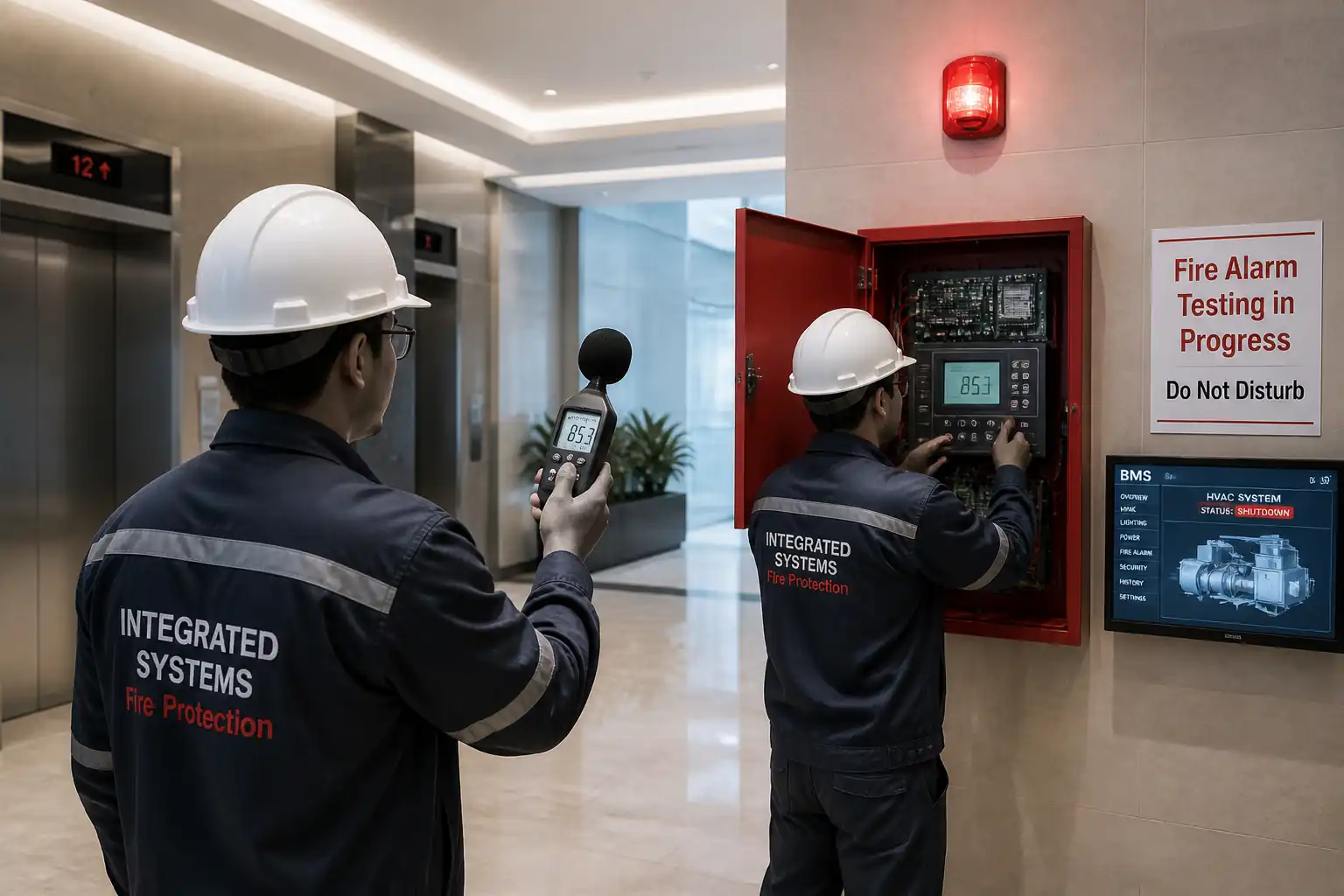
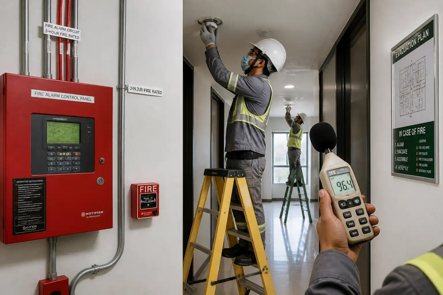
| 14 | Notification appliances performance | Measure SPL at representative points: ≥65 dB(A) or ≥5 dB(A) above ambient (whichever higher), and ≥75 dB(A) at pillow in sleeping risk [Verify standard]. Verify VAD coverage per EN 54-23 classification or NFPA 72 candela and spacing rules. | QA/QC | W |
| 15 | Cause & effect and interface checks | Verify activation triggers programmed outputs (e.g., door release, AHU shutdown, lift homing) using simulated signals and permits. | CxE + BMS/MEP reps | W/H |
| 16 | Fire-stopping of penetrations | Seal cable/containment penetrations with approved systems; label firestops with system ID and FR rating. | Certified firestop installer | W |
| 17 | Final documentation and handover prep | Compile as-builts, device lists with addresses/locations, test records, calibration certs, O&M manuals, training records, spare parts list. | PM + QA/QC | H |
Safety Controls
Key Task-Specific Hazards and Controls
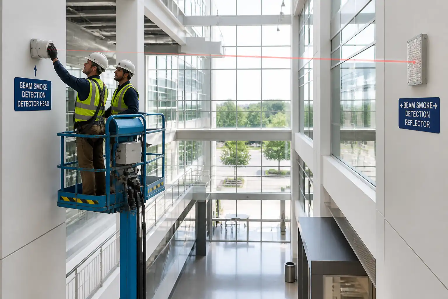
1) Work at height (ladders/MEWPs)
- Hazard: Falls, dropped objects.
- Consequence: Serious injury/fatality.
- Engineering/procedural control: Use podium steps/towers/MEWPs selected by access risk; 3 points of contact on ladders; tools tethered; exclusion zone below; MEWP pre-use checks and harness with short lanyard where required.
- Required PPE: Hard hat with chin strap, safety shoes, gloves, eye protection, fall-arrest harness for MEWP as applicable.
- Collective preventive measure: Edge protection/guardrails on platforms; toe boards.
- Inspection/permit/supervision: Work at Height permit; daily equipment inspections; competent operator certification [Verify per project HSE plan and local regulations].
2) Drilling and fixing overhead
- Hazard: Dust, noise, flying debris, silica exposure; hitting embedded services.
- Consequence: Respiratory harm, eye injury, service strike.
- Engineering/procedural control: Scan surfaces (as-built/utility detector) before drilling; use dust extraction and wet methods if allowed; fit depth stops; barrier off area.
- PPE: Safety glasses/face shield, FFP2/FFP3 respirator, gloves, hearing protection.
- Collective measures: Local exhaust ventilation (HEPA vac), noise barriers if needed.
- Inspection/permit/supervision: Task-specific RA; tool PAT; verify permits near restricted areas.
3) Electrical energy (ELV and mains to PSUs)
- Hazard: Electric shock, arcing during PSU/battery connection.
- Consequence: Shock, burns, fire.
- Controls: Lockout/tagout of mains circuits; verify isolation; correct battery polarity; use insulated tools; no live working unless authorized.
- PPE: Insulated gloves, eye protection.
- Collective measures: Barriers/signage around energized panels.
- Inspection/permit/supervision: Electrical PTW; competent electrician supervision.
4) Manual handling of batteries/equipment
- Hazard: Strains; acid exposure (VRLA/AGM spill risk low but present).
- Consequence: Musculoskeletal injury; chemical burns.
- Controls: Team lifts; trolleys; keep upright; use spill kit nearby; follow OEM MSDS.
- PPE: Nitrile gloves, safety shoes, eye protection.
- Collective measures: Handling aids, clear routes.
- Inspection/permit/supervision: Manual handling training; MSDS available.
5) Fire-stopping chemicals/sealants
- Hazard: VOCs/skin contact.
- Consequence: Irritation, sensitization.
- Controls: Use low-VOC products; ventilation; follow SDS; avoid mixing incompatible products.
- PPE: Nitrile gloves, goggles.
- Collective measures: Local ventilation.
- Inspection/permit/supervision: SDS review; product approval; applicator competency.
6) Working in occupied areas
- Hazard: Public exposure to noise/dust; accidental alarm activation causing panic.
- Consequence: Injury, disruption.
- Controls: Out-of-hours work where possible; isolate zones for testing; notify stakeholders; signage and barriers; use silent test modes where permissible.
- PPE: High-visibility vest, hearing protection as needed.
- Collective measures: Temporary partitions; spotters/marshals.
- Inspection/permit/supervision: Permit to Work; stakeholder notifications and schedule approvals.
7) Exposure to aerosols/heat during testing
- Hazard: Irritant aerosols; burns from heat gun.
- Consequence: Respiratory/eye irritation; minor burns.
- Controls: Use OEM-approved test aerosols in short bursts; heat gun with temperature control and safe distance; ventilate area.
- PPE: Safety glasses, gloves, FFP2 mask as needed.
- Collective measures: Local ventilation; restrict access during tests.
- Inspection/permit/supervision: Toolbox talk; follow OEM test procedures.
8) Ladder/step misuse for MCP heights and corridor devices
- Hazard: Overreach, unstable footing.
- Consequence: Falls.
- Controls: Position ladder at 4:1 ratio; maintain three-point contact; move ladder frequently; use podium where repetitive work expected.
- PPE: Hard hat, non-slip footwear.
- Collective measures: Use podium steps.
- Inspection/permit/supervision: Supervisor spot checks; ladder inspections logged.
Environmental Controls
Environmental Risks and Mitigations
- Dust and noise from drilling: Use HEPA extraction, damp drilling where allowed, schedule noisy works off-peak; maintain noise below site limits [Verify per project].
- Waste segregation: Collect cable offcuts, packaging, empty aerosol cans, and used batteries separately; dispose/recycle via licensed handlers; keep manifests.
- Hazardous substances: Store sealants and aerosols in ventilated, bunded cabinets; follow SDS.
- Fire integrity: Maintain compartmentation; any penetrations sealed immediately with approved systems; record on firestop register.
- Energy use and idling: Switch off tools when not in use; charge batteries on timers; MEWPs shut down when idle.
- Visual/finish protection: Use dust sheets and protect finished surfaces; avoid adhesive tapes that damage finishes.
- Spills: Keep spill kits for chemicals/batteries; report and clean per plan.
- Wildlife/indoor air: Avoid prolonged aerosol use; ventilate during testing; consider occupants with sensitivities—post notices ahead of tests.
QA/QC
Quality Objectives
- Install per approved drawings, OEM manuals, and applicable codes with full traceability of devices and tests.
Inspection and Test Strategy
- 100% inspection of device locations, mounting quality, labeling, and polarity.
- Cable testing: continuity and insulation resistance before device connection (500 V DC typical per IEC 60364-6 for cables only) with ≥1 MΩ minimum [Verify per project]. After device connection, low-voltage testing only.
- Functional testing: 100% of detectors, MCPs, sounders, and VADs. Record response at FACP and outputs.
- Sound level verification: SPL measurements at representative positions including sleeping accommodations where applicable.
- Cause & effect verification: 100% of programmed interactions demonstrated or sample-tested where permitted by Engineer/AHJ [Verify].
Tolerances and Workmanship
- Device alignment: plumb/level within ±2 mm; concentric ceiling mounting; flush plates/escutcheons tight to finish.
- MCP height: 1.4 m ±0.2 m AFFL unless otherwise specified.
- Detector spacing: As per OEM/standard for ceiling height and environment; typical benchmarks: smoke detectors coverage 60–80 m²; heat detectors 20–50 m² depending on class [Verify per standard and project]. Maintain distances from obstructions and in dead air spaces per NFPA 72/BS 5839-1/EN 54-14 [Verify].
Records and Deliverables
- WIRs/IRs, cable test sheets, device test sheets, SPL logs, VAD coverage confirmations, pre-commissioning sheets, C&E sign-off, calibration certificates, firestop register, redlined drawings, as-builts, O&M manuals, training attendance.
Nonconformance and Corrective Action
- Log NCRs for deviations; investigate root cause; implement corrective actions; retest affected circuits/devices.
Hold and Witness Points
- As listed in ITP section; no concealment before IR approval (e.g., above-ceiling works).
Attachments
Included/Referenced Templates
- Material inspection checklist (fire alarm devices and cables)
- Cable test sheet (continuity/insulation resistance)
- Device functional test sheet (smoke/heat/MCP)
- SPL measurement log sheet
- VAD coverage verification worksheet
- Firestop register template
- Pre-commissioning checklist (FACP/PSU)
- Sample redline/as-built mark-up legend
Drawings and Manuals
- Approved shop drawings: device layout, loop schematics, risers
- OEM installation manuals and programming guides
Permits and HSE Documents
- PTWs (Electrical, Work at Height)
- RAMS and toolbox talk attendance
- Calibration certificates for instruments
Records for Handover
- As-built drawings (PDF + CAD/BIM)
- Final ITP/ITR packs signed by Consultant
- O&M manuals including spares and warranty certificates
This content is a read-only public reference. Download or customize to get an editable version.
ITP preview
The first inspection activities from the linked ITP for Method Statement: Fire Alarm Detection and Notification Devices Installation:
| Activity | Inspection / Test | Acceptance Criteria | Responsibility | Record |
|---|---|---|---|---|
| Material receipt and certification | Check model numbers, approvals (EN 54/UL), certificates of conformity, calibration certs for instruments | Matches approved submittals; certifications valid | QA/QC, Consultant | Material inspection report |
| Setting out and mounting heights | Spot-check locations and heights against drawings | Within tolerance (e.g., MCP 1.4 m ±0.2 m AFFL) [Verify] | Supervisor, QA/QC, Consultant | IR/Checklist |
| Containment and back boxes | Fixing quality, spacing, firestop sleeves provision, segregation | Secure, aligned ±2 mm; metallic fixings; segregation per spec | Supervisor, QA/QC | IR with photos |
Showing 3 of 12 inspection activities. View full ITP →
Related Inspection and Test Plan
An Inspection and Test Plan (ITP) is available for Method Statement: Fire Alarm Detection and Notification Devices Installation. The ITP defines the inspection activities, acceptance criteria, hold and witness points, responsible parties, and records required to verify the work described in this method statement.
View the Method Statement: Fire Alarm Detection and Notification Devices Installation ITP →Frequently asked questions
Continue with related Quollnet resources connected to this method statement.