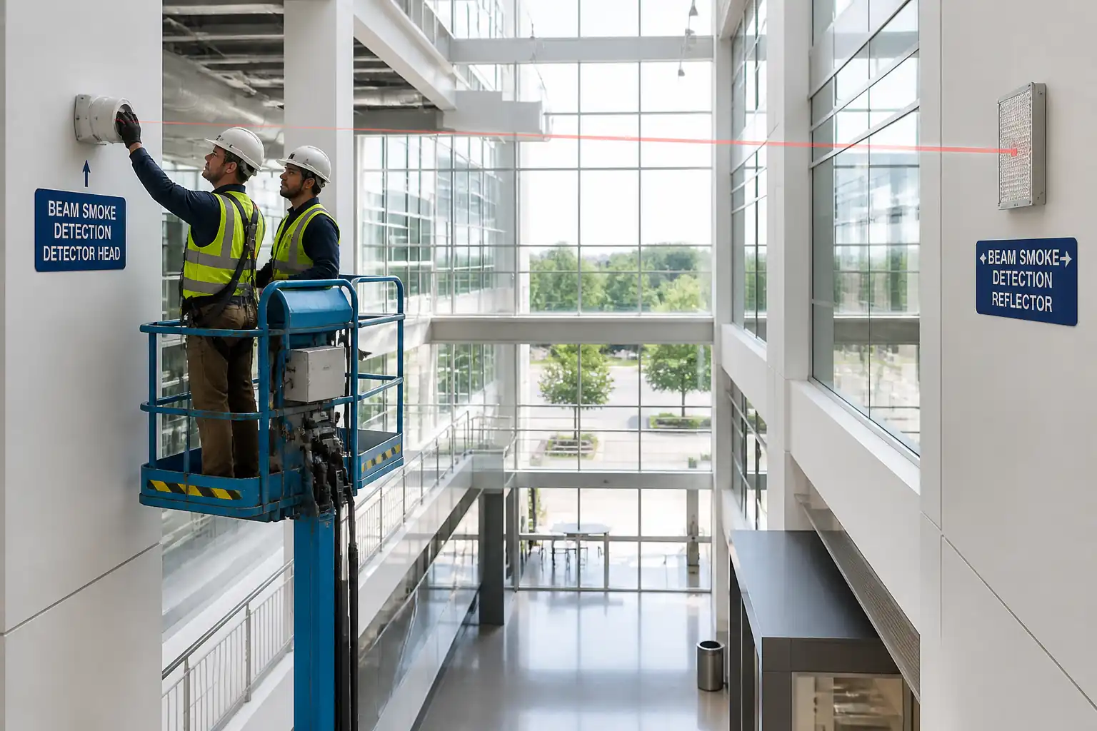

Method Statement – Beam Smoke Detector Installation (Atria, Warehouses, Large Open Spaces) – Method Statement
AI-assisted method statement with matching ITP, PDF download, and Excel export.
More than a static template
Unlike a downloadable Word or PDF template, this method statement is an AI-assisted editable starting point connected directly to a matching Inspection and Test Plan. Every section is structured, project-adaptable, and ready to export.
- AI-assisted drafting — Customize every section with AI for your specific project scope.
- Linked ITP — A matching inspection and test plan is generated alongside the method statement.
- Multiple export formats — Download as a formatted PDF or editable Excel spreadsheet.
- Editable starting point, not a final document — Review, verify, and adjust all content against your project requirements before use.
Static template vs. Quollnet workflow
| Feature | Static template | Quollnet |
|---|---|---|
| Project-specific content | Manual fill-in required | AI-assisted customization |
| Linked ITP | Separate document, no link | Matching ITP included |
| Export formats | Usually PDF only | PDF and Excel |
| Structured sections | Free-form layout | 13 standardized sections |
| Saved to your account | Local file only | Cloud-saved, reusable |
| Content accuracy | You verify everything | AI-assisted, you still verify |
| Cost | Often free but time-intensive | Free to customize and download |
What you can customize
When you save this method statement to your account, every section becomes editable. The following 13 sections are included:
- Scope — Defines the activity and its boundaries.
- References — Standards, specifications, and drawings.
- Responsibilities — Roles and accountabilities.
- Resources — Labour, plant, and equipment summary.
- Materials — Materials and compliance requirements.
- Equipment — Tools and equipment details.
- Prerequisites — Hold points and pre-conditions.
- Method sequence — Step-by-step construction sequence.
- Safety controls — HSE risk controls and PPE.
- Environmental controls — Environmental mitigation measures.
- QA/QC — Quality inspection and test requirements.
- ITP — Inspection and Test Plan table (has its own page).
- Attachments — Referenced drawings and documentation.
Why this method statement is used
This method statement is used to define and communicate the approved procedure for carrying out method statement – beam smoke detector installation (atria, warehouses, large open spaces) on site. It ensures the work is planned in advance, the correct resources and controls are in place, and all personnel understand responsibilities, sequence, quality requirements, and safety controls before work begins. It aligns site execution with the documented scope and acceptance expectations.
Who uses this method statement
This method statement is used by contractors, site supervisors, project engineers, QA/QC engineers, HSE officers, consultants, and client representatives. It serves as a shared reference for planning, execution, supervision, inspection, and approval of the activity on site.
When it is prepared and submitted
The method statement is prepared before the work activity starts and submitted as part of the pre-construction documentation package for review and approval.
Who reviews or approves it
The method statement is usually submitted to the client representative, consultant, resident engineer, or project management consultant for review and approval before the work commences.
Important approval note
This method statement is an AI-assisted editable starting point, not a pre-approved document. Before use on any project, all content must be reviewed and approved by the relevant parties (superintendent, principal contractor, or client representative) in accordance with your contract and project quality plan.
For example: if your specification requires a departure from a referenced standard, that departure must be documented and approved separately — this method statement will not capture that automatically. Always verify against your applicable drawings, specifications, and regulatory requirements.
Method statement content
Scope
Overview
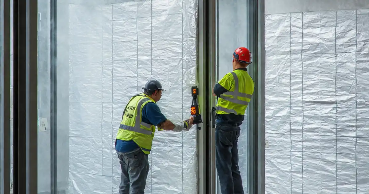
This method statement covers the end-to-end installation, alignment, testing, and commissioning of optical beam smoke detectors (projected or reflective types) in atriums, warehouses, and large open spaces. It includes transmitter/receiver or combined head and reflector alignment, obstruction verification, access equipment safety, cable termination, sensitivity and delay configuration, functional testing, QA/QC hold points, and final commissioning records.
Inclusions
- Review of design/shop drawings, coordination, and permits.
- Installation of device backboxes/brackets, beam heads, reflectors, and accessories.
- Fire-rated cabling and containment (first and second fix), termination, and labeling.
- Alignment, sensitivity adjustment, signal strength optimization, and compensation settings.
- Obstruction survey and signage to protect the beam path.
- Interface to fire alarm control panel (FACP), address programming, and cause-and-effect tests.
- Functional testing (alarm/fault), records, as-built documentation, and handover.
Exclusions
- Structural steelworks or major architectural modifications beyond minor fixings.
- Smoke control system commissioning (handled by dedicated system specialist) except interface verification.
- Permanent power supply works upstream of the fire alarm power supply unit.
References
| Document Type | Reference / Number | Revision | Notes |
|---|---|---|---|
| Code | NFPA 72 | Location, testing, maintenance guidance. | |
| Standard | BS EN 54-12 | Applies to EU/UK certified devices. | |
| Standard | ISO 7240-12 | ||
| Standard | IEC 60364 / NFPA 70 | Segregation, earthing, containment. | |
| Standard | BS 7629-1 / BS 7846 / UL 1424 | Select per project and AHJ. | |
| Code/Listing | UL Systems / ETA | ||
| HSE | [Verify per project HSE plan and local regulations] | PTW, LOTO, hot works, rescue plan. |
Responsibilities
| Role | Responsibility | Name / Party |
|---|---|---|
| PM | Ensure compliance with specs and schedule; approve method and ITP. | Main Contractor |
| QA/QC | Issue inspection requests; verify hold/witness points; maintain QA dossiers. | Main Contractor |
| HSE | Approve PTW; verify operator competencies; conduct audits. | Main Contractor |
| Supervisor | Brief crew; check fixings, cabling terminations, labeling. | Main Contractor |
| Specialist | Program addresses; perform functional tests; complete commissioning records. | Approved Subcontractor |
| Operator | Pre-use checks; operate under permit; maintain exclusion zone. | Main/Subcontractor |
| AHJ/Consultant | Review documentation; witness commissioning as required. | Independent |
Resources
| Resource Type | Description | Quantity | Remarks |
|---|---|---|---|
| Labour | Install containment, cabling, and devices at height. | As per project | |
| Technician | Address programming, alignment, testing. | As required | |
| Equipment Crew | Operate MEWP and ground guidance. | Per MEWP |
Materials
| Material | Specification / Grade | Quantity | Remarks |
|---|---|---|---|
| Detector | As per BOQ | ||
| Reflector/Receiver | |||
| Cable | |||
| Containment | |||
| Anchors | |||
| Labels |
Equipment
| Equipment | Capacity / Type | Quantity | Inspection Required |
|---|---|---|---|
| MEWP | As required | Yes | |
| Per person | Yes | ||
| 1–2 | Yes | ||
| 1 | Yes | ||
| 1 | Yes | ||
| 1 | Yes | ||
| 1 | No |
Prerequisites
- Approved shop drawings, datasheets, method statement, and ITP.
- Material approvals (MIRs) for detectors, cables, fixings.
- Confirm locations, mounting heights, beam lengths, and zoning with designer/AHJ.
- Permits to work: Work at Height, MEWP, Hot Work (if drilling creates sparks) [Verify per project HSE plan and local regulations].
- Fire alarm impairment/disablement coordinated with Client/Monitoring Center; temporary fire watch arranged.
- Access plan: MEWP selection, ground bearing verification, exclusion zones, rescue plan and trained personnel.
- Cable routes coordinated with other trades to avoid future obstructions along beam paths.
- Power/loop availability verified; panel powered and healthy; address range reserved.
- Calibrated test instruments available with valid certificates.
- Pre-install cable tests planned: continuity and insulation resistance prior to device connection (no meggering through devices).
Method Sequence
| Step | Activity | Description | Responsibility | Inspection / Hold Point |
|---|---|---|---|---|
| 1 | Pre-Start Briefing and Hazard Review | Conduct toolbox talk addressing work at height, MEWP operation, laser eye safety, drilling, and fire alarm impairment. | Supervisor/HSE | Toolbox attendance |
| 2 | Obstruction Survey & Layout | Verify beam head and reflector/receiver positions against drawings; survey for permanent/temporary obstructions (ducts, cranes, signage, banners, doors). Define clearance envelope along beam path. | Supervisor/FA Specialist | Visual with measure |
| 3 | Containment Installation (If required) | Install conduits/trunking and fire-rated cable supports using non-combustible fixings. | Electricians | QC inspection |
| 4 | Cable Pulling – First Fix | Pull fire-rated cables to device locations; leave sufficient slack for termination; avoid sharp bends and segregation breaches. | Electricians | Continuity check |
| 5 | Bracket/Backbox Fixing | Core drill and fix mounting brackets/backboxes for head and reflector/receiver per template; use anchors suitable for substrate. | Electricians | Pull-test (if required) |
| 6 | Device Mounting | Install beam head and reflector(s)/receiver onto brackets; do coarse alignment using bubble/laser tools. | Electricians/FA Specialist | Visual |
| 7 | Cable Termination & Labeling | Terminate per polarity and manufacturer; use ferrules; maintain segregation; label device address and loop/core IDs. | Electricians | QC check |
| 8 | Panel Integration & Programming | Program device addresses/IDs; map to zones; set cause-and-effect per matrix; disable unwanted alarms during commissioning. | FA Specialist | Panel log review |
| 9 | Fine Alignment & Sensitivity/Delay Settings | Use built-in alignment indicators or handheld tool to maximize signal; set obscuration sensitivity and alarm/fault delays per environment. | FA Specialist | Measured signal strength |
| 10 | Beam Path Protection & Signage | Install “Beam Path – Keep Clear” signage and demarcation; brief facility team to avoid future obstructions. | Supervisor | Visual |
| 11 | Functional Testing – Fault | Induce fault (misalignment/cover lens) to verify fault signaling at FACP and reset behavior. | FA Specialist/QA-QC | FACP indication |
| 12 | Functional Testing – Alarm | Use manufacturer-approved obstruction plate/test filter or approved aerosol method to simulate smoke across beam. | FA Specialist/QA-QC | FACP alarm, sounder/C&E |
| 13 | Restoration & Housekeeping | Remove debris; restore finishes; seal penetrations; remove access equipment; re-enable fire system and notify stakeholders. | Supervisor | Area walkdown |
| 14 | Documentation & Handover | Compile commissioning sheets, alignment readings, device schedule, as-builts, O&M manuals, warranties, training records. | QA/QC & FA Specialist | Document review |
Health & Safety Controls
Key Hazards, Consequences, and Controls
1) Working at height (MEWP/scaffold)
- Consequence: Falls leading to serious injury/fatality.
- Controls: MEWP selection per reach; ground bearing assessment; use guardrails and short lanyard to anchor points; maintain exclusion zone with barriers; no leaning from basket; wind threshold per OEM [Verify].
- PPE: Helmet with chin strap, full-body harness with lanyard, safety boots, gloves, hi-vis, eye protection.
- Collective measure: Properly maintained MEWP with guardrails; spotter/banksman.
- Inspection/Permit: MEWP certificate (LOLER), pre-use checklist, Work at Height PTW; supervisor sign-off; rescue plan and drill documented.
2) Drilling/Anchoring into concrete/steel
- Consequence: Flying debris, silica dust inhalation, hit rebar/services.
- Controls: Survey with wall/steel scanner; dust extraction with HEPA; select anchors per substrate; use torque-limited tools; hot works control if sparking.
- PPE: Safety glasses/face shield, FFP2/FFP3 mask or P100 respirator [Verify], gloves, hearing protection.
- Collective measure: Local exhaust ventilation; barriers to segregate work zone.
- Inspection/Permit: Hot work permit if required; anchor pull-test plan where specified; PAT of tools.
3) Electrical low-voltage work
- Consequence: Shock, short circuit, device damage during testing.
- Controls: Isolate circuits; lockout/tagout for power supplies; never insulation-test through devices; verify polarity and earth continuity before energizing.
- PPE: Insulated gloves (as needed), eye protection.
- Collective measure: Use of fused leads on meters; supervised energization.
- Inspection/Permit: Electrical PTW/LOTO; supervisor sign-off.
4) Laser alignment exposure
- Consequence: Eye injury from direct/reflected beam.
- Controls: Use Class 1/2 devices only; avoid eye-level exposure; do not stare into beam; place warning signs during alignment.
- PPE: Safety glasses if recommended by OEM.
- Collective measure: Controlled access during alignment.
- Inspection/Permit: OEM manual compliance; supervisor oversight.
5) Public/third-party interface in atriums/warehouses
- Consequence: Struck-by from tools/materials; unauthorized entry under MEWP.
- Controls: Exclusion barriers and signage; spotter at ground; tool lanyards; schedule during low-occupancy periods.
- PPE: Hi-vis, safety footwear, hard hat.
- Collective measure: Taped/railed cordons; overhead protection if necessary.
- Inspection/Permit: Site traffic plan; permit to work; daily HSE inspection.
6) Noise and vibration
- Consequence: Hearing damage; disturbance to occupants.
- Controls: Use low-noise drills; limit working hours; hearing protection.
- PPE: Ear defenders/plugs.
- Collective measure: Acoustic screens where practicable.
- Inspection/Permit: Compliance with site noise limits [Verify].
7) Housekeeping and dropped objects
- Consequence: Injuries, equipment damage.
- Controls: Keep basket tidy; use parts trays; tether small tools; no throwing of materials from height.
- PPE: Standard site PPE.
- Collective measure: Toe-boards in basket; debris nets if needed.
- Inspection/Permit: Daily housekeeping inspection.
8) Fire alarm impairment during testing
- Consequence: Undetected fire; false evacuations.
- Controls: Impairment notice; temporary fire watch; isolate outputs as needed; restore and test post-works.
- PPE: N/A.
- Collective measure: Communication to security and occupants.
- Inspection/Permit: Impairment permit; authorization per client policy.
Environmental Controls
- Dust from drilling: Use vacuum shrouds and HEPA filtration; damp wipe surfaces after work; avoid dust release into HVAC returns.
- Noise: Schedule noisy tasks during permitted hours; use low-vibration/low-noise tools; monitor levels if required [Verify].
- Waste management: Segregate packaging, cable offcuts, and anchor debris; dispose per site waste plan; recycle metals and cardboard.
- Penetration firestopping: Use low-VOC, approved sealants; avoid over-application; maintain listing details in as-builts.
- Test aerosols/obstruction plates: Use manufacturer-approved, non-toxic agents; ventilate if aerosol used; prevent nuisance alarms outside test area.
- Spills: Keep spill kits for chemical anchors; prevent resin discharge; cure and dispose per MSDS.
- Energy/MEWP idling: Switch off equipment when idle; charge batteries during off-peak if applicable.
- Environmental permits: Verify local requirements for dust/noise; comply with project Environmental Management Plan [Verify per project HSE plan and local regulations].
Quality Assurance and Quality Control
Submittals and Records
- Approved datasheets and product certifications (EN/UL/ISO compliance).
- Cable test certificates (continuity, insulation resistance pre-termination).
- Anchor data sheets and pull-test reports (where specified).
- Alignment records: beam length, mounting height, signal strength %, sensitivity, delay settings, drift compensation status.
- Panel programming printouts and event logs.
- Functional test and cause-and-effect verification sheets.
- As-built drawings and device schedules with addresses and coordinates.
Hold and Witness Points
- HP1: Bracket/backbox installation and anchors verified before device mounting.
- HP2: Fine alignment and sensitivity settings completed and recorded before functional testing.
- HP3: Functional alarm test and cause-and-effect – AHJ/Consultant witness if required.
- HP4: Handover dossier review – completion of all records and approvals.
- WP1: Cable terminations and labeling prior to energization.
- WP2: Fault simulation test prior to full alarm testing.
Tolerances and Acceptance (Typical – Verify per project)
- Mounting plumb/level: ±2 mm/m.
- Beam head and reflector alignment: achieve signal strength within OEM “good” band (e.g., ≥70–90%).
- Sensitivity: 25–35% obscuration for clean, low-dust spaces; adjust per risk/design [Verify].
- Alarm delay: typically 10–20 s; fault delay per OEM [Verify].
- Cable IR (before device connection): ≥20 MΩ at 500 V DC.
- Labeling: device address visible at point of device and on drawings.
Testing Frequencies (Construction phase)
- 100% inspection of installations.
- 100% functional testing of each beam detector (alarm and fault).
- Re-test after any alignment change or obstruction change.
Nonconformance
- Record NCRs for any deviation; agree corrective action; re-test; update documentation.
Attachments
- Approved shop drawings and device layout with beam paths and clearance envelopes.
- Manufacturer datasheets and installation manuals for beam detectors and reflectors.
- Risk Assessment and Method Statement (RAMS) including MEWP rescue plan.
- Cable test sheets (continuity and insulation resistance).
- Alignment and configuration record sheets (signal %, sensitivity, delays, drift compensation).
- Commissioning and cause-and-effect verification sheets.
- Material Inspection Requests (MIRs), certificates of conformity, calibration certificates.
- Fire alarm impairment permits and restoration log.
- As-built drawings and device schedules with addresses and GPS/grid references (if used).
This content is a read-only public reference. Download or customize to get an editable version.
ITP preview
The first inspection activities from the linked ITP for Method Statement – Beam Smoke Detector Installation (Atria, Warehouses, Large Open Spaces):
| Activity | Inspection / Test | Acceptance Criteria | Responsibility | Record |
|---|---|---|---|---|
| Material receipt – Detectors, reflectors, accessories | Check certificates, model, quantities, damage | Compliant with approved submittals; EN/UL/ISO listed; no damage. | QA/QC, Storekeeper | MIR, CoC, delivery notes |
| Containment installation | Visual inspection, measurements | Supports spacing and materials per spec; penetrations sealed with approved systems. | QA/QC, Supervisor | IR, photos |
| Cable tests – Pre-termination | Continuity and IR (cable-only) | Continuity correct; IR ≥20 MΩ at 500 V DC [Verify]. | QA/QC, Electrician | Cable test sheet |
Showing 3 of 11 inspection activities. View full ITP →
Related Inspection and Test Plan
An Inspection and Test Plan (ITP) is available for Method Statement – Beam Smoke Detector Installation (Atria, Warehouses, Large Open Spaces). The ITP defines the inspection activities, acceptance criteria, hold and witness points, responsible parties, and records required to verify the work described in this method statement.
View the Method Statement – Beam Smoke Detector Installation (Atria, Warehouses, Large Open Spaces) ITP →Frequently asked questions
Continue with related Quollnet resources connected to this method statement.