Install contiguous pile wall—cage and concreting checklist guides site engineers through verifying cage cover, centralizers, tremie placement, and pile continuity during bored contiguous wall construction.
- Verify cage cover, centralizers, and tremie embedment before concreting.
- Reduce defects and delays by standardizing acceptance criteria and evidence.
- Interactive, commentable checklist with export and QR code verification.
- Ensure pile continuity and clean displacement in slurry-supported bores.
The checklist
Pre-Concreting Checks
- Confirm latest approved drawings/specifications and method statement for cover, centralizers, tremie, and sequence are on site; acceptance: current revision stamped; evidence: upload revision and approval pages.
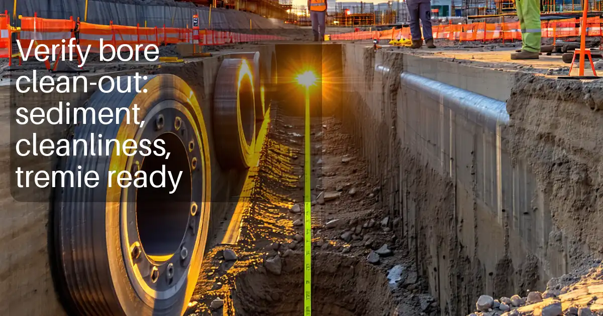
- Measure sediment at borehole base using weighted tape or spoon; acceptance: ≤ 50 mm residual sediment; evidence: recorded depth reading and photo.
- Check slurry properties (if used) with Marsh funnel, mud balance, and sand kit; acceptance: density 1030–1150 kg/m³, viscosity 32–50 s, sand ≤ 4%; record results.
- Confirm borehole diameter and verticality with caliper/inclinometer; acceptance: diameter ≥ design, verticality deviation ≤ 1:200; attach instrument report.
- Verify concrete mix and logistics; acceptance: slump 180–220 mm at tremie discharge; cast test specimens; evidence: batch tickets, slump photo, specimen IDs.
Reinforcement Cage
- Measure cage overall length and tip level against design; acceptance: tip elevation not higher than design, allowable lower tolerance −50 mm; evidence: tape measurement log.
- Check bar diameters and quantities with calipers and count; acceptance: matches drawing; record heat/lot numbers; evidence: photos of tags and bars.
- Verify hoop/spiral pitch using a steel tape; acceptance: within ±10 mm of specified spacing; record three readings per 3 m length.
- Inspect splices/couplers; tighten with calibrated torque wrench to manufacturer’s requirement; acceptance: wrench reading within ±5% of specified torque; capture torque log.
- Install temporary stiffeners and lifting frames; acceptance: cage out-of-round ≤ 10 mm over nominal diameter; evidence: ring gauge check and photos.
Centralizers and Cover
- Install polymer centralizers at 1.5–2.0 m vertical spacing, minimum three per level; acceptance: evenly distributed; evidence: count and photo log.
- Confirm centralizer OD achieves cover; acceptance: nominal cover 60 mm ±10 mm, minimum 50 mm at any point; gauge-check and record.
- Verify centralizer material is non-absorbent polymer or approved equivalent; acceptance: no steel-on-soil contact; evidence: supplier and batch recorded.
- Place spacers near toe, joints, and overbreak zones; acceptance: centralizer within 0.5 m of toe and at 1.5–2.0 m intervals upward; photo evidence.
- Dry-fit cage through guide ring before lift; acceptance: consistent all-round cover maintained; evidence: measured offsets at four quadrants.
Tremie Setup and Placement
- Assemble tremie with clean, gasketed joints; acceptance: water test at 0.2 MPa for 5 minutes without leaks; record pressure and duration.
- Select tremie internal diameter ≥ 3× maximum aggregate size and ≥ 150 mm; evidence: measured ID and recorded aggregate size.
- Position tremie tip 150–300 mm above pile base before first charge; acceptance: confirmed by marked tremie lengths; record initial tip elevation.
- Use disposable plug/go-devil for first charge; acceptance: no visible segregation in returns; evidence: observation note and photo if retrieved.
- Maintain tremie embedment ≥ 3.0 m below rising concrete surface; acceptance: continuous embedment log with calculated head; evidence: embedment chart.
Concreting Operations
- Ensure continuous concrete supply; acceptance: interval between trucks ≤ 5 minutes, no cold joints; evidence: delivery timestamps and pump log.
- Monitor concrete rise with weighted tape; acceptance: uniform rise, final head at cut-off +0.5–1.0 m; record readings each 1.0 m.
- Reconcile placed volume against theoretical (πr²h); acceptance: within +10% of theoretical; investigate deviations > 10%; attach calculation sheet.
- Manage slurry displacement and disposal; acceptance: displaced slurry clarity improves; sample and dispose per approved project specifications and authority requirements; record volumes.
- Remove contaminated top if required; acceptance: trim 0.5–1.0 m of weak/segregated concrete; evidence: photos and trimmed depth record.
Continuity and Records
- Follow approved pile sequencing for continuity with adjacent piles; acceptance: documented sequence followed; evidence: pour sequence log with timestamps.
- Survey as-built pile position and cut-off; acceptance: position within ±25 mm of set-out, cut-off ±10 mm; upload survey file and sketch.
- Mark pile ID and pour date at cut-off; acceptance: durable tag fixed to reinforcement; evidence: photo and register entry.
- Cast compressive strength specimens at start and mid-pour; acceptance: minimum 6 specimens labeled; record IDs, ages, and curing method.
- Obtain sign-offs from superintendent, inspector, and contractor; acceptance: digital signatures same day; evidence: uploaded signed checklist.
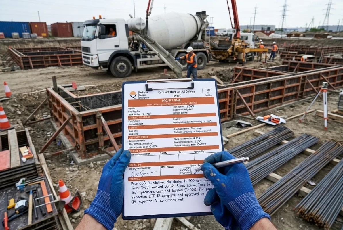
Preview the printable checklist
Preview page one below. Open the image or download the PDF for all pages.

At a glance
- Control concrete quality and reinforcement positioning by verifying cage geometry, centralizer spacing, and minimum cover before any lift. Quantified checks on sediment, slurry, tremie diameter, and embedment reduce segregation and void risk, resulting in durable, continuous piles ready for trimming and capping beam integration.
- Reduce rework by confirming continuous concrete head, uninterrupted supply, and verified rise using weighted tapes. Acceptance windows for slump, embedment, and placed volumes keep operations predictable. Transparent logs of batch tickets, timestamps, and test specimens support inspections and approval without delaying follow-on works.
- Improve traceability with consistent records: bar heat numbers, coupler torque, slurry results, and as-built surveys for position and cut-off. Interactive online checklist with tick, comment, and export features secured by QR code. Supervisors see real-time compliance, corrective actions, and close-out status across multiple piles and shifts.
- Assure pile continuity at wall scale by enforcing pour sequencing, monitoring overlap limits, and reconciling theoretical versus placed volume. Clean displacement of slurry and controlled trimming of contaminated tops protect integrity at the construction joint, reducing infiltration risk and ensuring predictable performance of the contiguous wall.
How to Use This Interactive Cage and Concreting Checklist
- Preparation: assemble tremie pipes and gaskets, centralizers, cover gauges, weighted tape, Marsh funnel, mud balance, sand kit, calipers, torque wrench, guide ring, survey kit, concrete testing gear, and PPE.
- Preparation: confirm access, pump location, concrete delivery schedule, lighting, communications, approved method statement, and permits. Brief crew on sequence, acceptance limits, and evidence to capture.
- Using the Interactive Checklist: open the checklist, select project and pile ID, start interactive mode, and assign a responsible owner for each section.
- Using the Interactive Checklist: tick items as completed, attach photos, enter readings (slump, density, embedment), scan batch tickets, and link instrument reports.
- Using the Interactive Checklist: record nonconformances with comments, assign corrective actions and deadlines, and @mention stakeholders for rapid resolution.
- Export: generate a QR-authenticated PDF/Excel report with all evidence, timestamps, signatures-in-progress, and shareable links for supervisors and inspectors.
- Sign-Off: capture digital signatures from superintendent, inspector, and contractor; lock the record; distribute and archive per approved project specifications and authority requirements.
Reinforcement cage cover and centralizers: achieving uniform clearance
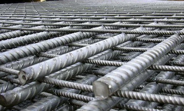
Uniform cover around the reinforcement cage controls durability and structural reliability of contiguous bored piles. Polymer wheel centralizers and spacers should be fixed at 1.5–2.0 m vertical spacing, with additional units near the toe and joints. Dry-fitting the cage through a guide ring verifies that the nominal cover—commonly 60 mm ±10 mm with an absolute minimum of 50 mm—is achieved before lifting. Use calipers to confirm bar sizes, tape measures to check spiral pitch within tolerance, and a calibrated torque wrench for couplers. Temporary stiffeners prevent ovalization during handling, keeping out-of-round within 10 mm. Document heat numbers and spacer batches to maintain traceability. On site, a quick four-quadrant cover check with a gauge or measured offsets provides immediate acceptance evidence, and photographs validate spacer distribution. These practices reduce the chance of steel touching the bore wall, preventing corrosion initiation and maintaining the designed load path from concrete to reinforcement.
- Place centralizers near the toe and at 1.5–2.0 m spacing.
- Target 60 mm cover, never less than 50 mm anywhere.
- Dry-fit cages through a guide ring before lifting.
- Keep out-of-round within 10 mm during handling.
- Record bar heats, spacer batches, and torque values.
Tremie concreting essentials: first charge, embedment, and continuity
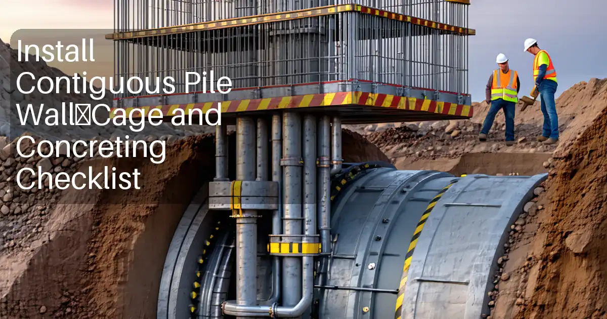
Successful tremie placement depends on a sealed first charge, adequate embedment, and uninterrupted supply. Assemble tremie sections with clean gaskets and prove joints with a brief 0.2 MPa water test. Select an internal diameter at least three times the largest aggregate and no less than 150 mm to limit friction and blockages. Position the tip 150–300 mm above the pile base and launch with a plug or go-devil to prevent washout. Maintain at least 3 m of tremie embedment below the rising concrete head, monitoring with a weighted tape and a simple head calculation. Keep truck intervals under five minutes to avoid cold joints, track batch tickets, and record slump at discharge. Watch returns: clearer displaced slurry and uniform head rise indicate sound displacement. If contamination appears at the top, plan for trimming 0.5–1.0 m after set.
- Water-test tremie joints at 0.2 MPa for 5 minutes.
- Use ID ≥ 150 mm and ≥ 3× aggregate size.
- Maintain ≥ 3 m tremie embedment at all times.
- Keep truck gaps ≤ 5 minutes to prevent cold joints.
- Monitor head rise with a weighted tape.
Wall continuity and quality records: proving performance pile by pile
Contiguous wall performance depends on consistent pile continuity and verifiable records. Follow the approved pour sequence to minimize gaps or misalignment between adjacent piles. Survey as-built positions to within ±25 mm and confirm cut-off within ±10 mm to ensure proper capping beam engagement. Reconcile placed volume against theoretical to detect overbreak or necking; investigate deviations greater than 10%. Maintain a complete evidence file: slurry tests, sediment checks, torque logs, heat numbers, tremie embedment charts, timestamps, and photos. Tag each pile with ID and pour details for traceability, and obtain same-day approvals to keep works flowing. If top contamination is suspected, plan controlled trimming before constructing the capping beam. These measures create a defensible QA trail and help avoid later remediation costs.
- Follow the approved pour sequence for continuity.
- Survey position ±25 mm and cut-off ±10 mm.
- Reconcile actual versus theoretical volume each pile.
- Tag piles with ID and pour date immediately.
- Secure same-day digital approvals and uploads.