Install contiguous pile wall—drilling stage checklist for contractors and inspectors verifying pile spacing, alignment, verticality, and bore cleanliness before concreting, excluding secant walls and post-concrete activities.
- Verify center-to-center spacing and guide wall alignment to drawings.
- Control mast verticality and bore deviation with calibrated instruments.
- Confirm bore diameter, depth, stability, and base cleanliness limits.
- Interactive, commentable, export-ready with QR code verification trail.
The checklist
Pre-Drilling Setup
- Confirm latest drawings, ITP, and hold points; record approvals and version numbers.
- Verify pile IDs and sequence match schedule; mark on guide wall; photo evidence of markings.
- Calibrate drill mast inclination sensor against certified digital level; acceptance ±0.1°; save calibration certificate.
- Inspect rig, kelly, auger/barrel, and casings for wear; record serial numbers and condition photos.
- Confirm subsurface utility clearances using permit and GPR (if required); set exclusion zones; supervisor sign-off.
Layout and Guide Wall
- Set out pile center coordinates with total station; tolerance ±5 mm; upload as-built CSV and sketch.
- Check guide wall straightness and level; deviation ≤5 mm over 5 m; record level readings and photos.
- Mark design pitch (center-to-center spacing) along guide wall; acceptance ±10 mm; photo of each mark.
- Install and verify two independent control benchmarks; cross-check closure ≤6 mm; surveyor signature required.
- Confirm minimum edge distance to existing structures per drawings; measure and record with steel tape; photo.
Drilling and Verticality Control
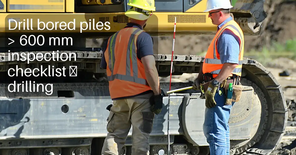
- Center rig over pile mark using laser crosshair; acceptance within ±5 mm; capture rig display screenshot.
- Verify mast verticality with dual-axis inclinometer before drilling; deviation ≤1:200; store inclinometer readings.
- Drill with specified tool diameter; measure bore diameter using calliper/sonar; within +50/−0 mm; record measurements.
- Measure bore depth with weighted tape to design toe/rock socket; tolerance +0/−50 mm; log depth per pile.
- Check cumulative horizontal deviation using downhole inclinometer; limit ≤1% of depth; upload deviation plot.
Ground/Fluid Stability
- Assess groundwater; if support fluid used, maintain fluid head ≥1.0 m above water table; log levels hourly.
- Test support fluid: density 1040–1150 kg/m³, Marsh viscosity 32–60 s, sand ≤4%; attach field test sheets.
- Install temporary casing (if required) plumb within ≤1:200; embed ≥1.5 m into stable stratum; photo verification.
- Monitor penetration rate and torque; flag abrupt changes indicating obstructions/voids; engineer review note attached.
- Survey bore profile via calliper/sonar every 2 m; necking/overbreak >5% diameter triggers NCR and rectification plan.
Bore Cleanliness and Acceptance
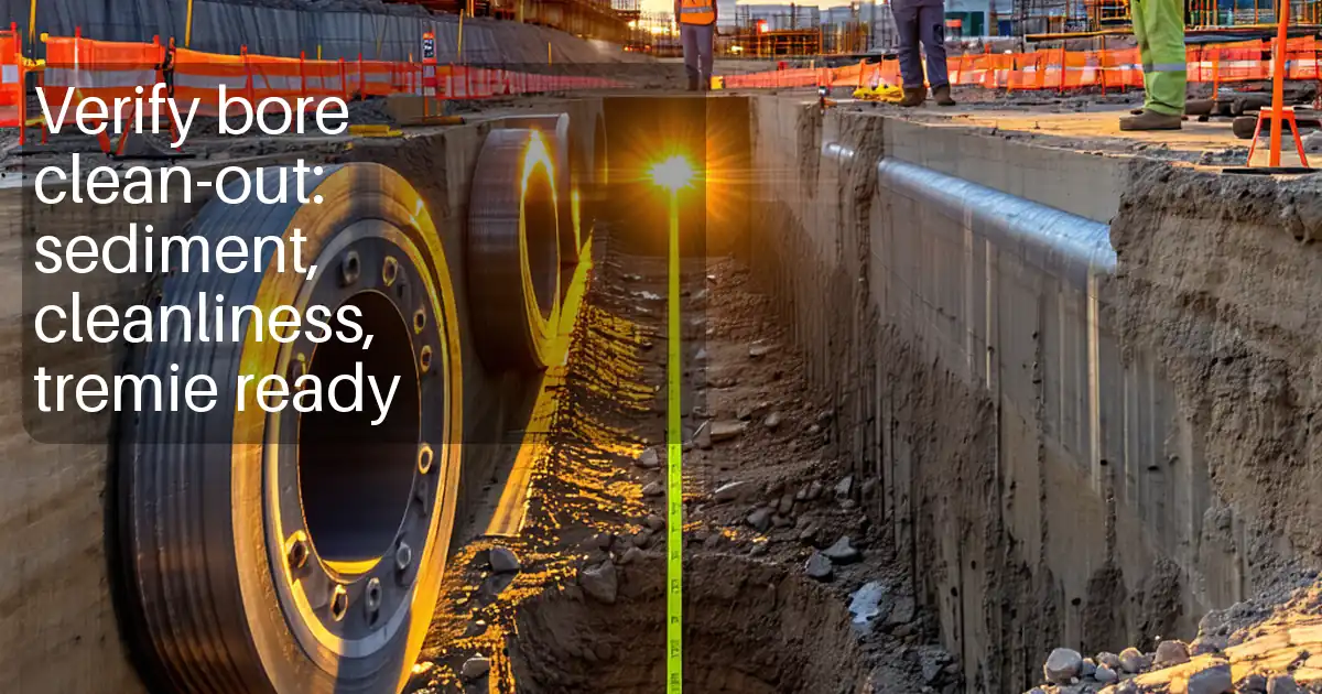
- Circulate support fluid or airlift to remove fines; target return turbidity ≤50 NTU; record sample results.
- Measure base sediment thickness with weighted dip plate; acceptance ≤50 mm; log three readings and average.
- Inspect bore base with downhole camera where feasible; confirm no loose debris; save timestamped images.
- Flush until return fines <3% by mass; retain labeled sample; supervisor verification.
- Confirm center-to-center spacing between adjacent drilled bores equals design pitch ±10 mm; upload survey check.
- Complete pre-concrete inspection and hold-point release per approved project specifications and authority requirements; obtain signatures.
Preview the printable checklist
Preview page one below. Open the image or download the PDF for all pages.

At a glance
- This drilling-stage checklist safeguards contiguous bored pile performance by confirming set-out accuracy, guide wall alignment, mast verticality, and bore stability before concreting. Measurable tolerances and photographic evidence prevent cumulative errors and rework while supporting timely hold-point releases and quality records.
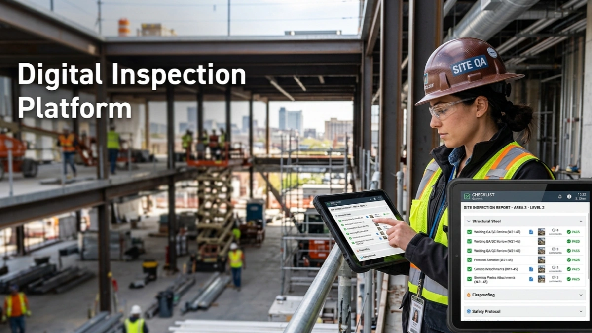
- Interactive online checklist with tick, comment, and export features secured by QR code. It captures survey coordinates, inclinometer readings, slurry test results, turbidity samples, and base sediment measurements—allowing engineers and site supervisors to review, sign off, and archive traceable drilling evidence.
- Practical inspection steps detail tools and acceptance criteria: total station surveys, dual-axis inclinometers, callipers/sonar, Marsh funnel, density balances, and weighted dip plates. The process isolates drilling-only checks—spacing, alignment, verticality, and cleanliness—so teams avoid mixing post-drilling or concreting tasks.
How to Use This Interactive Drilling-Stage Checklist
- Preparation: gather latest drawings, ITP, survey control data, calibrated inclinometer, total station, calliper/sonar, Marsh funnel, density kit, turbidity meter, dip plate, and PPE. Confirm crew briefing and hold-point requirements.
- Open the checklist, select project, chainage, and pile IDs. Enable interactive mode to allow real-time ticking, commenting, and media attachments tied to each inspection item.
- Record measurements directly in the fields provided, attach instrument screenshots and photos, and tag locations. Use tolerance prompts to flag out-of-range values for immediate escalation.
- Add comments for nonconformances and corrective actions. Mention responsible parties, due dates, and link supporting documents per approved project specifications and authority requirements.
- Export results as PDF/Excel for distribution at hold points. Share the QR code to enable quick verification of the latest signed record on site.
- Sign-Off: obtain digital signatures from contractor, consultant, and client representatives. Archive the record with QR authentication to lock revisions and preserve a complete audit trail.
Layout and Guide Wall Control
Accurate layout underpins contiguous pile wall performance. Begin with a certified survey set-out to fix each pile center within ±5 mm and verify two independent control benchmarks. The guide wall governs alignment and pitch; its straightness and level should be checked with a digital level and string line, maintaining ≤5 mm deviation over 5 m. Mark the design pitch along the guide wall and photograph each station, ensuring the center-to-center spacing tolerance is maintained. Confirm edge distances to adjacent structures to avoid undermining and to achieve the intended soil arching between piles. These steps prevent cumulative positional errors that later manifest as gaps, clashes, or inadequate overlap. All observations should be logged with coordinates, sketches, and photos so later drilling data can be tied back to fixed references and verified quickly during hold points.
- Set-out tolerance: pile centers within ±5 mm.
- Guide wall deviation ≤5 mm over 5 m.
- Photograph and label every pitch mark.
- Record two benchmark checks and closure.
Verticality and Drilling Tolerances
Maintaining verticality protects wall continuity and reduces pile drift. Calibrate the rig’s inclination sensors daily against a certified digital level, documenting ±0.1° accuracy. Before and during drilling, measure mast plumb with a dual-axis inclinometer and monitor deviation using a downhole tool where practical. Most projects accept ≤1:200 verticality and ≤1% cumulative horizontal deviation of depth. Measure bore diameter by calliper or sonar to confirm design tool size with +50/−0 mm tolerance; then verify depth to design toe or rock socket using a weighted tape, recording +0/−50 mm. Track penetration rates and torque to identify obstructions or voids early. Combining these controls catches drift, necking, or overbreak before reinforcement and prevents downstream rework.
- Verticality target: ≤1:200 deviation.
- Depth tolerance: +0/−50 mm to toe.
- Diameter tolerance: +50/−0 mm.
- Inclinometer and downhole checks logged.
Bore Cleanliness and Stability Before Concrete
A clean, stable bore is essential before proceeding to reinforcement and concreting. If groundwater or weak soils are present, maintain a support fluid head at least 1.0 m above the water table and test density (1040–1150 kg/m³), Marsh viscosity (32–60 s), and sand content (≤4%). Use circulation or airlift to remove cuttings until return turbidity is ≤50 NTU. Confirm base sediment with a weighted dip plate; most projects accept ≤50 mm. Where possible, inspect the base by camera to identify soft debris. Survey the bore profile with a calliper or sonar every 2 m; any necking or overbreak exceeding 5% of the diameter requires engineering review and rectification. Document samples, readings, and photos to support the pre-concrete hold-point release.
- Maintain fluid head ≥1.0 m above water table.
- Turbidity target: ≤50 NTU before acceptance.
- Base sediment thickness ≤50 mm.
- Profile checks every 2 m depth.