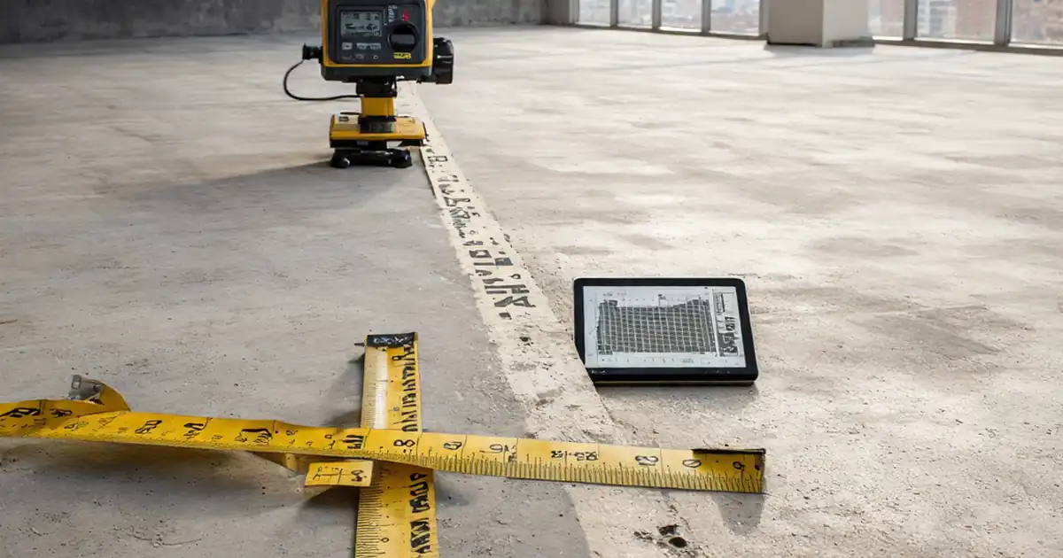
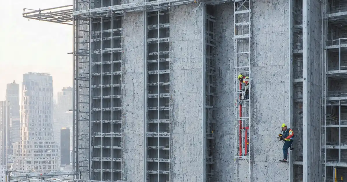
Review Façade Interface with Structural Frame & Edge Beam Geometry
Definition: Review façade interface with structural frame and edge beam geometry ensures accurate alignment, anchorage locations, and movement allowances for site engineers and façade coordinators.
- Verifies slab-edge lines, levels, and plumb within agreed tolerances.
- Confirms anchor coordinates, edge distances, and adjustment reserves before install.
- Assesses movement joints, camber, and deflection against façade capacity.
- Interactive, commentable checklist; export to PDF/Excel with QR code.
Review façade interface with structural frame and edge beam geometry is essential to prevent misalignment, rework, and weatherproofing failures at the building envelope. This checklist focuses on façade-to-structure coordination at slab edges, edge beams, and anchor zones, ensuring accurate setting-out, bracket fit-up, and movement accommodation. It addresses related tasks such as slab edge survey, edge beam alignment, bracket adjustment range confirmation, and verification of interstory drift and thermal allowances. The scope excludes façade panel fabrication quality, sealant application, and firestopping materials, but captures their controlling dimensions and interfaces. By confirming datums, tolerances, and buildability early, project teams reduce site cutting, drilling, and patch repairs while protecting design intent and warranty obligations. Use this tool to document measurements, photos, and approvals per approved project specifications and authority requirements, supporting transparent sign-offs and traceable decisions. Start interactive mode to tick, add comments with photos, and export as PDF/Excel via a secure QR code link for field sharing.
- Ensure façade datum control, slab-edge straightness, and anchor coordinates are verified before installation. This prevents bracket rework, uncontrolled drilling, and sealant joint creep, while confirming movement allowances and deflection compatibility with the façade system. All findings are captured with calibrated measurements, photos, and responsible sign-offs.
- Coordinate structural frame geometry with façade jointing strategy to maintain consistent reveals, drainage falls, and panel gaps. The process aligns survey control to primary benchmarks, validates camber and predicted deflection against adjustment ranges, and flags clashes with adjacent trades, minimizing costly program impacts and elevating build quality.
- Interactive online checklist with tick, comment, and export features secured by QR code.
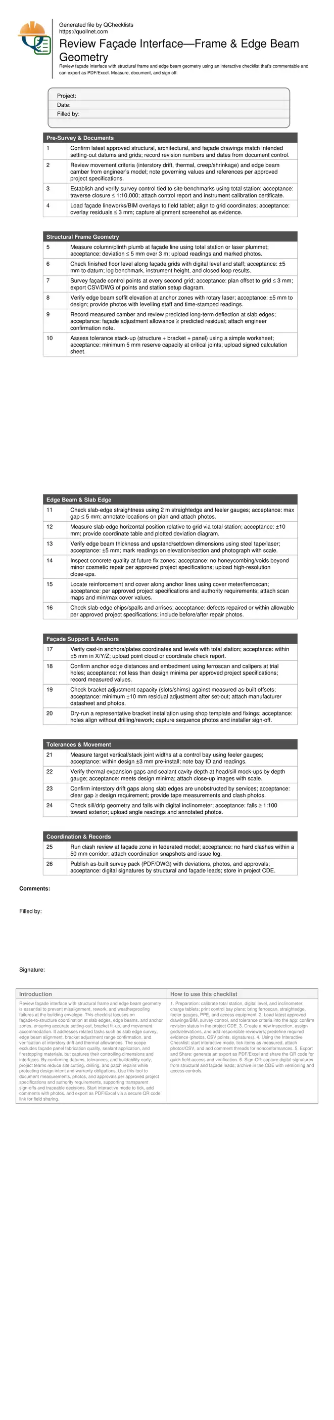
Pre-Survey & Documents
Structural Frame Geometry
Edge Beam & Slab Edge
Façade Support & Anchors
Tolerances & Movement
Coordination & Records
Why slab-edge and frame geometry drive façade success
Façade interface quality lives or dies on geometry. Slab edges that wander, beams out of level, or poorly placed anchors cascade into gapped mullions, uneven reveals, and water-management failures. This checklist concentrates on the transition between the structural frame and façade support—confirming datums, line-and-level, and bracket fit-up while respecting drift, thermal movement, and camber. The aim is practical risk control: lock in reliable control points, measure what matters, and document evidence clearly. When tolerances are verified before installation, teams avoid field drilling, hot works, and patching that jeopardize durability and warranties. Clear acceptance cues—like straightedge gaps, coordinate residuals, and adjustment reserves—translate design intent into buildable reality. Real jobsite examples include marking a control bay, proving joint widths with feeler gauges, and overlaying survey points on the façade grid to visualize deviations in seconds.
- Geometry errors multiply through panelized systems.
- Set control early; verify with calibrated instruments.
- Measurement plus photo evidence speeds approvals.
- Reserve adjustment capacity for real-world variance.
- Control bays de-risk full production roll-out.
Efficient survey workflow and acceptance cues
Start by aligning field devices to primary benchmarks, then import façade linework for immediate comparison. Use a total station for coordinates and a digital level for elevations; confirm closures to show survey integrity. Straightedge and feeler gauges quickly expose slab-edge waviness that destabilizes joint widths. Ferroscan identifies reinforcement conflicts before drilling, while bracket templates validate hole alignment without committing to permanent fixing. Acceptance cues must be unambiguous: numeric tolerances for line, level, and plumb; documentary proof such as CSV points, annotated photos, and marked-up drawings; and sign-offs from responsible parties. Always cross-check tolerance stack-up: structure, bracket, and panel allowances must still leave a small reserve, protecting aesthetics and watertightness when temperature swings or creep appear.
- Use total station for X/Y/Z; record closures.
- Digital level confirms elevations and falls.
- Straightedge tests expose local waviness fast.
- Ferroscan prevents costly reinforcement conflicts.
- Templates validate bracket fit-up preinstall.
Movement, buildability, and long-term performance
Edge beam camber, predicted long-term deflection, and interstory drift dictate how much adjustment a façade needs. If adjustment runs out, joints pinch, seals thin, and panes bind during seasonal cycles. Reviewing structural predictions against bracket slot lengths and shim strategies keeps reserves intact. Thermal gaps and sealant cavities must meet design minima, and services should never intrude into drift corridors. Water management relies on consistent sill falls and unobstructed drips, so measuring slopes is as critical as coordinates. Document decisions with signed calculations and photos; if any value relies on engineering judgment, record the reference and approval. The outcome is a façade that installs cleanly now and performs for decades without creeping misalignment.
- Match deflection to bracket adjustment capacity.
- Protect drift corridors from services.
- Confirm sealant cavity depth and width.
- Measure sill falls; ensure outward drainage.
- Record approvals for judgment-based decisions.
How to Use This Checklist On Site
- Preparation: calibrate total station, digital level, and inclinometer; charge tablets; print control bay plans; bring ferroscan, straightedge, feeler gauges, PPE, and access equipment.
- Load latest approved drawings/BIM, survey control, and tolerance criteria into the app; confirm revision status in the project CDE.
- Create a new inspection, assign grids/elevations, and add responsible reviewers; predefine required evidence (photos, CSV points, signatures).
- Using the Interactive Checklist: start interactive mode, tick items as measured, attach photos/CSV, and add comment threads for nonconformances.
- Export and Share: generate an export as PDF/Excel and share the QR code for quick field access and verification.
- Sign-Off: capture digital signatures from structural and façade leads; archive in the CDE with versioning and access controls.
Call to Action
- Start Checklist Tick off tasks, leave comments on items or the whole form, and export your completed report to PDF or Excel—with a built-in QR code for authenticity.
- Download Excel - Façade Interface & Edge Beam Geometry Review
- Download PDF - Façade Interface & Edge Beam Geometry Review
- View Image - Façade Interface & Edge Beam Geometry Review
Cite & Embed
“Façade Interface & Edge Beam Geometry Review by Quollnet”
with a link to
this source page.

FAQ
Question: What tolerances are typically acceptable at slab edges and façade datum lines?
Question: What if cast-in anchors or plates are out of position?
Question: When should the façade interface survey be carried out?
Question: How do we account for camber and long-term deflection in the façade?
Related Articles
Broader reading and guidance connected to this checklist topic.

Fidic Site Instruction Form – Free Download And Usage Tips


What Is a Snag List Or Punch List
Related Checklists
Keep the workflow moving with nearby templates chosen from similar checklist content.