
Method Statement: Fire Alarm Cable Installation Works (Routing, Segregation, Pulling, Identification, Pre-Termination Testing) – Method Statement
AI-assisted method statement with matching ITP, PDF download, and Excel export.
More than a static template
Unlike a downloadable Word or PDF template, this method statement is an AI-assisted editable starting point connected directly to a matching Inspection and Test Plan. Every section is structured, project-adaptable, and ready to export.
- AI-assisted drafting — Customize every section with AI for your specific project scope.
- Linked ITP — A matching inspection and test plan is generated alongside the method statement.
- Multiple export formats — Download as a formatted PDF or editable Excel spreadsheet.
- Editable starting point, not a final document — Review, verify, and adjust all content against your project requirements before use.
Static template vs. Quollnet workflow
| Feature | Static template | Quollnet |
|---|---|---|
| Project-specific content | Manual fill-in required | AI-assisted customization |
| Linked ITP | Separate document, no link | Matching ITP included |
| Export formats | Usually PDF only | PDF and Excel |
| Structured sections | Free-form layout | 13 standardized sections |
| Saved to your account | Local file only | Cloud-saved, reusable |
| Content accuracy | You verify everything | AI-assisted, you still verify |
| Cost | Often free but time-intensive | Free to customize and download |
What you can customize
When you save this method statement to your account, every section becomes editable. The following 13 sections are included:
- Scope — Defines the activity and its boundaries.
- References — Standards, specifications, and drawings.
- Responsibilities — Roles and accountabilities.
- Resources — Labour, plant, and equipment summary.
- Materials — Materials and compliance requirements.
- Equipment — Tools and equipment details.
- Prerequisites — Hold points and pre-conditions.
- Method sequence — Step-by-step construction sequence.
- Safety controls — HSE risk controls and PPE.
- Environmental controls — Environmental mitigation measures.
- QA/QC — Quality inspection and test requirements.
- ITP — Inspection and Test Plan table (has its own page).
- Attachments — Referenced drawings and documentation.
Why this method statement is used
This method statement is used to define and communicate the approved procedure for carrying out method statement: fire alarm cable installation works (routing, segregation, pulling, identification, pre-termination testing) on site. It ensures the work is planned in advance, the correct resources and controls are in place, and all personnel understand responsibilities, sequence, quality requirements, and safety controls before work begins. It aligns site execution with the documented scope and acceptance expectations.
Who uses this method statement
This method statement is used by contractors, site supervisors, project engineers, QA/QC engineers, HSE officers, consultants, and client representatives. It serves as a shared reference for planning, execution, supervision, inspection, and approval of the activity on site.
When it is prepared and submitted
The method statement is prepared before the work activity starts and submitted as part of the pre-construction documentation package for review and approval.
Who reviews or approves it
The method statement is usually submitted to the client representative, consultant, resident engineer, or project management consultant for review and approval before the work commences.
Important approval note
This method statement is an AI-assisted editable starting point, not a pre-approved document. Before use on any project, all content must be reviewed and approved by the relevant parties (superintendent, principal contractor, or client representative) in accordance with your contract and project quality plan.
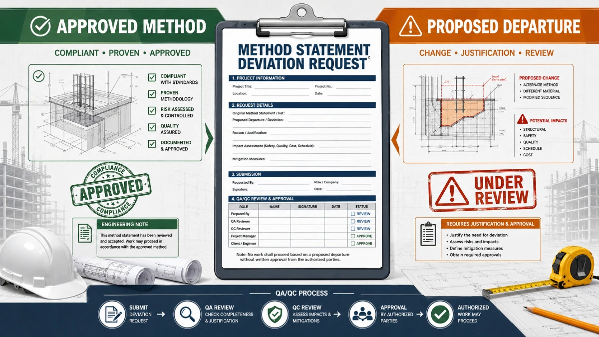
For example: if your specification requires a departure from a referenced standard, that departure must be documented and approved separately — this method statement will not capture that automatically. Always verify against your applicable drawings, specifications, and regulatory requirements.
Method statement content
Scope
Overview
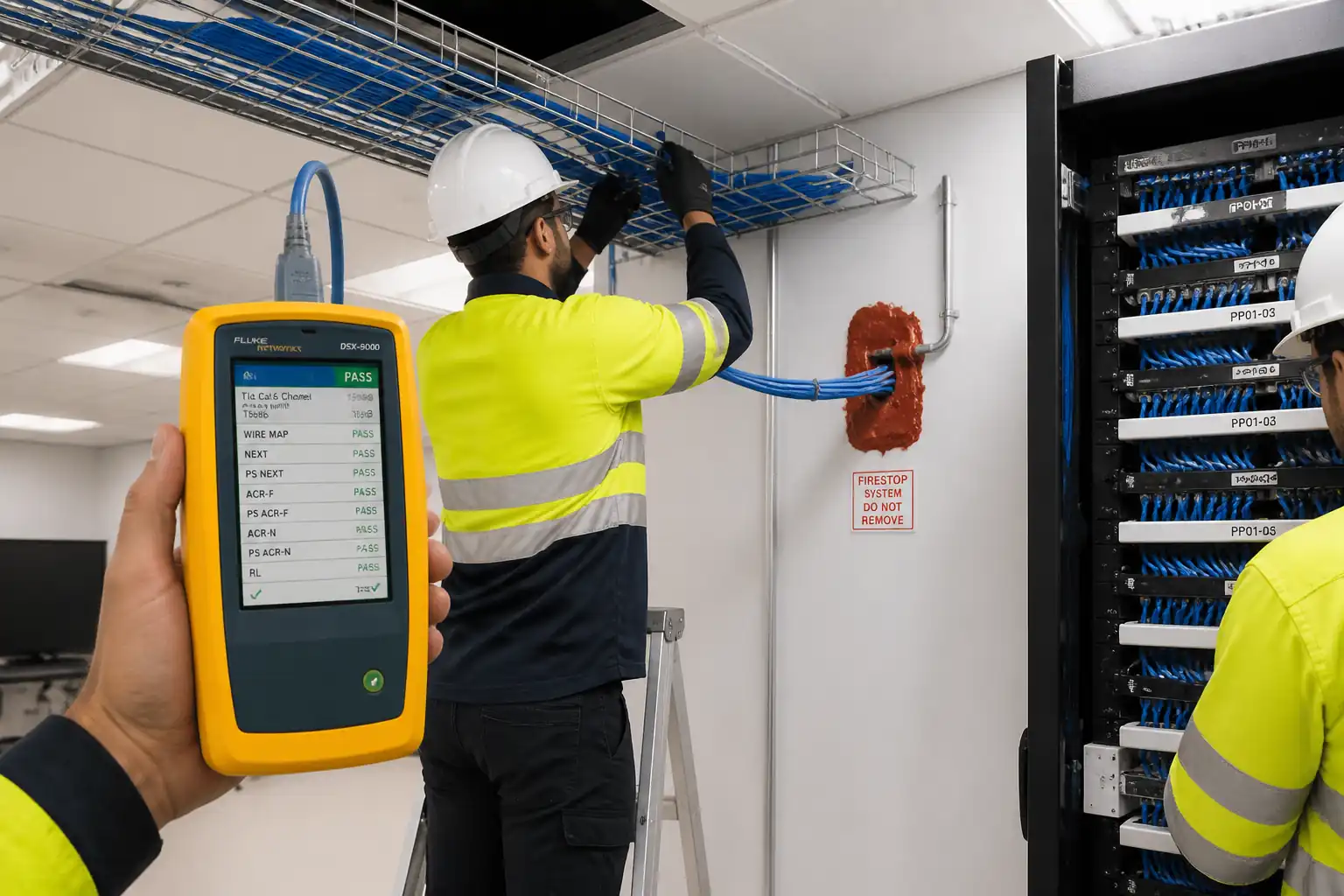
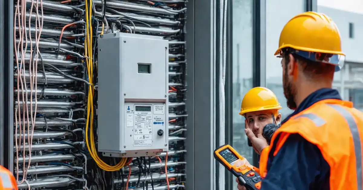
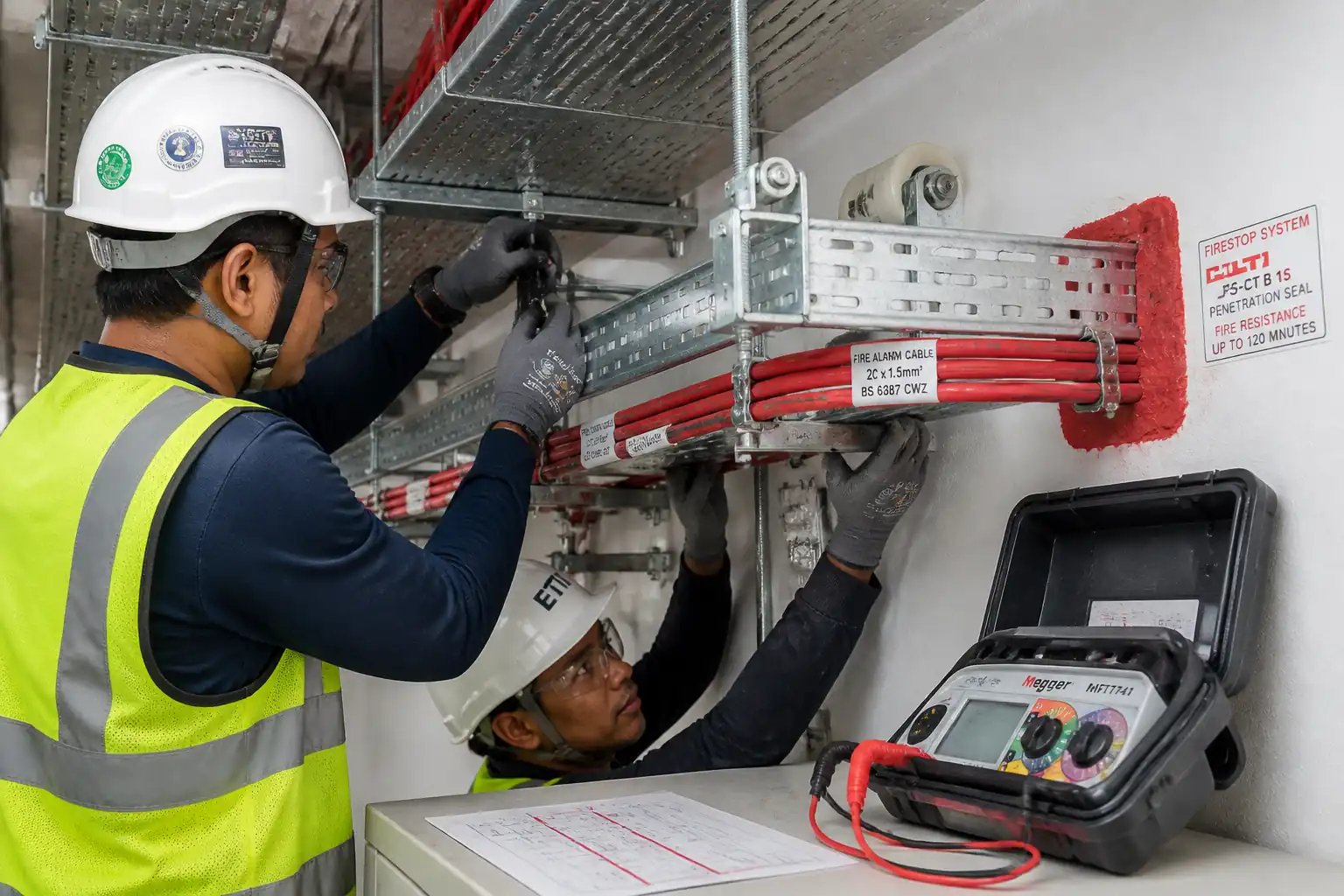
This method statement covers the supply, handling, installation, routing, segregation, dressing, identification, and pre-termination testing of fire alarm cabling (including fire-resistant cables such as MICC and soft-skin LSZH types) from control panels to field devices and interfaces. It includes containment verification, penetrations, temporary end protection, QA/QC inspections, and documentation prior to device/terminal connections.
Inclusions
- Verification of approved drawings, cable schedules, and material approvals (MARs).
- Inspection and preparation of cable containment (trays, ladders, conduits, trunking, risers).
- Routing and segregation from power and other services.
- Controlled cable pulling, dressing, cleating, and mechanical protection.
- Identification and labeling.
- Pre-termination tests: continuity and insulation resistance (IR) of circuits.
- Firestopping of penetrations (equal to barrier rating).
- QA/QC hold and witness points, records, and as-built markups.
Exclusions
- Device termination, panel terminations, cause-and-effect programming, and system commissioning (covered under separate method).
- Permanent energization and functional testing (covered under separate method).
References
| Document Type | Reference / Number | Revision | Notes |
|---|---|---|---|
| Standard | BS 5839-1: Fire detection and fire alarm systems for buildings – Design, installation, commissioning and maintenance [Verify governing edition per project] | Primary reference for UK/Eurocode-based projects; use NFPA 72 where specified. | |
| Standard | BS 7671 (IET Wiring Regulations) [Verify edition] | Cable routing, segregation, containment fill, and support requirements incl. non-combustible fixings in escape routes. | |
| Standard | NFPA 72: National Fire Alarm and Signaling Code [If specified] | Design/installation/testing reference for projects under NFPA regime. | |
| Standard | BS 7629-1 / BS 7846; EN 50200; IEC 60331; IEC 60332-1-2/-3 series | Fire-resistant cable performance (PH30/PH60/PH120), circuit integrity and flame propagation. | |
| Standard | ASTM E814 / UL 1479; EN 1366 series; ETA/ETAG for firestopping systems | Firestop systems for service penetrations – integrity and insulation ratings. | |
| Standard | ISO 9001, ISO 14001, ISO 45001 | Quality, environmental, and safety management frameworks. | |
| Project Document | Project Specifications, Approved Drawings, Cable Schedules, MARs | Governing requirements for materials, routes, and tests [Verify per project specifications]. |
Responsibilities
| Role | Responsibility | Name / Party |
|---|---|---|
| Project Manager | Overall execution, resources, interface with Client/Consultant, approvals. | Contractor |
| Site Engineer (Electrical) | Shop drawings/as-builts, setting out, technical supervision, RFI/TQ management. | Contractor |
| QA/QC Engineer | Inspections, ITP compliance, records, NCR management, calibration verification. | Contractor |
| HSE Officer | Task risk assessments, PTW, site surveillance, toolbox talks, incident reporting. | Contractor |
| Electrical Supervisor/Foreman | Daily work coordination, workforce allocation, workmanship control. | Contractor |
| Cable Pulling Team | Cable handling, pulling, dressing, fixing, labeling under supervision. | Contractor |
| Firestopping Specialist | Installation and inspection of firestopping systems and documentation. | Approved Subcontractor |
| Consultant/Engineer | Review/approval of inspections, compliance with specifications. | Engineer/Client Representative |
Resources
| Resource Type | Description | Quantity | Remarks |
|---|---|---|---|
| Personnel | 1 | ||
| Personnel | 1 | ||
| Personnel | 1 | ||
| Personnel | 1 | ||
| Personnel | 1 | ||
| Personnel | 4–8 |
Materials
| Material | Specification / Grade | Quantity | Remarks |
|---|---|---|---|
| Fire alarm cable (soft-skin) | 2C/1.5 mm² or as scheduled; red sheath; CPR class where applicable [Verify] | As per BOQ | |
| MICC fire-resistant cable | BS 6207/EN 60702-1; sheath colour red or per project [Verify] | As required | |
| Metallic cable cleats/clips/ties | Stainless/galvanized steel, fire-rated supports per BS 7671 Amd. 3 [Verify] | As required | |
| Cable tray/ladder/trunking/conduit | Hot-dip galvanized steel/aluminium; trunking with metallic dividers; IP rating per location [Verify] | As per drawings | |
| End caps/heat-shrink | LSZH where exposed; size to suit cable OD | As required | |
| Firestop sealants, wraps, pillows, mortars | Tested systems per EN 1366/UL 1479 with ETA/UL listings; same FR rating as barrier [Verify] | As required | |
| Labels/markers/sleeves | LSZH, engraved/printed; UV and heat resistant; English + local language if required [Verify] | As required |
Equipment
| Equipment | Capacity / Type | Quantity | Inspection Required |
|---|---|---|---|
| Cable drum jacks/stands | Rated > drum mass [Verify] | 1 set | Pre-use check; LOLER cert if lifted [Verify] |
| Dynamometer/tension gauge or in-line load cell | 0–500 N typical [Verify] | 1 | Calibration certificate valid |
| Cable rollers and bend radius guides | As required | Pre-use inspection | |
| Cable pulling accessories | As required | Pre-use check | |
| Test instruments | IR: 250/500 V DC selectable | 1 each/team | Calibration certificate valid |
| Ladders/Scaffolds/MEWPs | As required | Scaffold tag/MEWP inspection; operator license [Verify] | |
| Fixing tools | As required | PAT/inspection records [Verify] | |
| Label printer | 1 | Consumables per spec |
Prerequisites
- Approved shop drawings, cable schedules, single-line/loop diagrams, and MARs for all materials.
- ITP and this Method Statement approved by the Engineer.
- Permits to Work (PTW) including hot work (if drilling/cutting generates heat/sparks) and work-at-height permits [Verify per project HSE plan and local regulations].
- Coordination drawings (MEP + architectural/structural) and route clearance confirmed via latest BIM/combined services drawings.
- Containment installed to the required fire rating where applicable; supports inspected and accepted.
- Calibration certificates for test instruments (IR tester, multimeter, dynamometer) valid.
- Toolbox Talk completed: manual handling of drums, work at height, electrical isolation/lockout, silica dust control, firestopping.
- Access, lighting, and housekeeping in work areas adequate; ceiling grids open as needed.
- Power isolations confirmed or barriers in place around live equipment; confirm absence of energized conductors in work area where required.
- Firestop system submittals approved with tested details for each penetration type and construction.
- Materials delivered in good condition, with certificates of compliance. Drums inspected and stored upright on firm level ground.
Method Sequence
| Step | Activity | Description | Responsibility | Inspection / Hold Point |
|---|---|---|---|---|
| 1 | Document and site verification | Verify approved drawings, cable schedule, routes, and penetration details. Walk down workfront and mark routes, supports, and pulling points. | Site Engineer/Supervisor | Pre-start check |
| 2 | Containment inspection (prior to cable) | Inspect trays, ladders, trunking, conduits, risers for alignment, fixity, earth bonding (if required), protective grommets at entries, and cleanliness. | QA/QC + Engineer | Hold Point (H) |
| 3 | Segregation and barriers | Install metallic dividers or maintain separation from LV power and other services. Mark crossing points. | Supervisor | Witness (W) |
| 4 | Cable drum handling and setup | Position drum on jacks; pay-off in direction of arrow to avoid reverse lay. Route rollers/bend guides along path. | Supervisor + Team | Surveillance |
| 5 | Cable pulling (controlled) | Pull using draw wire or socks; use rollers at 1.5–2.0 m spacing and at changes in direction. Monitor tension with dynamometer. | Supervisor + Team | Witness (W) |
| 6 | Dressing, cleating and termination preparation | Dress cables neatly, avoid twists; install metallic clips/cleats. Fit end caps/heat-shrink to free ends to keep dry and clean. | Team | Surveillance |
| 7 | Containment fill and route verification | Confirm fill factors and spare capacity. Verify no sharp edges; install edge protection/bushings. | QA/QC + Engineer | Witness (W) |
| 8 | Identification and labeling | Install permanent labels at both ends, at every 10 m along route (or at each accessible section), at each floor in risers, and before/after penetrations. | Team | Surveillance |
| 9 | Penetrations and firestopping | Core/cut penetrations as per approved details. After cable installation, install tested firestop systems (sealant/wrap/pillow/mortar) to match barrier FR rating. | Firestopping Specialist | Hold Point (H) before close-up |
| 10 | Continuity testing (pre-termination) | Test cores end-to-end continuity with devices disconnected. Check for open/short/crossed cores. Record loop resistance where required. | QA/QC + Engineer | Witness (W) |
| 11 | Insulation resistance (IR) testing (pre-termination) | With all equipment disconnected, test between conductors and to earth using 500 V DC for new cables (or 250 V DC where specified) for 1 minute. | QA/QC + Engineer | Witness (W) |
| 12 | Temporary protection and ceiling/closure release | Cap and secure cable ends. Offer area for inspection prior to ceiling closure or boxing-in. | Supervisor/QAQC | Hold Point (H) |
| 13 | Documentation and handover for termination | Compile inspection records, test results, firestop register, material certificates, calibration records, and as-built markups; hand over to termination team. | QA/QC Engineer | Review |
Safety Controls
Task-specific HSE Controls
- Hazard: Work at height on ladders/scaffolds/MEWPs
- Likely consequence: Falls causing serious injury or fatality.
- Engineering/procedural control: Use tagged mobile towers or MEWPs for sustained work; maintain 3-point contact on ladders for short-duration tasks only; install edge protection; exclude work under suspended loads.
- Required PPE: Helmets with chin strap, full-body harness with lanyard on MEWPs, non-slip safety footwear.
- Collective preventive measure: Guardrails/toeboards on platforms; spotter for MEWP.
-
Inspection/permit/supervision: Work-at-Height permit; pre-use inspection of ladders/MEWPs; certified operators [Verify per project HSE plan and local regulations].
-
Hazard: Manual handling of cable drums and heavy reels
- Likely consequence: Musculoskeletal injury, crush injuries.
- Engineering/procedural control: Use drum jacks, pallet jacks, or forklifts; team lifts; keep hands clear; position drums on level, chocked surfaces.
- Required PPE: Safety gloves, steel-toe boots.
- Collective preventive measure: Mechanical handling plan and exclusion zones.
-
Inspection/permit/supervision: Equipment inspection; banksman during moves.
-
Hazard: Contact with live electrical services during drilling/pulling
- Likely consequence: Electric shock, arc flash.
- Engineering/procedural control: Service detection/scan; lockout-tagout (LOTO) for nearby circuits where feasible; maintain safe distances; use insulated tools.
- Required PPE: Dielectric gloves where required, arc-rated clothing if exposure risk exists.
- Collective preventive measure: Permit to Work with isolation; barriers and signage.
-
Inspection/permit/supervision: Electrical PTW/LOTO records; supervisor verification [Verify per project HSE plan and local regulations].
-
Hazard: Use of power tools (drilling/anchoring)
- Likely consequence: Eye injuries, cuts, vibration-related injuries.
- Engineering/procedural control: Use guards, correct drill bits, torque control; dust extraction on drills.
- Required PPE: Safety glasses/face shield, cut-resistant gloves, hearing protection.
- Collective preventive measure: Task-specific JSA and equipment PAT/testing.
-
Inspection/permit/supervision: Hot work permit if sparks; tool inspection logs.
-
Hazard: Cable pulling pinch/crush points
- Likely consequence: Finger/hand injuries.
- Engineering/procedural control: Use rollers and guides; establish communication signals; keep hands off the line; use pulling socks correctly.
- Required PPE: Tight-fitting gloves, eye protection.
- Collective preventive measure: Exclusion zone along pulling path.
-
Inspection/permit/supervision: Supervisor to brief crew; monitor pulling force with dynamometer.
-
Hazard: Dust and silica during coring/cutting
- Likely consequence: Respiratory irritation, silicosis (long-term).
- Engineering/procedural control: Wet coring or on-tool extraction; local exhaust ventilation; minimize dry cutting.
- Required PPE: FFP3/P100 respirator, goggles.
- Collective preventive measure: Dust curtains/containment; housekeeping.
-
Inspection/permit/supervision: Hot work/dust control permit as applicable.
-
Hazard: Firestopping chemical exposure (sealants/mortars)
- Likely consequence: Skin/eye irritation, chemical burns.
- Engineering/procedural control: Follow SDS; mix/apply per manufacturer; provide wash stations.
- Required PPE: Chemical-resistant gloves, goggles, long sleeves.
- Collective preventive measure: Ventilation; spill kits.
-
Inspection/permit/supervision: SDS on site; COSHH assessment [Verify per local regulations].
-
Hazard: Sharp edges on metal containment
- Likely consequence: Lacerations.
- Engineering/procedural control: Deburr edges; fit grommets and edge protectors at entries.
- Required PPE: Cut-resistant gloves, sleeves as needed.
- Collective preventive measure: Tooling for deburring assigned; periodic checks.
-
Inspection/permit/supervision: QA/QC inspections of entries.
-
Hazard: Noise from drilling/coring
- Likely consequence: Hearing damage.
- Engineering/procedural control: Select low-noise methods; limit exposure time.
- Required PPE: Hearing protection (SNR/NRR suitable).
- Collective preventive measure: Noise monitoring and signage in high-noise areas.
-
Inspection/permit/supervision: HSE noise assessment records.
-
Hazard: Housekeeping and trip hazards (cables/rollers across walkways)
- Likely consequence: Slips, trips, falls.
- Engineering/procedural control: Cable management mats; tidy as you go; remove waste promptly.
- Required PPE: Safety footwear.
- Collective preventive measure: Segregated walkways; barriers and signs.
- Inspection/permit/supervision: Daily inspections by Supervisor.
Environmental Controls
- Waste segregation: Collect cable offcuts, drum packaging, and metal scrap separately; return wooden drums to supplier where possible; recycle metals and cardboard.
- Dust control: Use wet coring or on-tool extraction; damp-wipe surfaces; avoid uncontrolled dry cutting. Maintain dust curtains where near sensitive areas.
- Noise: Schedule drilling during permitted hours; use acoustic barriers where necessary; comply with project noise limits [Verify per local regulations].
- VOCs/chemicals: Select low-VOC sealants where approved; keep containers closed; spill kits available; store chemicals in bunded trays.
- Energy and emissions: Use electric MEWPs where feasible; switch off idle equipment; consolidate deliveries.
- Water management: Contain and properly dispose of slurry from wet coring; prevent discharge to drains without treatment.
- Protection of finishes: Use floor protection and cable rollers with non-marking bases; repair any damage promptly.
- Environmental incidents: Report and record spills; remediate per project EMP; maintain SDS and COSHH assessments on site.
QA/QC
Quality Controls
- Materials: Verify against MARs; check cable type, rating (PH rating, LSZH), sheath color, conductor CSA, and manufacturer certificates. Record batch/lot numbers.
- Tools and instruments: Calibration certificates current for IR tester, multimeter, and dynamometer. Keep copies in turnover file.
- Workmanship checks: Containment alignment, fixity, edge protection; segregation distances; cleat spacings; bend radius compliance; absence of sheath damage.
- Fill and capacity: Verify trunking fill ≤45% CSA and tray spare ≥25% [Verify per project specs].
- Firestopping: Only tested systems; install per approved detail; record system ID and location in the firestop register.
- Testing: Perform continuity and IR tests prior to any terminations. Repeat after any major rework.
- Records: Use standardized checklists and test sheets. Photographic evidence before and after firestopping.
Acceptance Criteria (benchmarks unless project-specified)
- Segregation: ≥300 mm from LV power or continuous metallic divider; crossings at 90°.
- Bend radius: Soft-skin fire-resistant ≥8–12 × OD; MICC ≥6 × OD [Verify per manufacturer].
- Pulling force: ≤50 N/mm² of total copper CSA.
- Support spacing: Horizontal 400–600 mm cleats; vertical 300 mm; tray supports ≤1200 mm (typical) [Verify].
- IR: ≥200 MΩ at 500 V DC for 1 minute on new, disconnected cables [Verify per project].
- Continuity: No opens/shorts/crosses; loop resistance within design allowance [Verify].
- Firestopping: Rating equal to or greater than barrier; tagged and recorded.
Documentation
- Inspection Requests (IRs), ITP checklists, pull logs, test sheets (continuity/IR), calibration certificates, MARs, delivery dockets, as-built/redline drawings, firestop register, NCR/CAR (if any).
Attachments
- Approved shop drawings and cable schedules.
- Manufacturer data sheets for cables, cleats, and firestop systems.
- Material submittal approvals (MARs) and certificates of conformity.
- Calibration certificates for test instruments and dynamometer.
- Inspection forms: Containment Pre-Install, Segregation, Pull Log, Label Register.
- Test sheets: Continuity and IR (pre-termination).
- Firestop register with system IDs, locations, photos, and approvals.
- Risk Assessment/Method Statement (RAMS), PTW copies, toolbox talk records.
- As-built/redline drawings reflecting final routes and labels.
This content is a read-only public reference. Download or customize to get an editable version.
ITP preview
The first inspection activities from the linked ITP for Method Statement: Fire Alarm Cable Installation Works (Routing, Segregation, Pulling, Identification, Pre-Termination Testing):
| Activity | Inspection / Test | Acceptance Criteria | Responsibility | Record |
|---|---|---|---|---|
| Material receipt and verification | Check cable type, rating, certificates, and condition; verify accessories and firestop materials. | Conforms to MAR and specs; no damage; certificates available. | QA/QC Engineer / Storekeeper | Material inspection report; delivery notes; certificates |
| Containment installation inspection (pre-cable) | Visual alignment; support spacing; earthing bonds; edge protection. | Supports within specified spacing; fixings torqued; grommets/edge protectors installed. | QA/QC + Engineer | IR; photos; torque records (sample) |
| Segregation verification | Measure separation; verify metallic dividers in trunking. | ≥300 mm separation from LV power or continuous metallic divider; 90° crossings. | QA/QC | Segregation checklist; IR |
Showing 3 of 12 inspection activities. View full ITP →
Related Inspection and Test Plan
An Inspection and Test Plan (ITP) is available for Method Statement: Fire Alarm Cable Installation Works (Routing, Segregation, Pulling, Identification, Pre-Termination Testing). The ITP defines the inspection activities, acceptance criteria, hold and witness points, responsible parties, and records required to verify the work described in this method statement.
View the Method Statement: Fire Alarm Cable Installation Works (Routing, Segregation, Pulling, Identification, Pre-Termination Testing) ITP →Frequently asked questions
Continue with related Quollnet resources connected to this method statement.