
Inspection and Test Plan for Method Statement – Horizontal Data Cabling Installation (Office Floors)
AI-assisted inspection and test plan connected to a method statement, with PDF and Excel export.
More than a static template
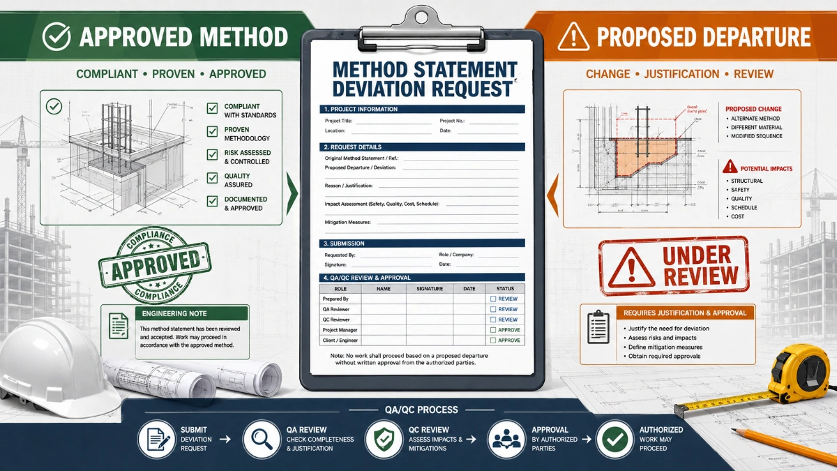
Unlike a downloadable Word or PDF template, this ITP is an AI-assisted editable starting point directly connected to its method statement. Every inspection activity, hold point, and acceptance criterion is structured and ready to adapt to your project.
- AI-assisted customization — Tailor inspection activities and acceptance criteria to your specific project scope.
- Linked method statement — This ITP is connected to the corresponding method statement describing the work sequence.
- Multiple export formats — Download as a formatted PDF or editable Excel spreadsheet.
- Editable starting point, not a final document — Review and verify all content against your project specifications and standards before use.
What you can customize
When you save this ITP to your account, every inspection row becomes editable. You can add, remove, or modify:
- Inspection activity — Description of what is being inspected.
- Inspection type — Hold point (H), Witness point (W), Review (R), or Monitor (M).
- Responsibility — Contractor, subcontractor, engineer, or client.
- Frequency — How often the inspection occurs.
- Acceptance criteria — Referenced standard or specification requirement.
- Records — Forms, test reports, or checklists required as evidence.
Why this ITP is used
To ensure each installation step is inspected and tested against applicable standards and project requirements before proceeding.
Who uses this inspection and test plan
Contractor site teams, QA/QC engineers, consultants/clients, and commissioning agents.
When this ITP is prepared and submitted
From material delivery through installation, testing, firestopping, documentation, and final handover.
Who receives or approves this ITP
Client/Consultant for review and approval prior to commencement.
Inspection scope
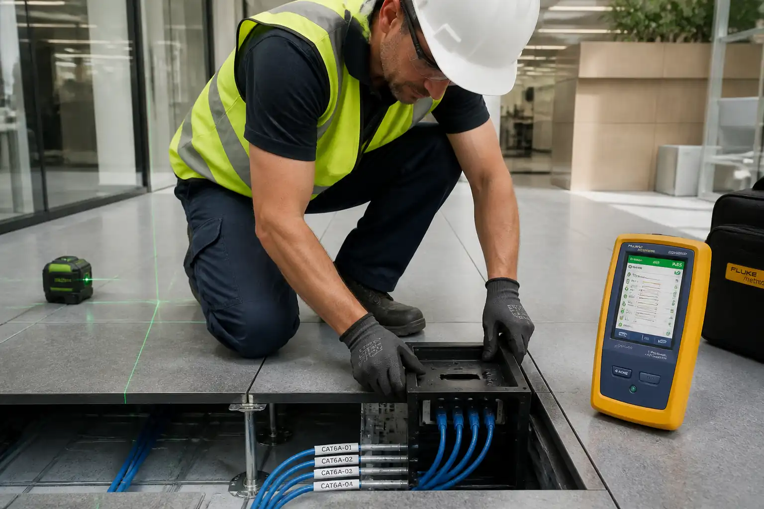
Materials verification, pathway readiness, pulling quality, terminations, labeling, firestopping, field certification testing, and documentation completeness.
Typical hold, witness, and review points
HP-1 Pre-install walkdown; HP-2 Firestopping before concealment; HP-3 As-built package before handover; WP-1 Initial cable pulls; WP-2 Patch panel termination; WP-3 Field certification testing.
Typical inspection records
MIRs, WIRs, checklists, calibration certificates, firestop logs, as-built drawings, cable schedules, native tester files, and approval transmittals.
Important approval note
This ITP is an AI-assisted editable starting point, not a pre-approved document. Before use on any project, all inspection activities, hold points, and acceptance criteria must be reviewed and approved by the relevant parties (superintendent, principal contractor, or client representative) in accordance with your contract and project quality plan.
Always verify acceptance criteria against your applicable drawings, specifications, and regulatory requirements. Hold points must be confirmed with the relevant authority before work proceeds past that point.
Inspection and test plan
| Activity | Inspection / Test | Acceptance Criteria | Responsibility | Record |
|---|---|---|---|---|
| Material delivery and MIR | Check cable drums, passive components, certificates | Materials match approved submittals; damage-free; certificates available | QA/QC Engineer / Consultant | MIR, photos |
| Pre-install walkdown (HP-1) | Verify routes, tray condition, fill limits, separations | Routes clear; separations achievable; trays bonded; supports per spec | Site Engineer / Consultant | Walkdown checklist, WIR approval |
| Containment preparation | Edge protection, bonding continuity, cleanliness | No sharp edges; earth continuity verified; area clean | Site Engineer / QA/QC | Inspection report |
| Cable pulling (WP-1) | Monitor tension, radii, lubricant compatibility, pathway fill | No jacket damage; radii maintained; fill within limits | Supervisor / Consultant | WIR, photos |
| Outlet termination | Check pinout per 568A/568B; untwist limits; service loop | Correct pinout; untwist within limits; neat installation | Supervisor / QA/QC | In-process checklist |
| Patch panel termination (WP-2) | Termination quality; shield continuity (if applicable); bonding | Correct pinout; bonds secure; no cable weight on jacks | Supervisor / Consultant | WIR, photos |
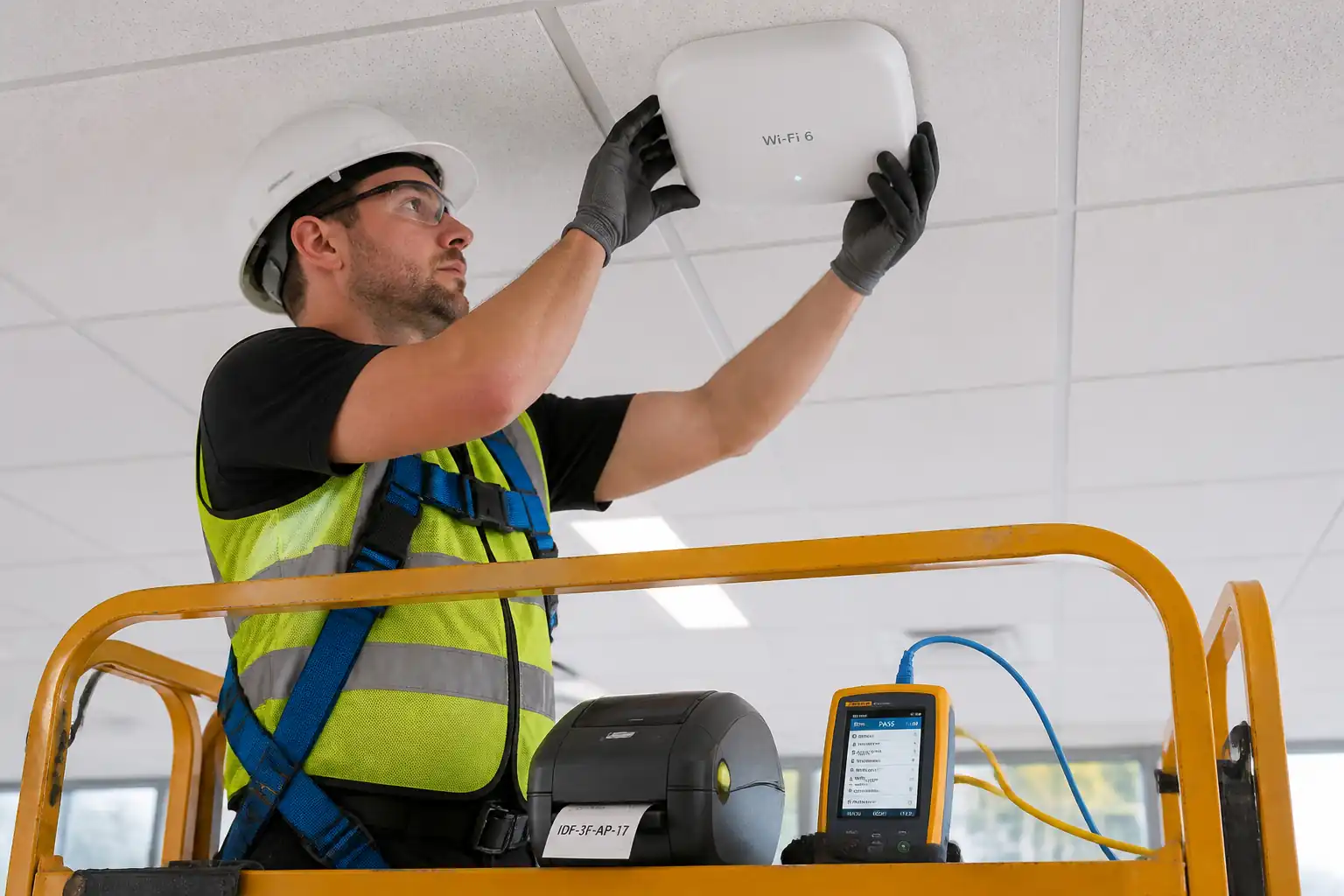
| Labeling and administration | Audit 10% sampling or as specified | Identifiers per TIA-606-C; end-to-end traceability | QA/QC Engineer | Label register, audit sheet |
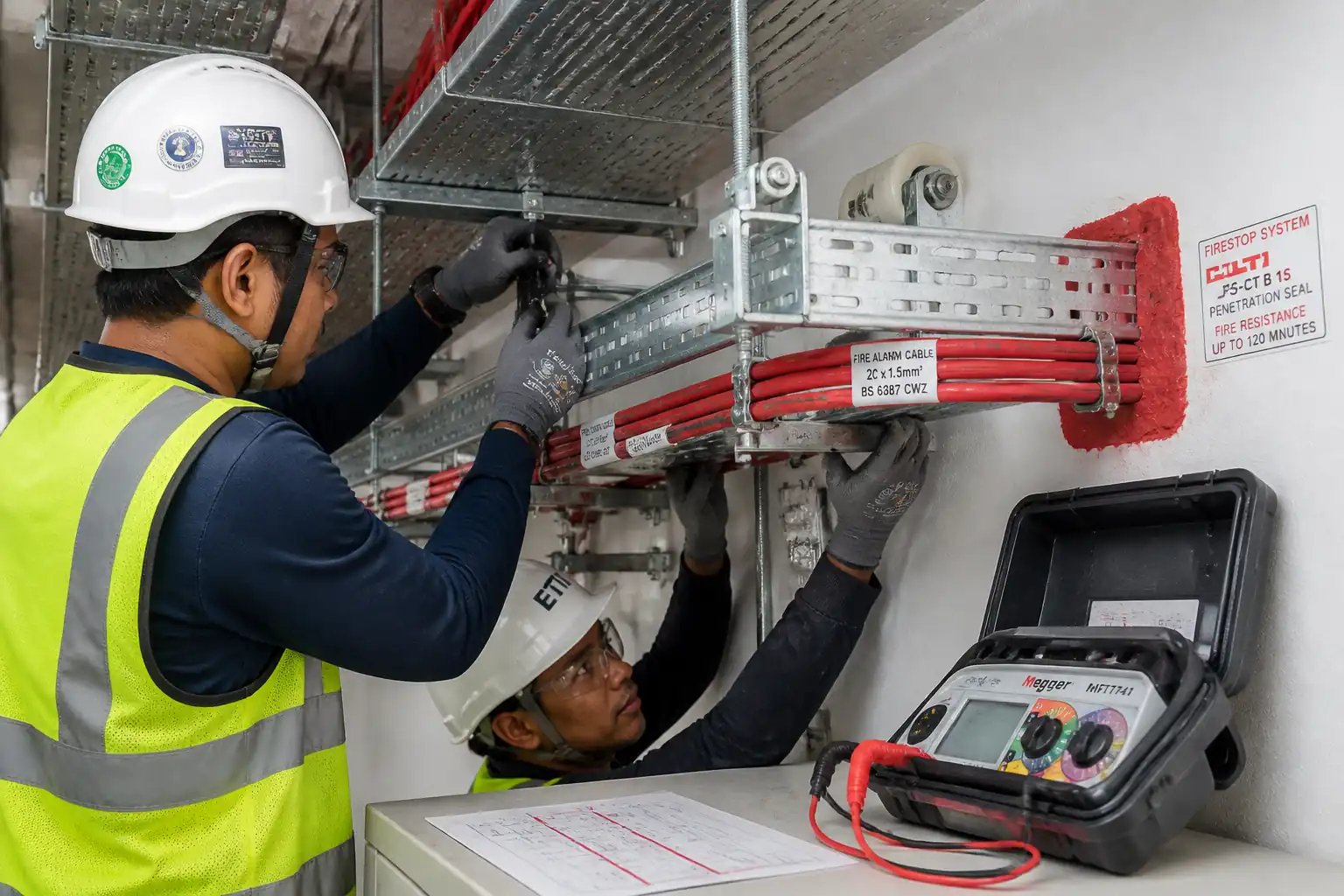
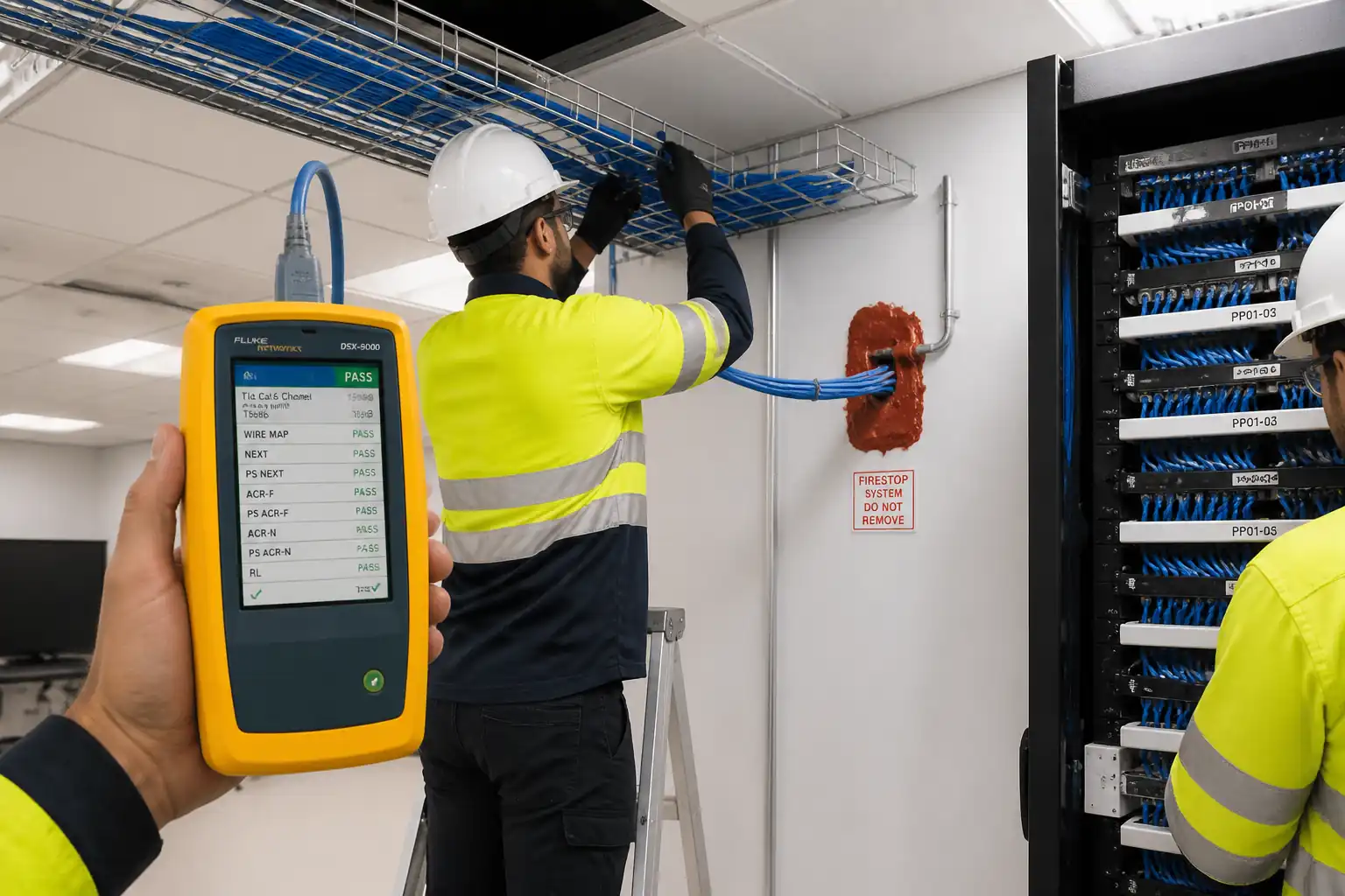
| Firestopping (HP-2) | Verify tested system ID, annular space, tag | Installed per listed system; neat, continuous seal; tagged | Firestop Installer / Consultant | Firestop log, WIR |
| Field certification testing (WP-3) | Fluke DSX PL/Channel test to TIA-568.2-D limits | PASS on wiremap, length, IL, NEXT/PSNEXT, ACR-F/PSACR-F, RL, delay, skew | Tester / QA/QC / Consultant | Native files (.flw), PDF summary, tester calibration cert |
| As-built documentation (HP-3) | Cross-check drawings, schedules, and test reports | 100% links documented; IDs consistent; records complete | QA/QC / Consultant | As-built set, transmittal |
| Final inspection and handover | Handover inspection, sample re-checks | All NCRs closed; approvals obtained | PM / Client | Completion certificate |
This table is a read-only public reference. Download the PDF or Excel version, or customize this ITP to edit it for your project.
Frequently asked questions
Related method statement
This Inspection and Test Plan is associated with the Method Statement – Horizontal Data Cabling Installation (Office Floors) method statement, which describes the step-by-step construction sequence, resources, materials, equipment, safety controls, and environmental controls for this activity.
View the Method Statement – Horizontal Data Cabling Installation (Office Floors) method statement →Continue with related inspection, method statement, article, and checklist resources.