Method Statement – Wireless Access Point (WAP) Installation and Commissioning – Method Statement
AI-assisted method statement with matching ITP, PDF download, and Excel export.
More than a static template
Unlike a downloadable Word or PDF template, this method statement is an AI-assisted editable starting point connected directly to a matching Inspection and Test Plan. Every section is structured, project-adaptable, and ready to export.
- AI-assisted drafting — Customize every section with AI for your specific project scope.
- Linked ITP — A matching inspection and test plan is generated alongside the method statement.
- Multiple export formats — Download as a formatted PDF or editable Excel spreadsheet.
- Editable starting point, not a final document — Review, verify, and adjust all content against your project requirements before use.
Static template vs. Quollnet workflow
| Feature | Static template | Quollnet |
|---|---|---|
| Project-specific content | Manual fill-in required | AI-assisted customization |
| Linked ITP | Separate document, no link | Matching ITP included |
| Export formats | Usually PDF only | PDF and Excel |
| Structured sections | Free-form layout | 13 standardized sections |
| Saved to your account | Local file only | Cloud-saved, reusable |
| Content accuracy | You verify everything | AI-assisted, you still verify |
| Cost | Often free but time-intensive | Free to customize and download |
What you can customize
When you save this method statement to your account, every section becomes editable. The following 13 sections are included:
- Scope — Defines the activity and its boundaries.
- References — Standards, specifications, and drawings.
- Responsibilities — Roles and accountabilities.
- Resources — Labour, plant, and equipment summary.
- Materials — Materials and compliance requirements.
- Equipment — Tools and equipment details.
- Prerequisites — Hold points and pre-conditions.
- Method sequence — Step-by-step construction sequence.
- Safety controls — HSE risk controls and PPE.
- Environmental controls — Environmental mitigation measures.
- QA/QC — Quality inspection and test requirements.
- ITP — Inspection and Test Plan table (has its own page).
- Attachments — Referenced drawings and documentation.
Why this method statement is used
This method statement is used to define and communicate the approved procedure for carrying out method statement – wireless access point (wap) installation and commissioning on site. It ensures the work is planned in advance, the correct resources and controls are in place, and all personnel understand responsibilities, sequence, quality requirements, and safety controls before work begins. It aligns site execution with the documented scope and acceptance expectations.
Who uses this method statement
This method statement is used by contractors, site supervisors, project engineers, QA/QC engineers, HSE officers, consultants, and client representatives. It serves as a shared reference for planning, execution, supervision, inspection, and approval of the activity on site.
When it is prepared and submitted
The method statement is prepared before the work activity starts and submitted as part of the pre-construction documentation package for review and approval.
Who reviews or approves it
The method statement is usually submitted to the client representative, consultant, resident engineer, or project management consultant for review and approval before the work commences.
Important approval note
This method statement is an AI-assisted editable starting point, not a pre-approved document. Before use on any project, all content must be reviewed and approved by the relevant parties (superintendent, principal contractor, or client representative) in accordance with your contract and project quality plan.
For example: if your specification requires a departure from a referenced standard, that departure must be documented and approved separately — this method statement will not capture that automatically. Always verify against your applicable drawings, specifications, and regulatory requirements.
Method statement content
Scope
Overview
This method statement covers the end-to-end installation and commissioning of wireless access points (WAPs) within a building, including:
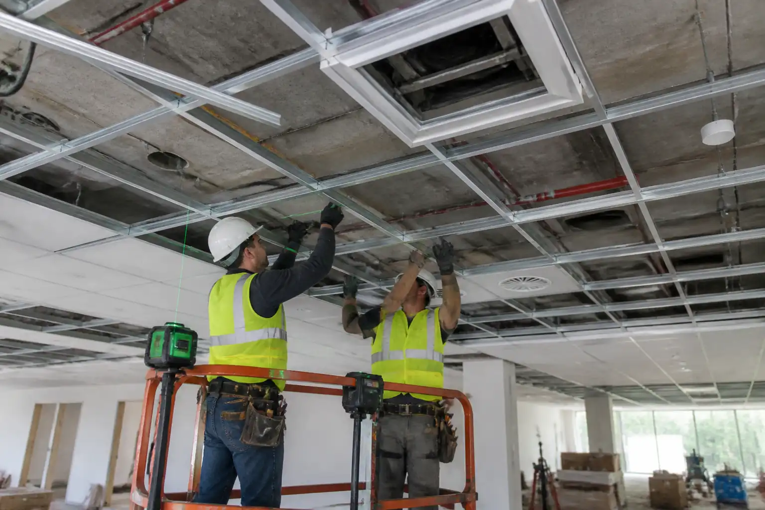
- Ceiling coordination and layout verification against approved reflected ceiling plans (RCP) and RF design.
- Data outlet preparation and structured cabling terminations at the telecommunications room (TR) and consolidation points, where applicable.
- Physical mounting of WAPs and associated brackets, back boxes, and fixings suitable for ceiling type.
- Labeling per TIA-606-C and asset tagging.
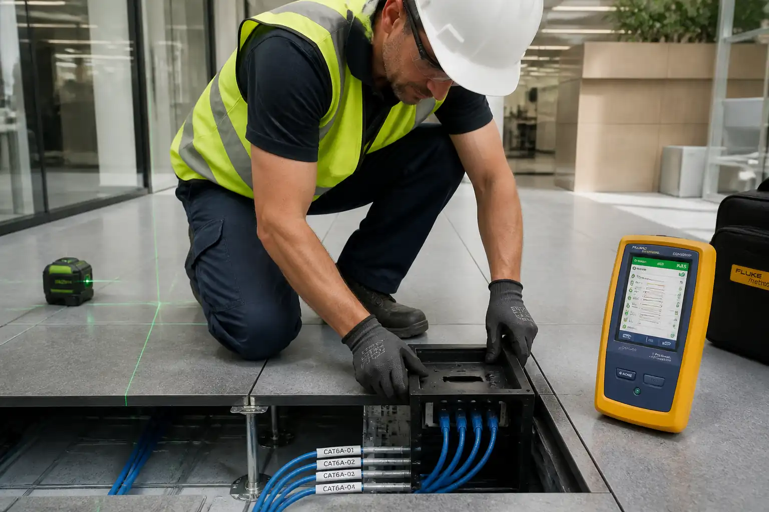
- Power-over-Ethernet (PoE) negotiation and electrical verification.
- Signal coverage verification via RF survey and system performance testing.
- Integration with the wired network and IT controller, configuration validation, and burn-in tests.
- Documentation, as-built updates, O&M submissions, and final inspection for handover.
Work excludes active IT configuration beyond site support (controller programming is by IT), backbone switching installation except PoE port allocation, and civil works unrelated to AP fixing or penetrations.
References
| Document Type | Reference / Number | Revision | Notes |
|---|---|---|---|
| Standard | IEEE 802.11 | Latest [Verify per project] | |
| Standard | ISO/IEC 11801 series | Latest [Verify per project] | |
| Standard | ANSI/TIA-568.2-D | Current [Verify per project] | |
| Standard | ANSI/TIA-606-C | Current [Verify per project] | |
| Standard | IEEE 802.3af/at/bt | Current [Verify per project] | |
| Code | IEC 60364 / NFPA 70 (NEC) / BS 7671 | Latest applicable [Verify per jurisdiction] | |
| Standard | ASTM E814 / UL 1479 / EN 1366-3 | Current [Verify per project] | |
| Standard | ANSI/TIA-569-D | Current [Verify per project] | |
| Standard | IEC 61935-1 / TIA Level 2G (Cat 6A) | Current [Verify per project] | |
| Standard | ISO 45001 | Latest [Verify per project HSE plan] |
Responsibilities
| Role | Responsibility | Name / Party |
|---|---|---|
| PM | Ensure approved drawings/specs and materials available; risk controls implemented | Contractor |
| Supervisor | Coordinate with ceilings, MEP; ensure workmanship and test compliance | Contractor |
| QA/QC | Witness/verify tests; maintain ITP and MDR | Contractor |
| HSE | Toolbox talks; permits; inspections of access/MEWP/ladders/chemicals | Contractor |
| IT | Provide AP configs, DHCP/DNS, RADIUS/AAA; participate in coverage validation | Client/IT |
| Vendor | Advise mounting, environment limits, firmware; attend critical tests | Manufacturer |
| CxA | Witness ITP hold points; review test results | Third Party |
Resources
| Resource Type | Description | Quantity | Remarks |
|---|---|---|---|
| Labor | Structured cabling and AP mounting | 2–4 per area [Verify per project] | |
| Labor | Operate scissor lift or mobile scaffold for high ceilings | As required | |
| Labor | Cable certification, PoE and RF testing | 1–2 |
Materials
| Material | Specification / Grade | Quantity | Remarks |
|---|---|---|---|
| AP | Wi‑Fi 5/6, PoE Class 3–6 [Verify] | As per BOQ | |
| Cable/Connectivity | Cat6/Cat6A [Verify] | Per drawings | |
| Fixings | Galvanized/SS as environment requires | ||
| Firestop | As approved | ||
| Labels | UV/heat resistant where required |
Equipment
| Equipment | Capacity / Type | Quantity | Inspection Required |
|---|---|---|---|
| DSX-8000 or equivalent | 1–2 | ||
| 1 | |||
| 1 | |||
| As required | |||
| 1–2 |
Prerequisites
Approvals and Coordination
- Approved shop drawings: RF design/heatmaps, RCPs, single-line diagrams, labeling scheme, schedules.
- BIM/coordination: Clash-free locations against MEP/architectural. RFI closures for any deviations.
- Permits: Work at height, hot works (if drilling through fire barriers), ceiling access permits [Verify per project HSE plan].
Site Readiness
- Ceilings installed and grid leveled; ceiling tiles/backing boards available. Above-ceiling area clean and accessible.
- TR/switch rooms energized; PoE switches installed or available test PSE; network VLANs and port configs agreed.
- Pathways (trays/conduits) complete, labeled, and free of sharp edges; penetrations formed or locations agreed.
Survey and Setting Out
- Confirm AP coordinates from RF plan onto RCP using control points. Mark on site with laser/measure.
- Typical location tolerances: horizontal ±100 mm from design; vertical height as per ceiling datum; maintain clearances:
- ≥1.0 m from large metal surfaces/ducts; ≥0.5 m from air diffusers/returns; avoid mounting directly below chilled beams [Verify per vendor/RF engineer].
- Keep AP underside flush with ceiling plane; avoid recessed wells unless vendor kit provided.
Materials and Tools
- Approved AP models and brackets available; fixings compatible with substrate.
- Calibrations in date for testers and analyzers.
HSE
- Task-specific risk assessment and toolbox talk completed; rescue plan for MEWP/scaffold. Housekeeping and exclusion zone set.
Method Sequence
| Step | Activity | Description | Responsibility | Inspection / Hold Point |
|---|---|---|---|---|
| 1 | Material Receipt & Inspection | Receive APs, brackets, cabling, consumables. Check quantities, damage, model/firmware match submittals. | QA/QC, LV Supervisor | Visual inspection; verify CoC and datasheets |
| 2 | Setting Out of AP Locations | Transfer coordinates from approved RCP to ceiling. Mark tile/backer with non-bleed marker. Verify clearances and structural support. | LV Supervisor | Joint walkdown with Architect/MEP |
| 3 | Prepare Pathways & Penetrations | Install conduits/trays to AP points. Drill only where approved. Install grommets/edge protection. Form penetrations and firestop systems as per certified details. | Technicians | Pre-close inspection of penetrations |
| 4 | Install Backing/Brackets | Fix backer plate or bracket to grid/structure as per ceiling type (tile, gypsum, concrete). Use anchors rated ≥4x load. Ensure bracket is level and centered. | Technicians | Supervisor check |
| 5 | Data Outlet/Jack Termination | Pull Cat6/Cat6A to AP point; terminate jack or plug per vendor (MPTL where approved). Observe bend radius ≥4x OD (U/UTP) or per cable spec; maintain pair twist to within 13 mm at termination. | Technicians | In-process check |
| 6 | TR Patch Panel Termination | Terminate corresponding cable in TR on Cat6A patch panel. Manage patch cords per labeling plan and dress neatly. | Technicians | Supervisor check |
| 7 | Cabling Certification | Test permanent link (or MPTL) with Level 2G accuracy. Upload limits and run auto tests. | Tester | QA/QC witness (Hold) |
| 8 | PoE Port Preparation | Coordinate with IT to allocate switch ports/VLANs. Verify PSE capability/class. | IT Engineer, LV Supervisor | Port configuration review |
| 9 | Mount AP and Connect | Mount AP to bracket; connect patch cord; ensure orientation per vendor (logo facing down). Apply tamper screws if provided. | Technicians | Visual check |
| 10 | PoE Verification | Measure PoE class negotiation and voltage under load with PoE analyzer at AP end (if possible) or via switch telemetry. | Tester | QA/QC witness |
| 11 | Labeling and Asset Tagging | Apply labels to AP, outlet, patch panel per TIA‑606‑C scheme and project numbering. Update drawings/schedules. | Technicians, QA/QC | Supervisor check |
| 12 | Initial Connectivity & Firmware | Confirm AP joins controller, adopts profile, and updates to approved firmware. Verify SSIDs broadcast (test SSID if required). | IT Engineer | Functional check |
| 13 | RF Coverage Verification (Active/Passive Survey) | Perform walk test with calibrated tool. Generate heatmaps for RSSI, SNR, channel overlap, roaming. Spot-check throughput with iPerf where feasible. | Tester, IT Engineer | Witness by QA/QC or CxA (Witness) |
| 14 | Functional & Security Tests | Validate SSIDs, VLAN tagging, DHCP, DNS, Internet reachability, 802.1X/RADIUS auth (if applicable), captive portal (if any), and roaming between APs. | IT Engineer, Tester | Functional test plan |
| 15 | Soak/Burn-in | Operate APs for 24–48 h with monitoring to detect instability or power faults. | IT Engineer | Monitoring review |
| 16 | Punch List and Closeout | Rectify defects; update as-builts (locations, labels, port maps); submit O&M, warranties, spares, training. | PM, QA/QC | Final inspection (Hold) |
Health, Safety, and Environment – Safety Controls
Task-Specific Hazards and Controls
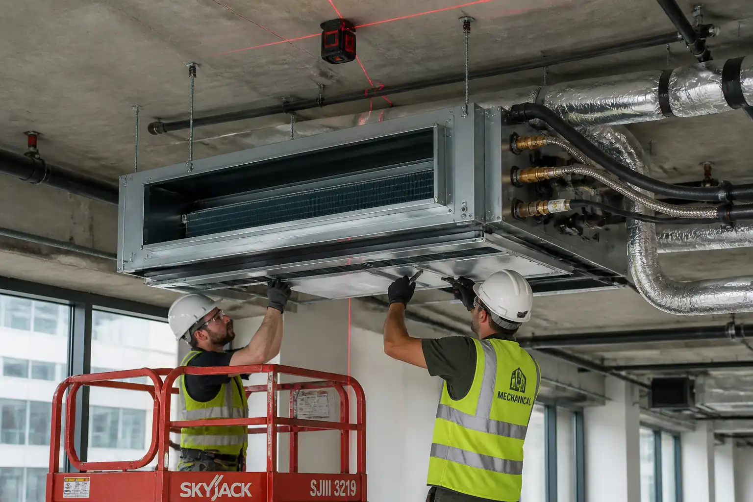
1) Working at Height (ladders/MEWP/mobile scaffold)
- Hazard: Falls from height; falling objects.
- Consequence: Serious injury or fatality; third-party harm.
- Engineering/Procedural Control: Use inspected and tagged ladders (industrial grade) for ≤2.5 m tasks; MEWP/mobile scaffold for higher/long-duration tasks. Maintain 3:1 ladder angle and three points of contact; secure exclusion zone; tool lanyards. MEWP pre-use check and harness/anchor point as required by manufacturer.
- PPE: Hard hat with chin strap, fall arrest harness (for MEWP if required), safety boots, gloves, safety glasses.
- Collective Measure: Barricades and signage; toe-boards on scaffold; spotter for MEWP.
- Inspection/Permit/Supervision: PTW for working at height; daily MEWP inspection; competent operator certification; supervisory sign-off. [Verify per project HSE plan and local regulations]
2) Ceiling/Above-Ceiling Access
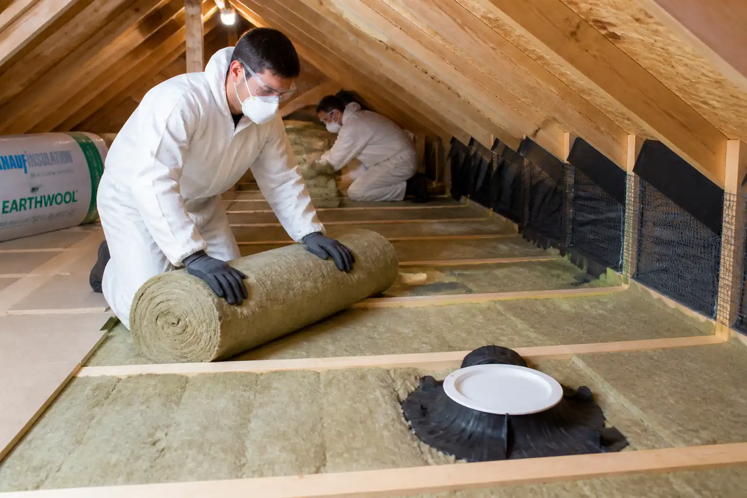
- Hazard: Stepping on fragile ceiling tiles; dust exposure; hidden hazards.
- Consequence: Falls through ceiling; respiratory irritation; eye injuries.
- Engineering/Procedural Control: Use ceiling access panels; support body weight on structure only; use crawling boards if required; vacuum with HEPA when opening spaces; pre-inspect for asbestos/contaminants where applicable.
- PPE: Safety glasses, dust mask (P2/P3 as needed), gloves.
- Collective Measure: Area isolation; spotter.
- Inspection/Permit/Supervision: Ceiling access permit; check as-built services drawings.
3) Drilling/Fixings into Slab/Structure
- Hazard: Striking concealed services; flying debris; vibration.
- Consequence: Electric shock; flooding; service outage; eye injury.
- Engineering/Procedural Control: Scan with approved cable/pipe locator or GPR as required; use drill stoppers; dust extraction; SDS-plus with depth gauge; avoid prohibited zones.
- PPE: Safety glasses/face shield, hearing protection, gloves.
- Collective Measure: Barriers; debris containment; vacuum extraction.
- Inspection/Permit/Supervision: Hot work or drilling permit where required; documented service scan.
4) Electrical/PoE Exposure
- Hazard: Contact with PoE conductors (≤57 Vdc) and energized equipment; ESD damage to electronics.
- Consequence: Minor shock, burns, equipment damage.
- Engineering/Procedural Control: De-energize ports when terminating; use PoE analyzers; follow ESD protocols (wrist strap, mats); no live termination.
- PPE: Insulated gloves (light-duty), safety glasses.
- Collective Measure: Lock-out/tag-out for switch ports where feasible.
- Inspection/Permit/Supervision: Electrical work permit as applicable; supervisor authorization.
5) Manual Handling of MEWP/Equipment
- Hazard: Strains, crush injuries.
- Consequence: Musculoskeletal injuries.
- Engineering/Procedural Control: Team lifts; use trolleys; follow manufacturer lifting points for MEWP batteries/components.
- PPE: Gloves, safety boots.
- Collective Measure: Clear routes; ramps.
- Inspection/Permit/Supervision: Manual handling training; supervisor oversight.
6) Chemical Exposure (Firestop Sealants/Cleaners)
- Hazard: Skin/eye irritation; VOC inhalation.
- Consequence: Dermatitis, respiratory issues.
- Engineering/Procedural Control: Review SDS; ensure ventilation; apply per manufacturer instructions; avoid mixing incompatible products.
- PPE: Nitrile gloves, goggles, masks as per SDS.
- Collective Measure: Local exhaust/ventilation where feasible.
- Inspection/Permit/Supervision: COSHH/chemical permit where required; SDS on site.
7) Noise and Vibration from Drilling
- Hazard: Hearing damage; hand-arm vibration syndrome.
- Consequence: Long-term injury.
- Engineering/Procedural Control: Low-vibration tools; time limits; maintenance of bits.
- PPE: Hearing protection, anti-vibration gloves as needed.
- Collective Measure: Noise barriers if needed.
- Inspection/Permit/Supervision: Exposure monitoring where mandated.
8) Housekeeping and Trip Hazards
- Hazard: Patch leads, tools, packaging in walkways.
- Consequence: Slips, trips, falls.
- Engineering/Procedural Control: Cable mats/ramps; tidy as you go; daily clean-down.
- PPE: Safety boots.
- Collective Measure: Barricade cables crossing corridors.
- Inspection/Permit/Supervision: Supervisor inspections; housekeeping checklist.
Environmental Controls
Controls and Good Practice
- Dust Control: Use vacuum attachments on drills; damp-wipe surfaces after above-ceiling works. Avoid releasing dust into HVAC returns; isolate AHUs if necessary.
- Noise Management: Schedule drilling during permitted hours; use low-noise tools; notify occupants.
- Waste Management: Segregate packaging (cardboard/plastic), cable offcuts, and electronic waste. Dispose of failed electronics under WEEE or local e-waste rules. Maintain waste transfer notes.
- Chemical Handling: Store firestop sealants in bunded trays; prevent spills; follow SDS for disposal.
- Energy and Idle Reduction: Power down tools when not in use; minimize MEWP idle time.
- Protection of Finishes: Use drop cloths for ceiling works; avoid staining tiles; replace damaged tiles immediately.
- Environmental Incidents: Report spills; have spill kits available; stop work if dust/noise exceed project limits. [Verify per project HSE plan and local regulations]
Quality Assurance / Quality Control
QA/QC Controls
- Submittals: Approve AP models, brackets, cabling, labels, firestop systems before installation.
- Calibration: Ensure certifiers, analyzers, torque tools have valid calibration certificates.
- Workmanship: Enforce bend radius, pulling tension, and termination standards; no cable kinks or sheath damage.
- Labeling: Implement TIA-606-C scheme consistently (TR-panel-port to AP ID linkage). Affix durable labels to APs, outlets, patch panels.
- Testing: 100% cable certification (Cat6/Cat6A). 100% PoE verification for live APs. RF survey with heatmaps for representative areas or 100% as specified.
- Documentation: Maintain IRs, MIRs, test reports (PDF + native files), controller snapshots, as-builts (DWG/BIM), asset register, warranties.
- Nonconformities: Log NCRs; implement corrective actions and retesting.
- Handover: Compile MDR/O&M including datasheets, spares list, user guides, training records.
Attachments
- Sample checklists: Material Receipt, Setting-Out, AP Mounting, Labeling.
- ITP forms and inspection request (IR) templates.
- Test plan template covering cable certification, PoE checks, RF survey, functional/security tests.
- Example labeling scheme compliant with TIA-606-C.
- Vendor installation guides and torque specifications.
- SDS for firestop materials and cleaners.
- As-built drawing markers (DWG) and sample asset register (CSV).
This content is a read-only public reference. Download or customize to get an editable version.
ITP preview
The first inspection activities from the linked ITP for Method Statement – Wireless Access Point (WAP) Installation and Commissioning:
| Activity | Inspection / Test | Acceptance Criteria | Responsibility | Record |
|---|---|---|---|---|
| Material receipt and storage | Check model, quantity, condition, certificates | Approved submittals; materials undamaged; environmental conditions within vendor limits | QA/QC, LV Supervisor | MIR, photos |
| Pre-install coordination and setting out | Location, clearances, clashes | Within ±100 mm; no conflicts; agreed ceiling fixing method | LV Supervisor, Architect/MEP, QA/QC | Setting-out checklist, redlines |
| Pathways and firestopping | Tray/conduit routes, supports, UL/EN firestop system details | Supports per TIA-569-D; firestops installed to certified detail and tagged | LV Supervisor, QA/QC | IR, photos, firestop register |
Showing 3 of 11 inspection activities. View full ITP →
Related Inspection and Test Plan
An Inspection and Test Plan (ITP) is available for Method Statement – Wireless Access Point (WAP) Installation and Commissioning. The ITP defines the inspection activities, acceptance criteria, hold and witness points, responsible parties, and records required to verify the work described in this method statement.
View the Method Statement – Wireless Access Point (WAP) Installation and Commissioning ITP →Frequently asked questions
Continue with related Quollnet resources connected to this method statement.