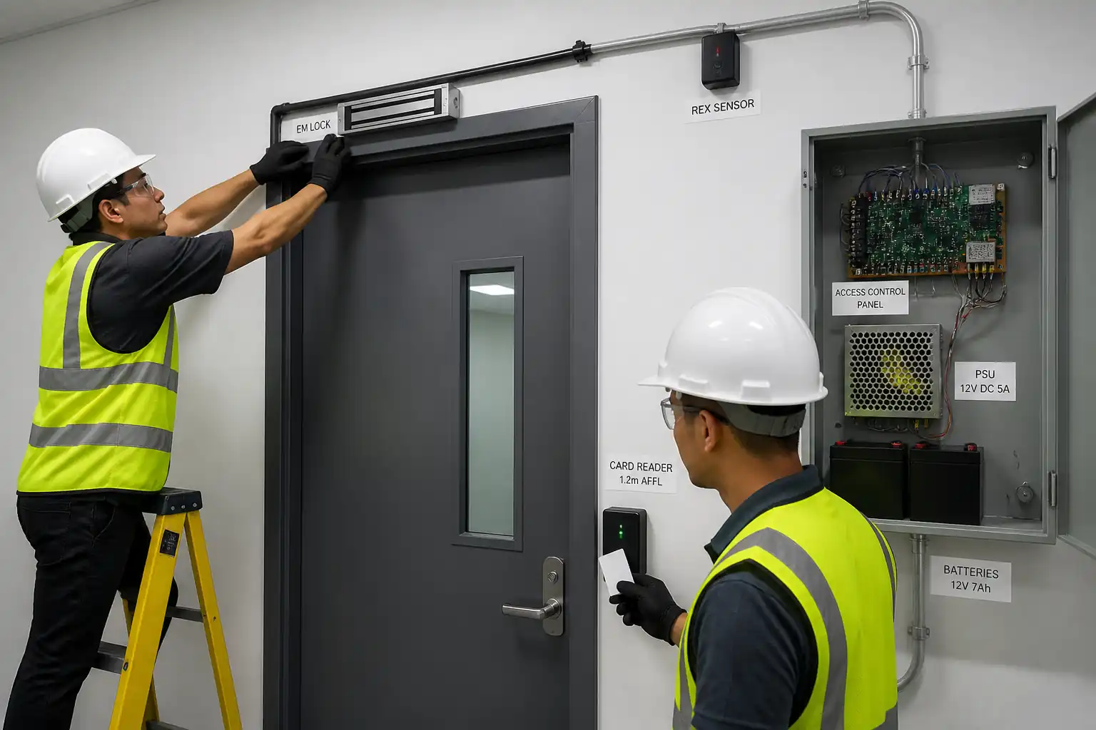

Method Statement: Access Control System Installation, Integration, Testing and Commissioning – Method Statement
AI-assisted method statement with matching ITP, PDF download, and Excel export.
More than a static template
Unlike a downloadable Word or PDF template, this method statement is an AI-assisted editable starting point connected directly to a matching Inspection and Test Plan. Every section is structured, project-adaptable, and ready to export.
- AI-assisted drafting — Customize every section with AI for your specific project scope.
- Linked ITP — A matching inspection and test plan is generated alongside the method statement.
- Multiple export formats — Download as a formatted PDF or editable Excel spreadsheet.
- Editable starting point, not a final document — Review, verify, and adjust all content against your project requirements before use.
Static template vs. Quollnet workflow
| Feature | Static template | Quollnet |
|---|---|---|
| Project-specific content | Manual fill-in required | AI-assisted customization |
| Linked ITP | Separate document, no link | Matching ITP included |
| Export formats | Usually PDF only | PDF and Excel |
| Structured sections | Free-form layout | 13 standardized sections |
| Saved to your account | Local file only | Cloud-saved, reusable |
| Content accuracy | You verify everything | AI-assisted, you still verify |
| Cost | Often free but time-intensive | Free to customize and download |
What you can customize
When you save this method statement to your account, every section becomes editable. The following 13 sections are included:
- Scope — Defines the activity and its boundaries.
- References — Standards, specifications, and drawings.
- Responsibilities — Roles and accountabilities.
- Resources — Labour, plant, and equipment summary.
- Materials — Materials and compliance requirements.
- Equipment — Tools and equipment details.
- Prerequisites — Hold points and pre-conditions.
- Method sequence — Step-by-step construction sequence.
- Safety controls — HSE risk controls and PPE.
- Environmental controls — Environmental mitigation measures.
- QA/QC — Quality inspection and test requirements.
- ITP — Inspection and Test Plan table (has its own page).
- Attachments — Referenced drawings and documentation.
Why this method statement is used
This method statement is used to define and communicate the approved procedure for carrying out method statement: access control system installation, integration, testing and commissioning on site. It ensures the work is planned in advance, the correct resources and controls are in place, and all personnel understand responsibilities, sequence, quality requirements, and safety controls before work begins. It aligns site execution with the documented scope and acceptance expectations.
Who uses this method statement
This method statement is used by contractors, site supervisors, project engineers, QA/QC engineers, HSE officers, consultants, and client representatives. It serves as a shared reference for planning, execution, supervision, inspection, and approval of the activity on site.
When it is prepared and submitted
The method statement is prepared before the work activity starts and submitted as part of the pre-construction documentation package for review and approval.
Who reviews or approves it
The method statement is usually submitted to the client representative, consultant, resident engineer, or project management consultant for review and approval before the work commences.
Important approval note
This method statement is an AI-assisted editable starting point, not a pre-approved document. Before use on any project, all content must be reviewed and approved by the relevant parties (superintendent, principal contractor, or client representative) in accordance with your contract and project quality plan.
For example: if your specification requires a departure from a referenced standard, that departure must be documented and approved separately — this method statement will not capture that automatically. Always verify against your applicable drawings, specifications, and regulatory requirements.
Method statement content
Scope
Overview
This method statement covers the end-to-end delivery of the Access Control System (ACS) for controlled doors, including:
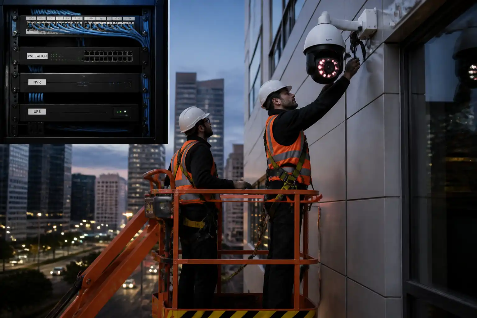
- Supply and installation of: proximity/smart card readers, keypads (if specified), electromagnetic locks, electric strikes, door position switches, request-to-exit (REX) devices (PIR and push-to-exit), emergency break-glass/emergency door release units (EDR), door loops, controllers, input/output modules, power supplies with battery backup, enclosures, patch panels, PoE/network switches (if in scope), and all required cabling and containment.
- Door-by-door coordination with architectural door schedules and hardware sets, fail-safe vs. fail-secure configuration, and fire alarm integration for safe egress.
- Cabling installation in conduits/trunking/cable trays; termination, labeling, and testing to recognized standards.
- System programming: IP addressing, controller enrollment, time schedules, access levels, initial credential enrollment, anti-passback (if applicable), and event/alarm routing.
- Commissioning and functional testing for 100% of controlled doors including egress performance, fire alarm release, power-loss behavior, event logging, and battery autonomy.
- QA/QC inspections, documentation, handover of as-built drawings, test results, O&M manuals, training, and spares.
Exclusions (unless otherwise noted)
- Structural modifications to door frames/leafs beyond drilling/tapping for devices.
- Supply/commissioning of fire detection system (provided by others); interface wiring and cause-and-effect testing are included.
- Door closers, hinges, and mechanical locksets unless specifically identified in the door hardware schedule.
Key Performance Targets [Verify per project specifications]
- Door egress release on REX motion: within 2 s of approach.
- Manual push-to-exit/EDR: immediate release and maintained unlock for ≥30 s.
- Fire alarm input release: immediate release (target <2 s) for affected doors.
- Valid credential access grant: lock release within ≤1 s; relock on door closure within ≤2 s.
- Voltage at lock terminals: within rated voltage ±10% under load.
- Battery autonomy: typically ≥4 h standby with ≥15 min alarm/door operation.
- Reader mounting height: 1200 mm ±50 mm AFFL; push-to-exit 1000–1200 mm AFFL; EDR 1200–1400 mm AFFL; REX PIR at 2200–2400 mm AFFL. [Verify per code and accessibility requirements]
References
| Document Type | Reference / Number | Revision | Notes |
|---|---|---|---|
| Standard | EN 60839-11-1 (and -11-2 as applicable) | [Jurisdiction-dependent] Verify applicability per project specifications. | |
| Standard | UL 294 | For North American jurisdictions; locks also see UL 1034. | |
| Code | NFPA 101 | Coordinate with AHJ/Fire Marshal. | |
| Code | IBC / IFC | [Verify per local adoption]. | |
| Code | NFPA 70 (NEC) | OR IEC 60364 / BS 7671 depending on region. | |
| Standard | IEC 60364 / BS 7671 | [Jurisdiction dependent]. | |
| Standard | ISO/IEC 11801 | ||
| Standard | ANSI/TIA-568.2-D | ||
| Standard | ANSI/TIA-569-D | ||
| Standard | ANSI/TIA-606-C | ||
| Standard | IEEE 802.3af/at/bt | PoE/PoE+/UPoE budgets and classification. | |
| Standard | UL 1034 | Applicable for electromagnetic locks/strikes (region dependent). | |
| Standard | EN 13637 | Where adopted by the AHJ. | |
| Standard | IEC/EN 62368-1 | ||
| Standard | ISO 21542 | For mounting heights and reach ranges; also verify local accessibility codes/ADA. |
Responsibilities
| Role | Responsibility | Name / Party |
|---|---|---|
| Project Manager | Project Manager | Contractor |
| Site Engineer | Site Engineer | Contractor |
| ELV Lead | ELV Lead / Access Control Supervisor | Contractor |
| QA/QC Engineer | QA/QC Engineer | Contractor |
| HSE Officer | HSE Officer | Contractor |
| Technicians | Electricians/ELV Technicians | Contractor |
| Network Engineer | IT/Network Engineer | Contractor/Client IT |
| Door Hardware Specialist | Door Hardware Specialist | Contractor/Subcontractor |
| Commissioning Engineer | Commissioning Engineer | Contractor |
| Client Rep | Client Security Manager / Representative | Client |
Resources
| Resource Type | Description | Quantity | Remarks |
|---|---|---|---|
| Labor | ELV Technicians | As scheduled | |
| Labor | Electrician (mains/PSU) | 1–2 | |
| Labor | Commissioning Engineer | 1 | |
| Labor | HSE Officer | 1 (shared) | |
| Labor | Network Engineer (as needed) | 1 |
Materials
| Material | Specification / Grade | Quantity | Remarks |
|---|---|---|---|
| Readers | UL 294/EN 60839 compliant; Wiegand/OSDP (RS-485) interface. | ||
| Maglocks | UL 1034/UL 294; fail-safe; monitored (bond/door). | ||
| Strikes | UL 1034/UL 294; fire-rated where door is rated. | ||
| DPS | SPDT/DPDT as required; tamper monitored if specified. | ||
| REX PIR / PTE | Adjustable timer and detection range. | ||
| EDR Units | Compliant with local egress standards; normally closed contact opens to release. | ||
| Controllers | UL 294 / EN 60839; TCP/IP with TLS support [Verify]. | ||
| PSU | Rated ≥125% of steady-state load; battery charging per manufacturer. | ||
| Batteries | AH ≥ (Total load A × required h) / 0.8 [Verify]. | ||
| Cables | ISO/IEC 11801; TIA-568.2-D; IEC/UL listings as applicable. | ||
| Containment & Firestopping | NEC/BS 7671; tested firestop systems (UL-EU/ETA). | ||
| Network Components | IEEE 802.3af/at/bt; TIA-568 terminations. | ||
| Labeling & Accessories | As approved in submittals. |
Equipment
| Equipment | Capacity / Type | Quantity | Inspection Required |
|---|---|---|---|
| Drills & accessories | As required | ||
| Ladders/MEWP | As required | ||
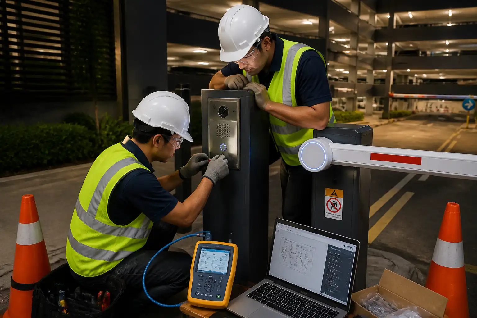
| Fluke DSX or equivalent; PoE test set | 1 set | ||
| Termination tools | 1 set | ||
| Cleaning equipment | As required | ||
| Label printer | 1 |
Prerequisites
- Approved shop drawings: door-by-door wiring diagrams, device schedules, containment layouts, risers, IP addressing plan, labeling schema (TIA-606-C).
- Approved door hardware schedule and fail-safe/fail-secure matrix signed off by Architect, Security, and AHJ/Fire Marshal [Verify per project HSE plan and local regulations].
- Confirm fire alarm interface logic (cause-and-effect) and required door groups; identified release relays/circuits.
- Permits to Work: ceiling access, electrical isolation, work-at-height, drilling/penetrations, confined spaces where relevant.
- Utility/Services check: scan/locate concealed services in drilling zones; asbestos survey clearance where applicable.
- Power availability: dedicated 230/120 VAC circuits for PSUs and/or PoE switches; UPS provision if specified.
- Network readiness: switch ports, VLAN, PoE budget, NTP, IP reservations, firewall rules.
- Materials inspection: verify certifications (UL/EN), model numbers, ratings, and quantities.
- Calibrated tools/testers with certificates.
- Room readiness: controller/PSU backboards installed, environmental conditions within manufacturer limits (typically 0–35°C, RH <85% non-condensing) [Verify per product datasheets].
- Stakeholder access windows and security procedures for credential enrollment.
- Method-specific risk assessment and task briefing/toolbox talk completed.
- Mock-up/first-of-kind door installation approved prior to production rollout.
Method Sequence
| Step | Activity | Description | Responsibility | Inspection / Hold Point |
|---|---|---|---|---|
| 1 | Kick-off & Door Coordination | Hold coordination meeting; verify door list, swing, rating, hardware, fail-safe/fail-secure selection, egress paths, interlocks; update door matrix and drawings. | ELV Lead / Site Engineer | Review/approval of door matrix |
| 2 | Site Survey & Set-out | Survey routes and device locations. Mark reader, EDR, REX heights; mark drilling points using manufacturer templates; verify structural suitability and fire door status. | Site Engineer | Set-out check |
| 3 | Install Containment | Install conduits/trunking/cable tray with supports at 1.2–1.5 m spacing (typ.); maintain 50 mm min separation from LV power or provide barriers; firestop all rated penetrations with tested systems. | Technicians | Fixing and firestop inspection |
| 4 | Cable Pulling & Dressing | Pull CAT6 and control cables; observe bend radius (≥4×OD U/UTP; ≥8×OD F/UTP); max pull tension ~110 N for CAT6 [Verify]; dress and bundle (Velcro preferred), label both ends. | Technicians | In-process cable routing check |
| 5 | Termination - Field Devices | Terminate readers (OSDP/Wiegand), DPS, REX, EDR as per wiring diagrams. Shield/Drain wire grounded at controller end only (typ.) to avoid loops. | Technicians | Termination workmanship check |
| 6 | Termination - Controllers & Panels | Mount controllers and I/O in enclosures; terminate per schematics; torque terminals to manufacturer spec; install fuses/PTS labels; earth bond doors/enclosures as required. | Technicians | Panel build inspection |
| 7 | Lock Installation & Alignment | Install maglocks/strikes using jigs; align armature/keeper; set air gap uniform ≤1 mm; verify door closes freely with closer; install door loops as needed. | Technicians / Door Hardware Specialist | Mechanical alignment check |
| 8 | Power Supplies & Batteries | Mount PSU enclosures; connect 230/120 VAC via isolator; wire 12/24 VDC outputs; install and date batteries; calculate load and autonomy; connect earth. | Electrician / Technician | Electrical inspection |
| 9 | Network/Server Configuration | Configure switches (VLAN, QoS), PoE allocation; set controller IPs, NTP, time zones; apply latest stable firmware; create system backups. | Network Engineer / Commissioning Engineer | Config review |
| 10 | Pre-Power Checks | Verify polarity, continuity, correct fuses, correct addressing; isolate locks for staged energization. | Commissioning Engineer | Pre-energization check |
| 11 | Power-Up & Electrical Testing | Energize PSUs and controllers; monitor inrush; verify lock current draw and voltage drop at farthest door; set PoE priorities. | Commissioning Engineer | Live measurements |
| 12 | Programming & Credential Enrollment | Create access levels, schedules; enroll initial credentials; set door timers (unlock, relock, REX durations); enable anti-passback if required. | Commissioning Engineer / Client Security | Logic review |
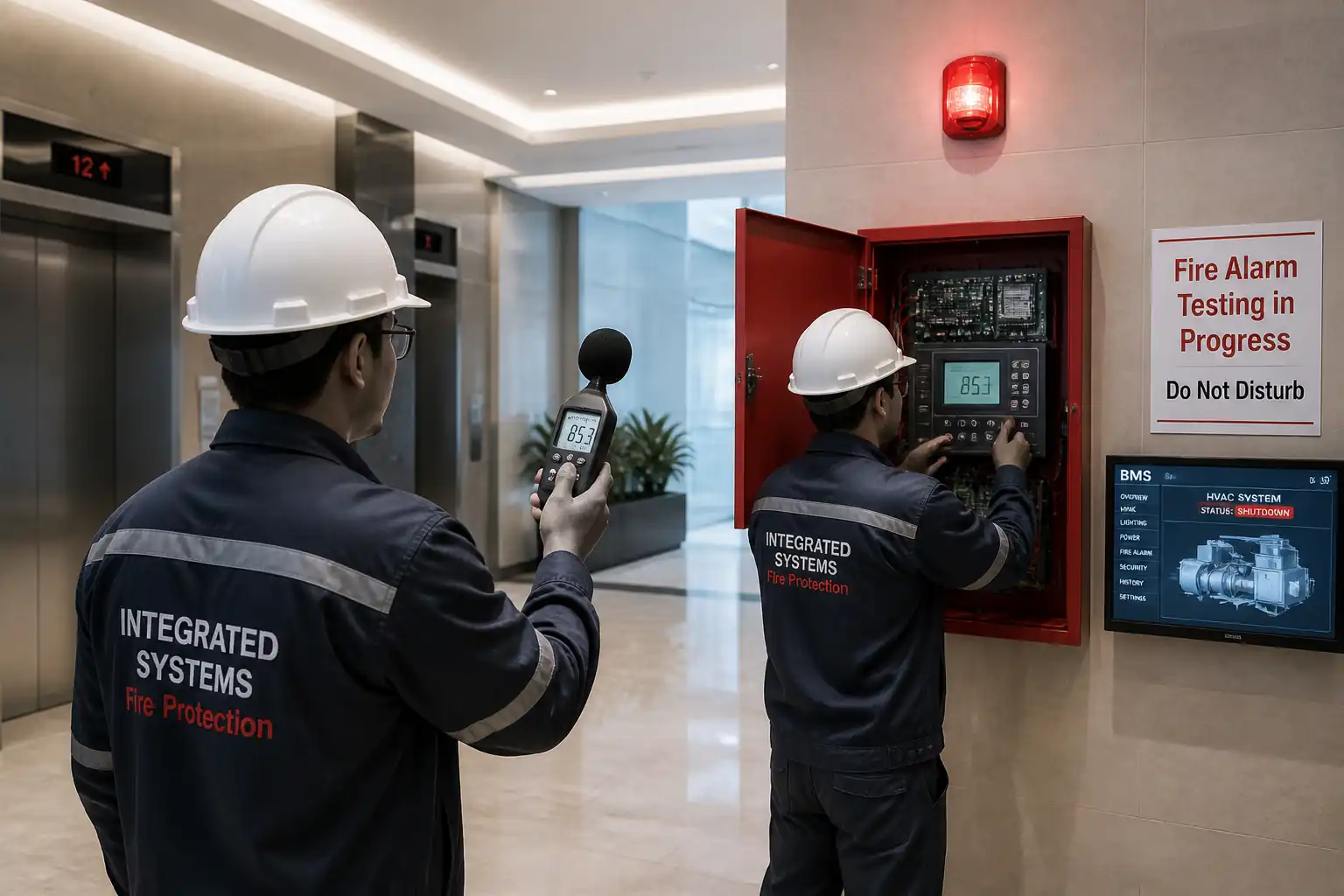
| 13 | Functional Testing (Door-by-Door) | Test each door: authorized/unauthorized attempts; DPS; door-held/forced alarms; REX motion and push-to-exit; EDR; fire alarm release; power fail behavior; key override; event logging. | QA/QC + Commissioning + Client Witness | Witness test |
| 14 | Soak Test & Snag Rectification | Run 24–72 h monitoring; review logs for nuisance alarms; fine-tune REX sensitivity and timers; rectify snags. | Commissioning Engineer | Soak test review |
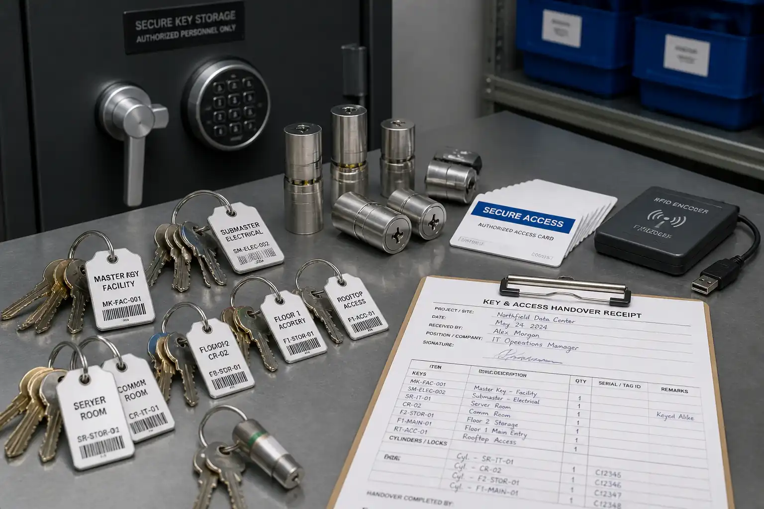
| 15 | Documentation, Training & Handover | Submit as-builts, labeling schedules, cable test certificates, O&M manuals, warranty, spare parts; deliver operator training; transfer admin credentials securely. | Project Manager / ELV Lead | Final QA review |
Safety Controls
Task-specific HSE Controls
1) Hazard: Contact with live electrical circuits (230/120 VAC to PSUs; 24 VDC lock circuits)
- Likely consequence: Electric shock, burns, arc flash (mains), equipment damage.
- Engineering/procedural control: Lock-out/Tag-out (LOTO) for mains circuits; use RCD/RCBO protection; verify dead with approved tester; segregate LV and ELV; install finger-safe terminals and fusing per design; use insulated tools.
- Required PPE: Electrical gloves (for mains work), safety glasses, arc-rated PPE where required [Verify per project HSE plan and local regulations].
- Collective measure: Clearly marked isolation points and barriers; supervised energization.
- Inspection/permit/supervision: Electrical PTW; pre-use inspection of meters; competent electrician to supervise.
2) Hazard: Working at height (ladders/MEWPs for ceiling cabling and REX PIR)
- Likely consequence: Falls causing serious injury.
- Engineering/procedural control: Use podium steps or MEWPs instead of ladders where duration >30 min; secure exclusion zone; maintain three points of contact; inspect ladders/MEWP before use; use full body harness with lanyard in boom lifts.
- Required PPE: Hard hat, safety footwear, fall-arrest system (MEWP), gloves.
- Collective measure: Edge protection/guardrails on platforms; spotter for MEWP movement.
- Inspection/permit/supervision: Work-at-height PTW; operator certification; daily MEWP checklist; supervisor oversight.
3) Hazard: Drilling into concealed services/structures (walls/frames)
- Likely consequence: Electric shock, flooding, gas leak, structural damage.
- Engineering/procedural control: Review as-builts; scan with multi-detector; pilot holes; use depth stops; no hot works; avoid drilling rated steel frames of fire doors without approval.
- Required PPE: Safety glasses/face shield, hearing protection, gloves.
- Collective measure: Temporary barriers and signage; emergency shutoffs identified.
- Inspection/permit/supervision: Penetration PTW; approval from Architect/Fire Door specialist before modifying rated assemblies.
4) Hazard: Door movement and pinch/crush zones during hardware fitting
- Likely consequence: Finger injuries, contusions.
- Engineering/procedural control: Door chocks/holders; communicate before cycling door; use clamps instead of hand-holding armatures.
- Required PPE: Cut-resistant gloves, safety glasses.
- Collective measure: Exclusion zone both sides of door during functional tests.
- Inspection/permit/supervision: Supervisor to brief crew; use test checklist.
5) Hazard: Dust, silica, and debris from drilling/cutting
- Likely consequence: Respiratory irritation; housekeeping hazards.
- Engineering/procedural control: Use tools with dust extraction; wet drilling for masonry if permitted; HEPA vacuum cleanup; avoid creating dust near active IT equipment.
- Required PPE: FFP2/3 respirator as needed, safety glasses, gloves.
- Collective measure: Containment with drop cloths; isolate smoke detectors or fit covers as per Fire Marshal.
- Inspection/permit/supervision: Hot works not applicable; coordinate with facility for detector isolation and re-instatement log.
6) Hazard: Battery handling (SLA/LiFePO4)
- Likely consequence: Chemical exposure, short circuits, lifting strain.
- Engineering/procedural control: Keep terminals covered; correct polarity; use appropriate charger; manual handling aids for heavy units; store in ventilated area.
- Required PPE: Safety glasses, nitrile gloves.
- Collective measure: Spill kit available; insulated mat on bench.
- Inspection/permit/supervision: Check battery date codes; inspect for swelling/leaks; HSE to verify disposal route.
7) Hazard: Data security/PII during credential enrollment
- Likely consequence: Privacy breach, unauthorized access.
- Engineering/procedural control: Use approved enrollment stations; encrypt databases; permissions based on least-privilege; secure admin passwords and backups.
- Required PPE: N/A.
- Collective measure: Controlled access to server room; CCTV coverage of enrollment station (if permitted).
- Inspection/permit/supervision: Client Security oversight; change-control approvals.
8) Hazard: Fire compartment breach at penetrations
- Likely consequence: Loss of fire resistance and smoke spread.
- Engineering/procedural control: Use tested firestop systems; tag each penetration; follow manufacturer installation detail.
- Required PPE: Gloves, safety glasses.
- Collective measure: QA sign-off of each firestop; photographic records.
- Inspection/permit/supervision: Firestop inspection hold point; AHJ spot checks [Verify per local regulations].
9) Hazard: Noise and hand-arm vibration from power tools
- Likely consequence: Hearing loss, HAVS.
- Engineering/procedural control: Select low-vibration tools; limit trigger time; rotate tasks; maintain tools/bits sharp.
- Required PPE: Hearing protection; anti-vibration gloves.
- Collective measure: Work-hour controls; signage for high-noise areas.
- Inspection/permit/supervision: Monitor HAVS exposure; toolbox talk records.
Environmental Controls
- Waste segregation: separate cardboard/plastics, cable offcuts (recyclable copper), electronic waste (controllers, PCBs), and hazardous waste (batteries). Dispose via licensed carriers with manifests.
- Battery management: store on spill tray; avoid deep discharge; recycle per manufacturer and local regulations.
- Firestopping products: use low-VOC where possible; follow curing/ventilation guidance; keep MSDS on site.
- Dust/noise: use HEPA vacuums, dust extraction, and schedule noisy works outside sensitive hours; reinstate smoke detectors promptly after isolation.
- Energy use: optimize PoE budgets; configure sleep/low-power modes where supported; verify PSU efficiency.
- Spill prevention: keep adhesives and lubricants in secondary containment; have spill kits available near work areas.
- Reinstatement: restore finishes (paint, tiles, ceiling tiles) to original condition; remove all temporary labels and debris daily.
- Documentation: maintain environmental inspection checklists and disposal certificates.
QA/QC
Quality Assurance and Control Plan
- Submittals: Obtain approval for equipment data sheets (UL/EN compliance), shop drawings, wiring diagrams, labeling schedules, PSUs/battery calculations, and firestop systems before procurement.
- Material control: Verify deliveries against approved submittals; record serial numbers for controllers and PSUs; store devices in clean, dry conditions.
- Calibration: All test instruments calibrated within past 12 months with certificates.
- Workmanship standards: Follow manufacturer installation instructions; maintain device mounting tolerances and heights; use ferrules and torque-controlled drivers.
- Labeling: Implement TIA-606-C scheme; label both cable ends, panels, terminal blocks, and devices; provide printed schedules in enclosures.
- Cable testing: 100% Cat6 links certified to ISO/IEC 11801 Class E/TIA Cat6; control cables continuity and polarity verified; no IR testing on ELV/data.
- Electrical verification: Measure voltage/current at farthest lock; verify PSU load ≤80% of rating; verify earth bonding.
- Software/config management: Maintain configuration backups; document firmware versions; record admin credentials handover to Client Security.
- Inspection points: Hold Points HP1 (door matrix approval), HP2 (final acceptance). Witness Point WP1 (functional tests/AHJ as required).
- Nonconformance: Record NCRs with corrective actions; retest affected doors.
- Records: As-built drawings, test certificates, checklists, training attendance, warranties, O&M manuals, asset register, and spare parts list.
- Handover criteria: 100% door tests passed; no Category A defects open; documentation complete and accepted by Client.
Attachments
- Approved shop drawings: door schedules, device layout plans, wiring schematics, riser and single-line diagrams.
- Door matrix: fail-safe/fail-secure, fire release groups, access levels summary.
- Manufacturers’ datasheets and certifications (UL 294/EN 60839/UL 1034), PSUs, batteries, locks, controllers, readers.
- Calculations: PSU loading, battery autonomy, voltage drop.
- Test records: Cat6 certification reports, continuity tests, functional test sheets, interface test sheets, power failure tests, soak test report.
- Labeling schedules and panel legends.
- Firestop system submittals and penetration tag register.
- Network configuration export, IP addressing plan, NTP configuration.
- O&M manuals, warranties, spare parts list.
- Training agenda, attendance logs, and competency sign-off.
- Risk Assessment/Method Statement (RA/MS), Permits to Work, toolbox talk records.
This content is a read-only public reference. Download or customize to get an editable version.
ITP preview
The first inspection activities from the linked ITP for Method Statement: Access Control System Installation, Integration, Testing and Commissioning:
| Activity | Inspection / Test | Acceptance Criteria | Responsibility | Record |
|---|---|---|---|---|
| Material receiving inspection | Models/rating per approved submittals; certificates present (UL/EN). | QA/QC Engineer | Material inspection report | |
| Containment installation | Supports at 1.2–1.5 m; separation maintained; firestops installed to tested systems. | Site Engineer / QA/QC | Containment inspection sheet | |
| Cable pulling | Bend radius observed; labeling both ends; no sheath damage. | QA/QC Engineer | Cable pull checklist |
Showing 3 of 15 inspection activities. View full ITP →
Related Inspection and Test Plan
An Inspection and Test Plan (ITP) is available for Method Statement: Access Control System Installation, Integration, Testing and Commissioning. The ITP defines the inspection activities, acceptance criteria, hold and witness points, responsible parties, and records required to verify the work described in this method statement.
View the Method Statement: Access Control System Installation, Integration, Testing and Commissioning ITP →Frequently asked questions
Continue with related Quollnet resources connected to this method statement.