
Method Statement: Installation and Commissioning of Parking Guidance Intercom Points at Entry/Exit Lanes and Payment Machines – Method Statement
AI-assisted method statement with matching ITP, PDF download, and Excel export.
More than a static template
Unlike a downloadable Word or PDF template, this method statement is an AI-assisted editable starting point connected directly to a matching Inspection and Test Plan. Every section is structured, project-adaptable, and ready to export.
- AI-assisted drafting — Customize every section with AI for your specific project scope.
- Linked ITP — A matching inspection and test plan is generated alongside the method statement.
- Multiple export formats — Download as a formatted PDF or editable Excel spreadsheet.
- Editable starting point, not a final document — Review, verify, and adjust all content against your project requirements before use.
Static template vs. Quollnet workflow
| Feature | Static template | Quollnet |
|---|---|---|
| Project-specific content | Manual fill-in required | AI-assisted customization |
| Linked ITP | Separate document, no link | Matching ITP included |
| Export formats | Usually PDF only | PDF and Excel |
| Structured sections | Free-form layout | 13 standardized sections |
| Saved to your account | Local file only | Cloud-saved, reusable |
| Content accuracy | You verify everything | AI-assisted, you still verify |
| Cost | Often free but time-intensive | Free to customize and download |
What you can customize
When you save this method statement to your account, every section becomes editable. The following 13 sections are included:
- Scope — Defines the activity and its boundaries.
- References — Standards, specifications, and drawings.
- Responsibilities — Roles and accountabilities.
- Resources — Labour, plant, and equipment summary.
- Materials — Materials and compliance requirements.
- Equipment — Tools and equipment details.
- Prerequisites — Hold points and pre-conditions.
- Method sequence — Step-by-step construction sequence.
- Safety controls — HSE risk controls and PPE.
- Environmental controls — Environmental mitigation measures.
- QA/QC — Quality inspection and test requirements.
- ITP — Inspection and Test Plan table (has its own page).
- Attachments — Referenced drawings and documentation.
Why this method statement is used
This method statement is used to define and communicate the approved procedure for carrying out method statement: installation and commissioning of parking guidance intercom points at entry/exit lanes and payment machines on site. It ensures the work is planned in advance, the correct resources and controls are in place, and all personnel understand responsibilities, sequence, quality requirements, and safety controls before work begins. It aligns site execution with the documented scope and acceptance expectations.
Who uses this method statement
This method statement is used by contractors, site supervisors, project engineers, QA/QC engineers, HSE officers, consultants, and client representatives. It serves as a shared reference for planning, execution, supervision, inspection, and approval of the activity on site.
When it is prepared and submitted
The method statement is prepared before the work activity starts and submitted as part of the pre-construction documentation package for review and approval.
Who reviews or approves it
The method statement is usually submitted to the client representative, consultant, resident engineer, or project management consultant for review and approval before the work commences.
Important approval note
This method statement is an AI-assisted editable starting point, not a pre-approved document. Before use on any project, all content must be reviewed and approved by the relevant parties (superintendent, principal contractor, or client representative) in accordance with your contract and project quality plan.
For example: if your specification requires a departure from a referenced standard, that departure must be documented and approved separately — this method statement will not capture that automatically. Always verify against your applicable drawings, specifications, and regulatory requirements.
Method statement content
Scope
Overview
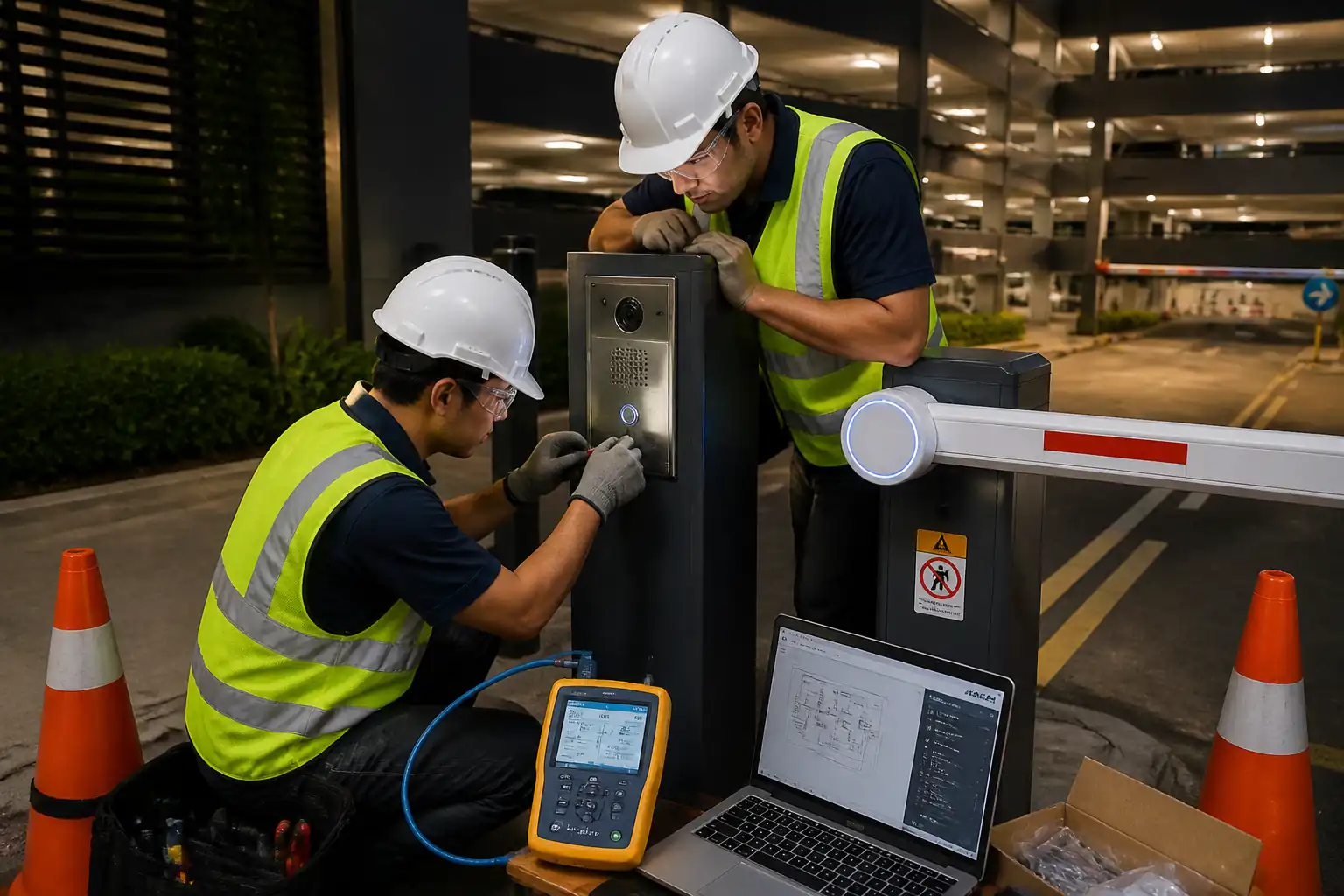
This method statement defines the end-to-end process for installing and commissioning parking guidance intercom points at entry/exit lanes and on/adjacent to automated payment machines. The scope includes civil/architectural adjustments for flush-mount faceplates, ELV cabling, device installation, network and PMS integration, background noise measurement, intelligibility verification (STIPA), and end-to-end voice link testing to the Control Room.
Inclusions
- Supply and installation of flush-mount stainless-steel intercom faceplates with noise-cancelling microphones, loudspeakers, call buttons, and status indicators per approved shop drawings.
- Back boxes, conduit, and penetrations for cabling; fixing and sealing in concrete/masonry/metal pedestals as required.
- Cabling (Cat6 or per manufacturer), termination, labeling, and PoE/power arrangements.
- Network configuration, addressing, VLAN assignment, QoS, and PMS integration.
- Background noise measurement at each intercom location and configuration of DSP/AGC/ANR settings.
- Functional tests, audio intelligibility measurements (STIPA), voice link verification to Control Room, and documentation.
Exclusions
- Civil construction of new pedestals or barrier structures beyond recessing, drilling, and minor making good.
- Fire alarm, CCTV, or PA/VA works not directly part of the intercom system.
- Permanent power network works beyond designated PoE switches or 24 VDC supplies handover points [Verify per project scope].
Locations
- Parking entry lanes at barrier machines.
- Parking exit lanes at barrier machines.
- Automated payment machines (lobbies and open-air).
References
| Document Type | Reference / Number | Revision | Notes |
|---|---|---|---|
| Standard | IEC 60529 | Target: IP54 minimum outdoors [Verify per project specifications]. | |
| Standard | IEC 61672-1 | ||
| Standard | IEC 60268-16 | Benchmark: STIPA ≥ 0.5 for acceptable intelligibility [Verify per project specifications]. | |
| Standard | TIA-568-C.2; ISO/IEC 11801 | All links to PASS Cat6 limits; length ≤ 90 m permanent link. | |
| Standard | IEEE 802.3af/at | Ensure switch PoE budget suffices with 25% margin [Verify per project specs]. | |
| Standard | IEC 60364; NFPA 70; BS 7671 | Apply local code precedence [Verify per local regulations]. | |
| Standard | ASTM A240; ISO 3506 | Use 316 for coastal/outdoor [Verify per project specs]. | |
| Standard | IEC 61000 | ||
| Standard | UL 1479; ASTM E814 | Fire rating to match barrier [Verify per project fire strategy]. | |
| Standard | TIA-606-C; ISO/IEC 14763-2 | ||
| Standard | ISO 21542; ADA 2010 | Target button center 1000 ± 50 mm AFFL [Verify per local code]. |
Responsibilities
| Role | Responsibility | Name / Party |
|---|---|---|
| Project Manager | PM | Contractor |
| Engineer | ELV Lead | Contractor |
| Supervisor | Supervisor | Contractor |
| QA/QC | QA/QC | Contractor |
| HSE | HSE | Contractor |
| IT | IT | Contractor/Client |
| Consultant | Client/Consultant | Client/Consultant |
Resources
| Resource Type | Description | Quantity | Remarks |
|---|---|---|---|
| Labor | Cabling, termination, device installation. | 2-3 | |
| Labor | Core drilling/chiseling for flush-mount recess/back box. | 1 | |
| Labor | Lane closures and vehicle/pedestrian interface control. | 1-2 | |
| Labor | Acoustic measurements, device programming, functional testing. | 1 |
Materials
| Material | Specification / Grade | Quantity | Remarks |
|---|---|---|---|
| SS faceplate | ASTM A240 / ISO 3506 fasteners | Per device | |
| Intercom module | Per manufacturer; IEC 61000 EMC | Per point | |
| Back box | IP54+ | Per point | |
| Cat6 cable | ISO/IEC 11801 | As required | |
| Conduits | IEC 61386 | As required | |
| Fasteners | ISO 3506; ETA | As required | |
| Sealant/Firestop | UL 1479 / ASTM E814 | As required | |
| Labels | TIA-606-C | As required |
Equipment
| Equipment | Capacity / Type | Quantity | Inspection Required |
|---|---|---|---|
| Core drill | Wet/dry | 1 set | |
| Hammer drill | 2 | ||
| Tester | Cat6 | 1 | |
| SLM | Class 1/2 | 1 | |
| STIPA meter | 1 | ||
| PoE tester | 1 | ||
| Laptop | 1 | ||
| Steps/podium | As required | ||
| Vac & wet vac | 1 each |
Prerequisites
- Approved shop drawings, device schedules, method statement, risk assessment, and ITP.
- Material Inspection Requests (MIRs) approved with product datasheets, certificates of conformity, and IP/EMC/accessibility evidence as applicable.
- Confirm network prerequisites: switch ports available, VLAN IDs, QoS policy, IP addressing plan, NTP, SIP/VoIP server details, PMS API credentials/whitelisting [Verify per project specs].
- Confirm power: PoE switch capacity and budget ≥ 125% of calculated load; if external PSU used, provide 24 VDC regulated supply with adequate rating and UPS autonomy [Verify].
- Calibrations: Cable certifier, SLM, STIPA meter calibration certificates valid (<12 months) and checked.
- Accessibility and mounting: finalize heights and reach per code; typical call button centerline 1000 ± 50 mm AFFL [Verify per local regulations].
- Traffic Management Plan (TMP) approved for working in live car parks; lane closure permits arranged [Verify per project HSE plan].
- Utility scan/as-built verification at drill points to avoid services (reinforcement, conduits, power feeds) using cover meter/scan where required.
- PTWs issued: Hot works (if any cutting), Working at Height (if applicable), Electrical works isolation/LOTO, and Excavation (if below ground) [As applicable].
- Coordinate with payment machine/barrier OEM for warranty-safe interface and any embedded cabling or space constraints.
- Pre-delivery inspection of faceplates, back boxes, and devices for finish and completeness.
Method Sequence
| Step | Activity | Description | Responsibility | Inspection / Hold Point |
|---|---|---|---|---|
| 1 | Site handover and setting out | Review approved drawings; mark intercom faceplate extents and height; verify clearance ≥ 1.0 m from barrier arm sweep and vehicle path edges [Verify per OEM and site]. | Site Supervisor | WIR |
| 2 | Isolations and lane control | Implement TMP; cordon area; install signage and barriers; perform LOTO for any power within work zone. | HSE/Supervisor | PTW |
| 3 | Recess/back box preparation | Core drill/chisel recess per back box template; deburr edges; dry-fit back box; ensure recess depth ±3 mm flush tolerance. | ELV/Civil | WIR |
| 4 | Conduits and penetrations | Install conduits and sleeves to nearest cable route; maintain segregation from power (≥50 mm or partition) [Verify per IEC 60364]; seal external entries with IP grommets; apply firestop at rated barriers. | ELV | WIR |
| 5 | Cable pulling and dressing | Pull Cat6 (or specified) through conduit; maintain bend radius ≥4xOD; avoid kinks; leave 300 mm service loop at device and panel ends. | ELV | In-process |
| 6 | Termination and labeling | Terminate to keystone/jack or device per T568B; shield bonding if F/UTP; label both ends per TIA-606-C; torque terminations per vendor. | ELV | WIR |
| 7 | Faceplate and device installation | Fix back box; install gasket; mount intercom module and stainless faceplate with security screws; apply neutral-cure silicone perimeter if outdoors; torque M4 screws to 2.0–2.5 N·m [Verify]. | ELV | WIR |
| 8 | Network/power provisioning | Activate PoE port; assign VLAN/QoS; set static IP/DHCP reservation; configure NTP/SIP; verify PoE class and voltage at jack. | IT/ELV | IT check |
| 9 | PMS integration | Register device with PMS; map to lane/machine ID; verify alarm/events and call routing per matrix. | IT/ELV | Functional |
| 10 | Background noise measurement | Measure LAeq,1min at 1.0 m in front of intercom at busy period using Class 1/2 SLM; record spectrum if available. | Commissioning | Test |
| 11 | Audio tuning and STIPA | Configure DSP/AGC/ANR and mic/speaker gain; conduct STIPA test at user position using approved method. | Commissioning | Test |
| 12 | Voice link verification to Control Room | Initiate call from field; confirm call setup time, duplex operation, volume, clarity; confirm operator can trigger barrier help workflow per matrix. | ELV/Operations | Witness |
| 13 | Finalization and making good | Seal penetrations; clean area; restore lane; remove barriers; update as-builts and O&M manuals. | Supervisor | Final WIR |
Safety Controls
Task-specific HSE Controls
- Hazard: Live traffic in car park lanes
- Likely consequence: Vehicle strike causing serious injury/fatality
- Engineering/procedural control: Approved Traffic Management Plan (cones, barriers, signage, marshal), off-peak scheduling, lane closure, spotter for reversing vehicles
- Required PPE: Hi-vis vest, safety boots, gloves, hard hat
- Collective preventive measure: Physical barriers and delineation; speed bumps/temporary rumble strips if needed
-
Inspection/permit/supervision: TMP approval and PTW; HSE walkdown prior to start; dedicated Traffic Marshal on shift [Verify per project HSE plan]
-
Hazard: Drilling/coring into concrete/masonry
- Likely consequence: Eye injury, silica dust inhalation, embedded service strike
- Engineering/procedural control: Service scan/permit-to-drill; use dust extraction or wet coring with slurry control; guards on tools; set drilling depth stops
- Required PPE: Eye/face protection, hearing protection, FFP2/FFP3 respirator, gloves
- Collective preventive measure: On-tool extraction with HEPA vac; local enclosure/curtain to contain dust
-
Inspection/permit/supervision: Permit-to-drill; tool inspection; supervision by Site Supervisor
-
Hazard: Electrical/PoE/LV exposure during terminations
- Likely consequence: Electric shock, equipment damage
- Engineering/procedural control: LOTO for nearby LV; verify de-energized cables before working; use insulated tools; ESD control for electronics
- Required PPE: Insulated gloves (as required), safety glasses
- Collective preventive measure: Lockable patch panels/switch rooms; barriers to unauthorized access
-
Inspection/permit/supervision: Electrical PTW; competency verification for ELV technicians; periodic audits
-
Hazard: Working at height on steps/podiums
- Likely consequence: Falls causing fractures
- Engineering/procedural control: Use podium steps with guard-rails where possible; inspect ladders; maintain 3-point contact; prohibit overreach
- Required PPE: Non-slip footwear, hard hat
- Collective preventive measure: Podium platforms instead of ladders where space permits
-
Inspection/permit/supervision: Working at Height PTW where applicable; pre-use inspection checklist
-
Hazard: Noise from drilling
- Likely consequence: Hearing loss
- Engineering/procedural control: Select low-noise tools; limit exposure duration; schedule noisy works off-peak
- Required PPE: Class 3–5 hearing protection [Verify]
- Collective preventive measure: Acoustic screens if feasible
-
Inspection/permit/supervision: Noise assessments; HSE monitoring
-
Hazard: Slips from slurry or dust
- Likely consequence: Sprains/fractures
- Engineering/procedural control: Immediate cleanup using wet vac; drip trays for wet coring; slip-resistant mats
- Required PPE: Safety boots with slip-resistant soles
- Collective preventive measure: Housekeeping plan; cordon area until dry
-
Inspection/permit/supervision: Supervisor inspections; HSE housekeeping audits
-
Hazard: Hand tool and sharp edge injuries (faceplate, cut edges)
- Likely consequence: Lacerations
- Engineering/procedural control: Deburr edges; use cut-resistant gloves; correct tool selection
- Required PPE: Cut-resistant gloves, safety glasses
- Collective preventive measure: Pre-install deburring and protective edge trims
-
Inspection/permit/supervision: Tool condition checks; supervisor oversight
-
Hazard: Manual handling of equipment and barriers
- Likely consequence: Musculoskeletal injuries
- Engineering/procedural control: Team lifts; use trolleys; keep loads <25 kg per person [Verify per local guidance]
- Required PPE: Gloves, safety boots
- Collective preventive measure: Mechanical aids for heavy items
-
Inspection/permit/supervision: Manual handling training records; spot checks
-
Hazard: Interface with third-party equipment (payment machines/barriers)
- Likely consequence: Unintended activation, warranty voidance
- Engineering/procedural control: OEM coordination; disconnect power per OEM; method agreed in writing
- Required PPE: As per site standard
- Collective preventive measure: OEM attendance for critical steps if required
- Inspection/permit/supervision: Signed interface permits/records
[Verify per project HSE plan and local regulations]
Environmental Controls
- Dust and slurry management: Use on-tool extraction; if wet coring, collect slurry with wet vac; do not discharge to drains; dispose as per waste plan.
- Noise: Schedule high-noise works off-peak; maintain equipment; use acoustic screens near sensitive receptors.
- Waste segregation: Separate stainless offcuts, cables, packaging; recycle where facilities exist; dispose of sealant/adhesive waste as hazardous if classified.
- Spill prevention: Store sealants/chemicals in trays; have spill kits on hand.
- Energy efficiency: Optimize PoE switch settings and device sleep modes where supported.
- Light pollution (night works): Use task lighting with shielding; avoid glare to drivers.
- Records: Maintain waste transfer notes and environmental checklists.
QA / QC
Quality Controls
- Submittals: Shop drawings, device datasheets, cable schedules, IP/EMC/accessibility evidence, and method/ITP approvals before work.
- Material verification: MIRs with certificates for stainless grade, IP rating, and compliance to TIA/ISO cabling standards.
- Calibration: Valid calibration certificates for SLM, STIPA analyzer, and cable certifier; verify serial numbers in test sheets.
- Work Inspection Requests (WIRs): Hold points at recess/back box, conduit/penetrations, terminations, and pre-cover-up checks.
- Cable testing: 100% Cat6 permanent link certification; retain PDF result files signed by QA/QC.
- Acoustic tests: Record LAeq,1min per location; STIPA results with device settings snapshot.
- Functional tests: Call initiation time, duplex check, latency, PMS event logging, and control room operator acknowledgment records.
- Labeling and documentation: TIA-606-C compliant IDs; as-built drawings with device IDs, cable routes, IP addresses, VLANs.
- Snag management: NCR/Snag list with rectification and re-test evidence.
- Handover dossier: Approved ITP, WIRs, test results, O&M manuals, training attendance, warranties, and spares list.
Attachments
- Typical intercom faceplate and back box detail (flush-mount) – drawing reference.
- Schematic: Intercom endpoint to PoE switch/PMS network topology.
- Device schedule with IP addresses, VLANs, and location references.
- Test sheets: Cable certification, background noise log, STIPA report, functional call checklist.
- Risk assessment and TMP sketches.
- O&M templates and manufacturer datasheets.
- Firestop system details and approvals (if applicable).
This content is a read-only public reference. Download or customize to get an editable version.
ITP preview
The first inspection activities from the linked ITP for Method Statement: Installation and Commissioning of Parking Guidance Intercom Points at Entry/Exit Lanes and Payment Machines:
| Activity | Inspection / Test | Acceptance Criteria | Responsibility | Record |
|---|---|---|---|---|
| Material receipt and verification | Check model, IP rating, stainless grade, certificates | Matches approved submittal; no damage; certificates present | QA/QC | MIR, photos |
| Setting out and mounting height | Measure location and AFFL height | Within ±10 mm horizontally; 1000 ± 50 mm AFFL [Verify] | Site Supervisor/QA | WIR, measurement sheet |
| Back box recess and fixing | Dimensional/plumb check; surface flushness | Flush tolerance 0 to +1 mm; level/plumb ≤2 mm/1 m | QA/QC | WIR, photos |
Showing 3 of 13 inspection activities. View full ITP →
Related Inspection and Test Plan
An Inspection and Test Plan (ITP) is available for Method Statement: Installation and Commissioning of Parking Guidance Intercom Points at Entry/Exit Lanes and Payment Machines. The ITP defines the inspection activities, acceptance criteria, hold and witness points, responsible parties, and records required to verify the work described in this method statement.
View the Method Statement: Installation and Commissioning of Parking Guidance Intercom Points at Entry/Exit Lanes and Payment Machines ITP →Frequently asked questions
Continue with related Quollnet resources connected to this method statement.