
Method Statement – IP Telephone System Installation and Commissioning – Method Statement
AI-assisted method statement with matching ITP, PDF download, and Excel export.
More than a static template
Unlike a downloadable Word or PDF template, this method statement is an AI-assisted editable starting point connected directly to a matching Inspection and Test Plan. Every section is structured, project-adaptable, and ready to export.
- AI-assisted drafting — Customize every section with AI for your specific project scope.
- Linked ITP — A matching inspection and test plan is generated alongside the method statement.
- Multiple export formats — Download as a formatted PDF or editable Excel spreadsheet.
- Editable starting point, not a final document — Review, verify, and adjust all content against your project requirements before use.
Static template vs. Quollnet workflow
| Feature | Static template | Quollnet |
|---|---|---|
| Project-specific content | Manual fill-in required | AI-assisted customization |
| Linked ITP | Separate document, no link | Matching ITP included |
| Export formats | Usually PDF only | PDF and Excel |
| Structured sections | Free-form layout | 13 standardized sections |
| Saved to your account | Local file only | Cloud-saved, reusable |
| Content accuracy | You verify everything | AI-assisted, you still verify |
| Cost | Often free but time-intensive | Free to customize and download |
What you can customize
When you save this method statement to your account, every section becomes editable. The following 13 sections are included:
- Scope — Defines the activity and its boundaries.
- References — Standards, specifications, and drawings.
- Responsibilities — Roles and accountabilities.
- Resources — Labour, plant, and equipment summary.
- Materials — Materials and compliance requirements.
- Equipment — Tools and equipment details.
- Prerequisites — Hold points and pre-conditions.
- Method sequence — Step-by-step construction sequence.
- Safety controls — HSE risk controls and PPE.
- Environmental controls — Environmental mitigation measures.
- QA/QC — Quality inspection and test requirements.
- ITP — Inspection and Test Plan table (has its own page).
- Attachments — Referenced drawings and documentation.
Why this method statement is used
This method statement is used to define and communicate the approved procedure for carrying out method statement – ip telephone system installation and commissioning on site. It ensures the work is planned in advance, the correct resources and controls are in place, and all personnel understand responsibilities, sequence, quality requirements, and safety controls before work begins. It aligns site execution with the documented scope and acceptance expectations.
Who uses this method statement
This method statement is used by contractors, site supervisors, project engineers, QA/QC engineers, HSE officers, consultants, and client representatives. It serves as a shared reference for planning, execution, supervision, inspection, and approval of the activity on site.
When it is prepared and submitted
The method statement is prepared before the work activity starts and submitted as part of the pre-construction documentation package for review and approval.
Who reviews or approves it
The method statement is usually submitted to the client representative, consultant, resident engineer, or project management consultant for review and approval before the work commences.
Important approval note
This method statement is an AI-assisted editable starting point, not a pre-approved document. Before use on any project, all content must be reviewed and approved by the relevant parties (superintendent, principal contractor, or client representative) in accordance with your contract and project quality plan.
For example: if your specification requires a departure from a referenced standard, that departure must be documented and approved separately — this method statement will not capture that automatically. Always verify against your applicable drawings, specifications, and regulatory requirements.
Method statement content
Scope
Overview
This method statement covers the end-to-end installation and commissioning of the IP telephone system, including:
- Voice/data outlet preparation at work areas
- Horizontal cabling pull and terminations (faceplates and patch panels)
- Rack dressing and cable management
- Device labeling per TIA-606 scheme
- Patch leads deployment and switch port coordination (PoE, VLAN, QoS)
- IP handset installation, registration, and functional testing
- Emergency/priority extension verification where applicable
- 100% certification testing of permanent links and required channel tests
- QA/QC inspections, records, as-built documentation, training, and handover
Inclusions
- Work in occupied or live-network environments under approved change windows
- Firestopping of penetrations
- Bonding/earthing of racks and metallic pathways [Verify per project specifications]
Exclusions
- Core backbone network design, PBX/Call Manager software configuration beyond port/VLAN coordination
- Civil works and power distribution (by others)
- Raised floor/ceiling construction (by others)
References
| Document Type | Reference / Number | Revision | Notes |
|---|---|---|---|
| Standard | ISO/IEC 11801-1; ISO/IEC 14763-2; EN 50173/50174 series | Cabling performance and testing requirements. | |
| Standard | ANSI/TIA-568.2-D; ANSI/TIA-569-D; ANSI/TIA-606-C; ANSI/TIA-607-D | Balanced twisted-pair, pathways/spaces, administration/labeling, bonding/earthing. | |
| Standard | IEEE 802.3 (incl. 802.3af/at/bt); IEEE 802.1Q; IEEE 802.1X | PoE power, VLAN tagging, network access control. | |
| Standard | IEC 62368-1 | Safety requirements for ICT equipment. | |
| Code | IEC 60364 series or NFPA 70 (NEC) [Verify per jurisdiction] | LV installations, segregation and earthing references. | |
| Standard/Test Method | UL 1479; ASTM E814; EN 1366-3 | Penetration firestop systems. | |
| Guideline | BICSI TDMM (latest); BICSI 005/006 [Verify applicability] | Design and installation best practice. |
Responsibilities
| Role | Responsibility | Name / Party |
|---|---|---|
| PM | Project Manager | Contractor |
| Lead Engineer | ICT Lead Engineer | Contractor |
| Supervisor | Site Supervisor / Foreman | Contractor |
| QA/QC | QA/QC Engineer | Contractor |
| HSE | HSE Officer | Contractor |
| Network Admin | Client Network Administrator (with Contractor support) | Client |
| Technicians | Structured Cabling Technicians | Contractor |
| T&C Tech | Test & Commissioning Technician | Contractor |
| Firestop | Approved Firestop Installer | Specialist |
| Doc Control | Document Controller with ICT Lead | Contractor |
Resources
| Resource Type | Description | Quantity | Remarks |
|---|---|---|---|
| Manpower | 1 Supervisor, 2–6 Cabling Technicians, 1 QA/QC, 1 HSE, 1 Test Technician, 1 Firestop Installer (as needed). [Verify per project] | 6–10 | Adjust to program and access constraints. |
| Client resource | Client Network Admin available during commissioning/change windows. | As required |
Materials
| Material | Specification / Grade | Quantity | Remarks |
|---|---|---|---|
| Cat6/6A cable | Max pull tension ≤110 N (typ. UTP) [Verify]; min bend radius ≥4x OD (UTP) / ≥8x OD (shielded) [Verify]. | As per BOQ | |
| Keystone jacks & faceplates | TIA/EIA pinout T568A or T568B per project (consistent). | As per drawings | |
| Patch panels | As per rack layouts | ||
| Patch leads | As scheduled | ||
| Label media | As required | ||
| Firestop | As required | ||
| Racks & MGMT | Per layouts | ||
| IP phones | As per BOQ |
Equipment
| Equipment | Capacity / Type | Quantity | Inspection Required |
|---|---|---|---|
| Copper certifier | 1–2 sets | ||
| PoE tester | 1 | ||
| Label printer | 1 | ||
| IDC tools | Sets per crew | ||
| Ladders/drills | As required | ||
| Admin laptop | 1 per engineer |
Prerequisites
Approvals and Readiness
- Approved shop drawings, riser diagrams, outlet schedules, rack elevations.
- Approved materials and vendor data sheets.
- ITP and this Method Statement approved by Client/Consultant.
- Permits to Work (ceilings, hot works if drilling creates sparks, working at height) [Verify per project HSE plan and local regulations].
- Network change request approved with defined maintenance window.
Site Conditions
- TR/ER rooms complete: racks installed, dedicated power and UPS available, environmental control 18–27°C and RH 40–60% [Verify per project specifications].
- Pathways (trays, conduits) installed and inspected; penetrations available.
- Bonding/earthing for racks and metallic pathways prepared per TIA-607-D.
- Housekeeping: areas clear; existing services identified and protected.
Technical Inputs
- Finalized port schedule: outlet IDs, patch panel mapping, switch port/VLAN/QoS plan.
- IP addressing, DHCP scopes, option strings (e.g., LLDP-MED/Option 66/150) and SIP/call manager reachability defined [Verify per project specifications].
- Emergency/priority extension list and location mapping (E911/E112 or site control room) agreed with Client [Verify per local regulations].
Tools & Calibration
- Certification testers within calibration validity; firmware updated.
- Label printer media loaded with approved schema.
- Test laptops have access credentials and approved configurations.
Method Sequence
| Step | Activity | Description | Responsibility | Inspection / Hold Point |
|---|---|---|---|---|
| 1 | Inbound material inspection | Verify delivered cables, jacks, panels, phones, and patch cords against approvals; check batch numbers and physical condition. | QA/QC Engineer | Visual inspection |
| 2 | Pathway and room readiness check | Confirm trays/conduits, penetrations, rack installation, power/UPS, bonding points. | Site Supervisor | Joint walkdown |
| 3 | Cable pulling preparation | Plan routes; install pull strings; label both ends; ensure reels dispensed to avoid kinks; install temporary dust protection at TR. | Supervisor/Technicians | |
| 4 | Horizontal cable pulling | Pull Cat6/6A from TR to WA. Maintain bend radius ≥4x OD (UTP) or ≥8x OD (shielded); max pull tension ≤110 N (typ.) [Verify]. Avoid cable tie over-tightening; use Velcro. | Technicians | In-process |
| 5 | Outlet box and faceplate prep | Install back box/surface box flush and level; set faceplate; fit keystone shutter as applicable. | Technicians | Visual |
| 6 | Work-area termination | Terminate cable at keystone per T568A or T568B (project-selected). Maintain untwist ≤13 mm (0.5 in). Trim jacket minimally; install strain relief. | Technicians | Visual + continuity (optional) |
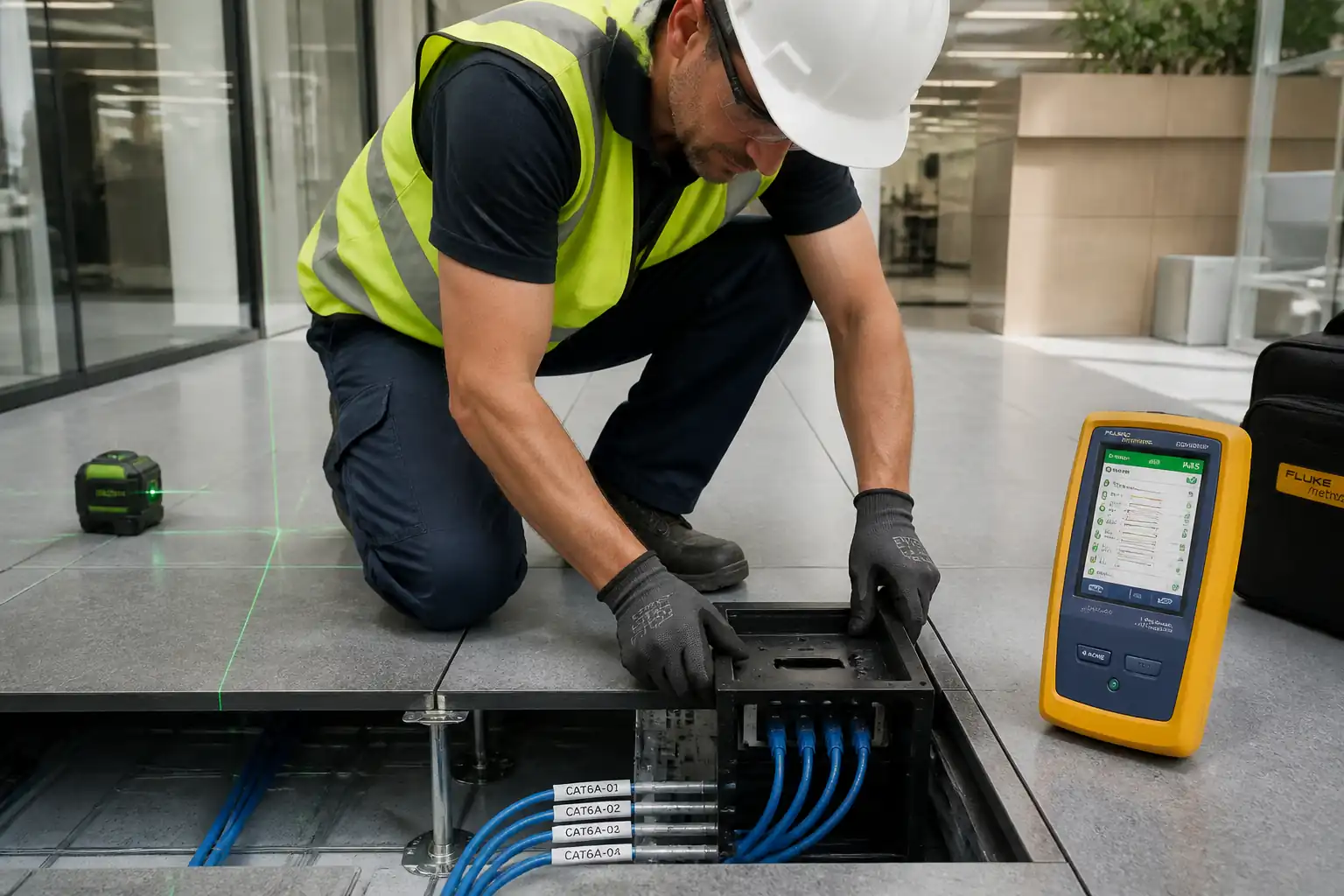
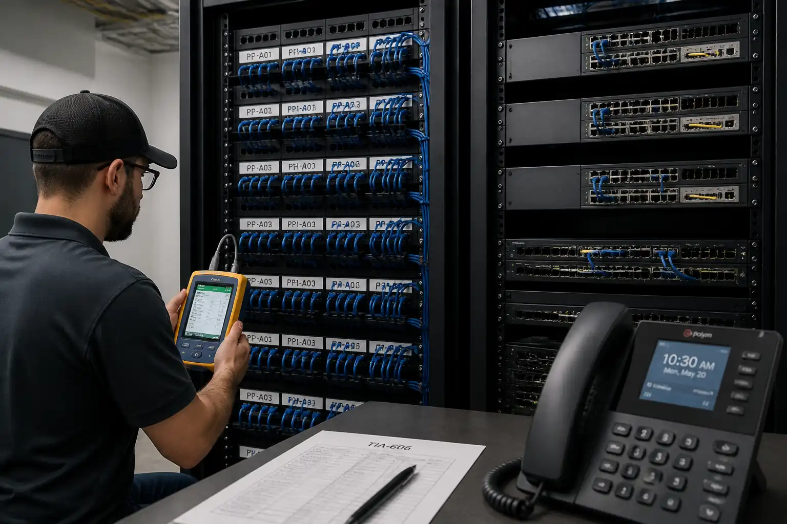
| 7 | Patch panel dressing and termination | Route cables via rear managers; label per TIA-606-C; terminate to panel IDC; provide service loop (typ. 1–2 m in TR) neatly coiled. | Technicians | Visual |
| 8 | Bonding and grounding | Bond racks and metallic pathways to telecom earthing busbar per TIA-607-D. | Technicians | Continuity check |
| 9 | Firestopping of penetrations | Install tested firestop systems to sleeves/penetrations after cable pull; apply identification labels. | Firestop Installer | Consultant witness |
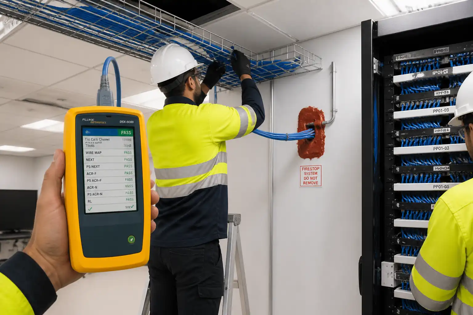
| 10 | Permanent link certification | Test each outlet-to-panel permanent link using Level V accuracy tester to ISO/IEC Class E/EA or TIA Cat6/6A limits as specified. | Test Technician | Witness |
| 11 | Labeling and administration | Apply machine-printed labels to jacks, patch panels, racks, and patch cords per approved scheme (e.g., TR-RackU-Panel-Port / Room-Outlet-Port). Update register. | Technicians/Doc Control | Visual |
| 12 | Switch port preparation | Coordinate with Client IT to configure access ports: voice VLAN, data VLAN (if pass-through), QoS (DSCP EF 46), LLDP/LLDP-MED, PoE class/limits, PortFast, security (802.1X/MAB) per design. | Client Network Admin | Config review |
| 13 | Patching | Deploy patch cords in TR and at WA; avoid tension; use managers. Typical TR patch length ≤5 m; WA ≤3 m [Verify]. | Technicians | Visual |
| 14 | IP handset installation | Assemble stands/handsets; connect to WA outlet; allow boot and provisioning via DHCP/LLDP-MED or static per design. | Technicians | Functional check |
| 15 | Functional call testing | Place inbound/outbound and internal calls; check audio quality (MOS subjective), call features (hold, transfer, voicemail light). | T&C Technician | Witness |
| 16 | Emergency/priority extension verification | Dial emergency/priority number; verify connection and location string/ALI where mandated. | T&C Technician with Client | Witness (Client/HSE) |
| 17 | PoE and power budget check | Measure per-port PoE voltage/current; confirm switch PoE budget vs. connected load with 20% margin [Verify]. | T&C Technician/Network Admin | Measurement |
| 18 | Documentation & handover | Compile as-builts, port maps, labeling registers, certified test results, configs, training records; conduct client demonstration. | ICT Lead/Doc Controller | Final review |
Safety Controls
Task-specific Hazards and Controls
- Hazard: Work at height on steps/towers when accessing ceiling outlets.
- Likely consequence: Fall causing injury.
- Engineering/procedural control: Use inspected podium steps/towers; maintain 3-point contact; no overreaching; spotter for ladder moves; tools tethered.
- Required PPE: Hard hat, safety shoes, gloves, eye protection.
- Collective measure: Barricade drop zone; exclude non-essential personnel.
-
Inspection/permit/supervision: Pre-use ladder inspection; Working at Height permit where required; supervisor sign-off. [Verify per project HSE plan and local regulations]
-
Hazard: Ceiling void dust/fibers or legacy asbestos in refurbishment.
- Likely consequence: Respiratory irritation or asbestos exposure.
- Engineering/procedural control: Review asbestos register; do not disturb suspect materials; use HEPA-vacuum and dust extraction during drilling.
- Required PPE: FFP2/FFP3 respirator, goggles.
- Collective measure: Enclose area with dust sheets; negative air if needed.
-
Inspection/permit/supervision: Permit to access ceiling; asbestos clearance where applicable.
-
Hazard: Interaction with live network equipment and PoE (up to 90 W at ~57 V DC).
- Likely consequence: Minor shock, spark, equipment damage.
- Engineering/procedural control: Disable ports before patching where feasible; cover unused power contacts; follow change management; ESD precautions.
- Required PPE: Anti-static wrist strap when handling electronics; safety glasses.
- Collective measure: Controlled access to TR; no food/drink.
-
Inspection/permit/supervision: Approved change ticket; IT supervision for cutover.
-
Hazard: Power/hand tool use (drilling, punching).
- Likely consequence: Cuts, eye injury, silica dust.
- Engineering/procedural control: Use drill with dust extraction and depth stop; secure work; use correct bits; keep guards in place.
- Required PPE: Safety glasses/face shield, gloves, hearing protection if >85 dBA.
- Collective measure: Set up exclusion zone, signage.
-
Inspection/permit/supervision: Pre-use tool inspection; PAT where applicable.
-
Hazard: Manual handling of reels, racks, and ladders.
- Likely consequence: Strain or crush injuries.
- Engineering/procedural control: Team lifts; use trolleys; keep loads <25 kg per person [Verify].
- Required PPE: Gloves, safety shoes.
- Collective measure: Planned storage and lift routes.
-
Inspection/permit/supervision: Manual handling training; supervisor monitoring.
-
Hazard: Firestopping chemicals (sealants/foams).
- Likely consequence: Skin/eye irritation; inhalation risk.
- Engineering/procedural control: Follow SDS; use in ventilated area; apply per system detail; avoid incompatible materials.
- Required PPE: Nitrile gloves, goggles, long sleeves.
- Collective measure: Spill kit available; waste contained.
-
Inspection/permit/supervision: SDS on site; COSHH assessment [Verify per local regulations].
-
Hazard: Trip hazards from loose patch cords and offcuts.
- Likely consequence: Slips, trips, falls.
- Engineering/procedural control: Maintain housekeeping; use cable managers; remove offcuts promptly.
- Required PPE: Safety shoes.
- Collective measure: Keep walkways clear; cord covers across aisles.
-
Inspection/permit/supervision: Daily HSE inspections.
-
Hazard: UPS battery rooms or energized panels adjacent to racks.
- Likely consequence: Electric shock, arc flash (if energized panels accessed).
- Engineering/procedural control: No access to energized panels by telecom crew; coordinate lockout with electrical team if needed.
- Required PPE: As per electrical PTW if panels accessed by authorized electricians only.
- Collective measure: Barriers and signage.
- Inspection/permit/supervision: Electrical PTW and qualified personnel only.
Environmental Controls
- Waste segregation: Collect copper offcuts and plastic reels separately for recycling; dispose of mixed waste in designated skips. WEEE-compliant disposal for faulty electronics and phones.
- Dust/noise: Use HEPA vacuums and dust extraction; limit noisy activities to permitted hours; provide hearing protection if levels exceed 85 dBA.
- Chemical handling: Store firestop sealants in bunded trays; avoid spills; follow SDS; low-VOC products preferred where available.
- Energy and cooling: Keep TR doors closed; do not obstruct CRAC/AC returns; maintain temperature/humidity within specs during testing.
- Packaging reduction: Request bulk-pack keystones/patch cords where acceptable; remove packaging off-site or to central waste area daily.
- Spill response: Maintain spill kits for sealants/cleaners; report and clean immediately.
- Environmental permits: Follow building environmental plan; any discharge to drainage is prohibited. [Verify per project HSE plan and local regulations]
QA/QC
Hold and Witness Points
- H: Pathway and room readiness (pre-install walkdown)
- W: Terminations (sample check each area), labeling application, permanent link testing (witness), emergency call testing (H)
Inspection and Testing
- 100% permanent link certification to ISO/IEC Class E (Cat6) or EA (Cat6A) or as specified. Test parameters include Wiremap, Length, Insertion Loss, NEXT/PSNEXT, ACR-F/PSACR-F, Return Loss; TCL/ELTCTL if required by spec.
- Channel testing where required after patching, using approved limits. Typical total channel ≤100 m including patch cords [Verify per project specifications].
- Visual inspections: bend radius, strain relief, dressing, labeling consistency, separation from power.
- PoE verification: spot-check per TR at least 10% of phones or minimum 5 devices, whichever greater [Verify], measure class/voltage/current; confirm switch PoE budget with ≥20% headroom [Verify].
- Functional tests: minimum 1 call in/out per phone; for emergency extensions, witnessed test per local protocol.
Acceptance Criteria
- All permanent links: PASS to selected standard with no marginal failures.
- Labeling: matches approved TIA-606-C scheme and as-built database; panel labeling aligns to port map.
- Firestops: installed per listed system with identification labels.
- Documentation: complete and signed ITRs; calibrated test reports (vendor native + PDF), MAC/SN register, port/VLAN map, training attendance.
Nonconformance and Corrective Action
- Record defects on NCR/punch list; rectify (re-terminate/replace) and retest failed links; update records with new results; re-inspect firestops if disturbed.
Records and Handover
- As-built drawings: outlet IDs, cable routes (schematic), patch panel and switch port mapping.
- Certification test result files in original format (XML) and PDFs, organized by TR and panel.
- Firmware/calibration certificates for test sets.
- O&M manuals, warranty letters, and training materials.
Attachments
- Approved shop drawings, riser diagrams, and outlet schedules
- Rack elevations and patch panel layouts
- Labeling scheme and numbering convention (TIA-606 compliant)
- Port/VLAN/QoS configuration plan and approved change tickets
- Material approvals and manufacturers’ data sheets
- Calibration certificates for certification testers and PoE meters
- Material Inspection Reports and Termination ITRs
- Firestop system submittals and installation records with photos
- Certified permanent link/channel test results (native files + PDFs)
- Device register (MAC, serial, extension, location)
- PoE budget calculation and verification logs
- Training materials and attendance sheet
- O&M manuals and warranties
- Handover dossier index and acceptance certificate
This content is a read-only public reference. Download or customize to get an editable version.
ITP preview
The first inspection activities from the linked ITP for Method Statement – IP Telephone System Installation and Commissioning:
| Activity | Inspection / Test | Acceptance Criteria | Responsibility | Record |
|---|---|---|---|---|
| Material receipt inspection | Check against approvals; verify certificates and condition | Compliant with approved submittals; no damage; correct categories (Cat6/6A) | QA/QC Engineer | Material Inspection Report (MIR) |
| Pathway and TR readiness | Walkdown of pathways, separations, racks, power/UPS, bonding points | Per TIA-569-D/EN 50174-2; segregation maintained; TR environment within spec | QA/QC + Consultant | Pre-Installation Checklist (signed) |
| Cable pulling (in-process) | Observe handling, bend radius, pull tension methods | No sheath damage; bend radius ≥4x OD (UTP)/≥8x OD (shielded); no over-tight ties | Supervisor/QA | In-Process Inspection Sheet |
Showing 3 of 12 inspection activities. View full ITP →
Related Inspection and Test Plan
An Inspection and Test Plan (ITP) is available for Method Statement – IP Telephone System Installation and Commissioning. The ITP defines the inspection activities, acceptance criteria, hold and witness points, responsible parties, and records required to verify the work described in this method statement.
View the Method Statement – IP Telephone System Installation and Commissioning ITP →Frequently asked questions
Continue with related Quollnet resources connected to this method statement.