Method Statement – Low-Current Floor Box and Data Outlet Installation – Method Statement
AI-assisted method statement with matching ITP, PDF download, and Excel export.
More than a static template
Unlike a downloadable Word or PDF template, this method statement is an AI-assisted editable starting point connected directly to a matching Inspection and Test Plan. Every section is structured, project-adaptable, and ready to export.
- AI-assisted drafting — Customize every section with AI for your specific project scope.
- Linked ITP — A matching inspection and test plan is generated alongside the method statement.
- Multiple export formats — Download as a formatted PDF or editable Excel spreadsheet.
- Editable starting point, not a final document — Review, verify, and adjust all content against your project requirements before use.
Static template vs. Quollnet workflow
| Feature | Static template | Quollnet |
|---|---|---|
| Project-specific content | Manual fill-in required | AI-assisted customization |
| Linked ITP | Separate document, no link | Matching ITP included |
| Export formats | Usually PDF only | PDF and Excel |
| Structured sections | Free-form layout | 13 standardized sections |
| Saved to your account | Local file only | Cloud-saved, reusable |
| Content accuracy | You verify everything | AI-assisted, you still verify |
| Cost | Often free but time-intensive | Free to customize and download |
What you can customize
When you save this method statement to your account, every section becomes editable. The following 13 sections are included:
- Scope — Defines the activity and its boundaries.
- References — Standards, specifications, and drawings.
- Responsibilities — Roles and accountabilities.
- Resources — Labour, plant, and equipment summary.
- Materials — Materials and compliance requirements.
- Equipment — Tools and equipment details.
- Prerequisites — Hold points and pre-conditions.
- Method sequence — Step-by-step construction sequence.
- Safety controls — HSE risk controls and PPE.
- Environmental controls — Environmental mitigation measures.
- QA/QC — Quality inspection and test requirements.
- ITP — Inspection and Test Plan table (has its own page).
- Attachments — Referenced drawings and documentation.
Why this method statement is used
This method statement is used to define and communicate the approved procedure for carrying out method statement – low-current floor box and data outlet installation on site. It ensures the work is planned in advance, the correct resources and controls are in place, and all personnel understand responsibilities, sequence, quality requirements, and safety controls before work begins. It aligns site execution with the documented scope and acceptance expectations.
Who uses this method statement
This method statement is used by contractors, site supervisors, project engineers, QA/QC engineers, HSE officers, consultants, and client representatives. It serves as a shared reference for planning, execution, supervision, inspection, and approval of the activity on site.
When it is prepared and submitted
The method statement is prepared before the work activity starts and submitted as part of the pre-construction documentation package for review and approval.
Who reviews or approves it
The method statement is usually submitted to the client representative, consultant, resident engineer, or project management consultant for review and approval before the work commences.
Important approval note
This method statement is an AI-assisted editable starting point, not a pre-approved document. Before use on any project, all content must be reviewed and approved by the relevant parties (superintendent, principal contractor, or client representative) in accordance with your contract and project quality plan.
For example: if your specification requires a departure from a referenced standard, that departure must be documented and approved separately — this method statement will not capture that automatically. Always verify against your applicable drawings, specifications, and regulatory requirements.
Method statement content
Scope
Overview
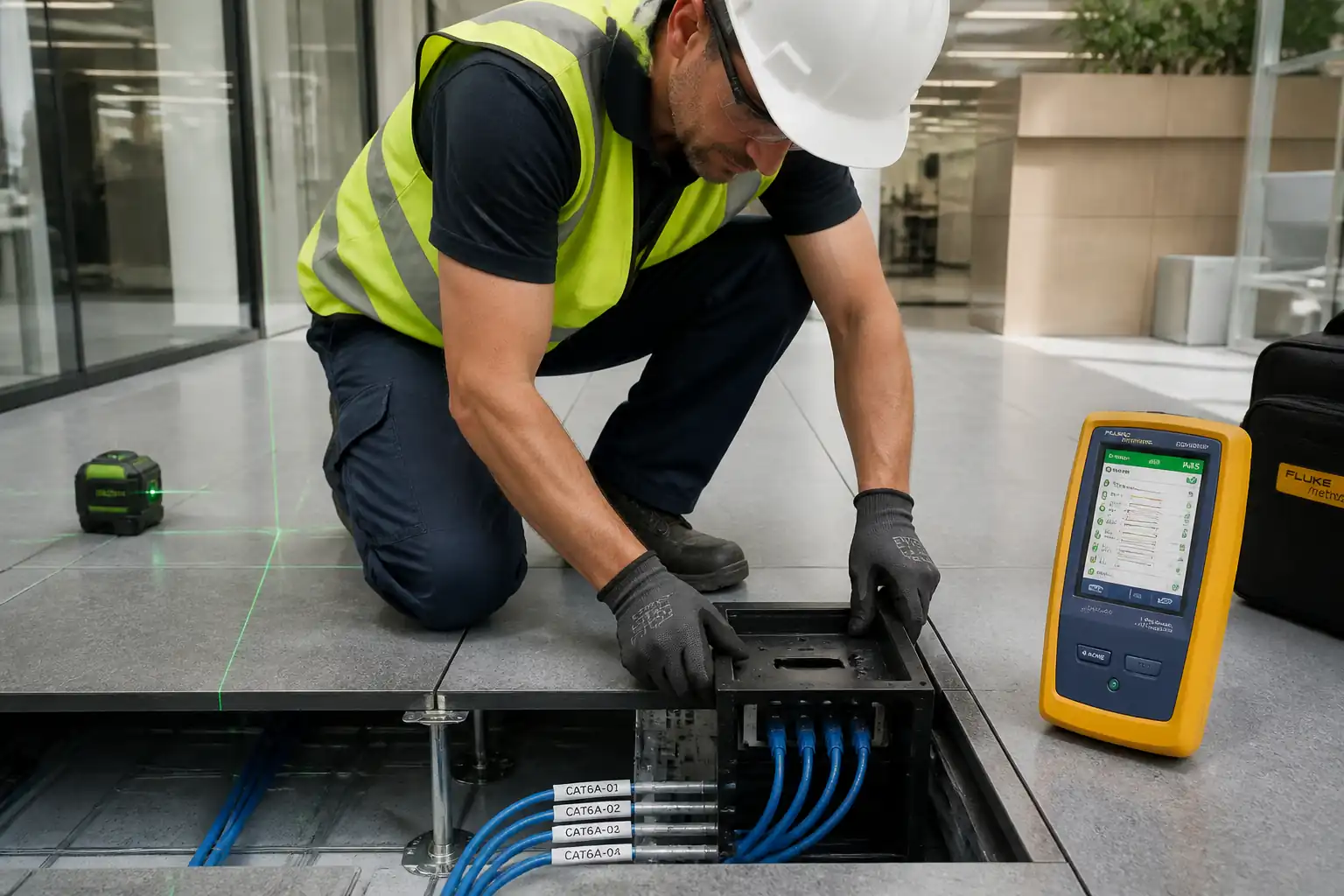
This method statement covers the complete installation of low-current floor boxes and data outlets for structured cabling (e.g., Cat 6/Cat 6A) in areas with raised access floors or screeds. It includes box coordination and setting-out, conduit routing and entries, cable pulling, termination, labeling, protection of installed works, alignment checks, certification testing, QA/QC inspections, and handover documentation.
Inclusions
- Coordination of floor box locations with architectural finishes, furniture layouts, and raised floor/screed build-up.
- Installation of recessed floor box bodies and lids; segregation from power within combination boxes.
- Conduit and pathway works from horizontal cabling pathways or consolidation/zone boxes to floor boxes, including draw wires.
- Copper data cabling pull, termination of RJ45 jacks and faceplates per project standard (T568A or T568B), and bonding/earthing of metallic boxes.
- Labeling and administration per TIA-606.
- Protection from damage during ongoing fit-out.
- Testing: wiremap, length, continuity, and certification to the specified category/class.
- QA/QC inspections, ITP checkpoints, redlines/as-builts, and handover records.
Exclusions
- Active network equipment configuration.
- Core drilling through post-tensioned slabs or structural elements (separate method if required).
- High-voltage or power wiring within combination boxes except segregation measures.
Constraints/Assumptions
- Penetrations through fire-rated elements will be sealed with approved firestop systems by certified installers.
- All dimensions and tolerances to be verified against project specifications and approved shop drawings [Verify per project specifications].
References
| Document Type | Reference / Number | Revision | Notes |
|---|---|---|---|
| Standard | ISO/IEC 11801-1 | Class E/E A performance (Cat 6/6A) as specified [Verify]. | |
| Standard | ANSI/TIA-606-D (or latest) [Verify] | Labeling scheme, records, identifiers. | |
| Standard | ANSI/TIA-568.2-D; IEC 61935-1; ANSI/TIA-1152-A | Field tester accuracy Level 2G (Cat 6A) or better. | |
| Standard | ANSI/TIA-569-D | Conduit fill ≤40%, max two 90° bends between pull points; pull box at ≤30 m [Verify]. | |
| Standard | EN 50174-2; IEC 60364-5-52 | Separation from LV power; bonding of metallic pathways and enclosures. | |
| Standard | BS EN 61386 series | uPVC or steel conduits; fittings, bend radii, mechanical strength. | |
| Standard | IEC 60364 (or BS 7671/NEC as applicable) [Verify] | Earthing/bonding of metallic floor boxes and conduits. | |
| Standard | ASTM E814/UL 1479 or EN 1366-3 [Verify] | Use tested systems for rating equivalency. | |
| Standard | BS EN 12825; PSA MOB PF2 (guidance) [Verify] | Coordination with tile/pedestal layout and load ratings. |
Responsibilities
| Role | Responsibility | Name / Party |
|---|---|---|
| Project Manager | Approve shop drawings/methods; ensure interfaces resolved; authorize WIRs. | Main Contractor |
| Engineer | Verify locations, tolerances, separations; raise RFIs; maintain ITP. | Main Contractor |
| Supervisor | Ensure correct termination scheme, protection, and labeling. | Main Contractor |
| QA/QC | WIR submissions; verify tests; maintain NCR/CAR system. | Main Contractor |
| HSE | Verify controls for cutting, noise, silica dust, manual handling, live services. | Main Contractor |
| Engineer | Update coordination model, export set-out drawings. | Main Contractor |
| Consultant | Approve locations, compliance with specifications. | Client/Consultant |
| Technicians | Follow manufacturer instructions, standards, and supervision. | Main Contractor/Subcontractor |
Resources
| Resource Type | Description | Quantity | Remarks |
|---|---|---|---|
| Manpower | Cable pulling, termination, box installation | 1 team per 30 outlets/day [Verify] | |
| Manpower | Certification testing and reporting | 1 person per tester | |
| Manpower | HSE oversight, permits, inspections | As per HSE plan [Verify] | |
| Manpower | Quality checks, ITP compliance | Shared |
Materials
| Material | Specification / Grade | Quantity | Remarks |
|---|---|---|---|
| Floor box | Compliant with BS EN 60670/BS EN 50085 (where applicable) [Verify] | ||
| Connectors | ANSI/TIA-568.2-D; ISO/IEC 11801-1 compliant | ||
| UTP/FTP cable | Cat 6 or Cat 6A per specification; flame rating per IEC 60332/UL 1666 [Verify] | ||
| Conduit | BS EN 61386 series; fill ≤40% [Verify] | ||
| Labels | ANSI/TIA-606-D | ||
| Firestop | UL 1479/ASTM E814 or EN 1366-3 | ||
| Earthing | IEC 60364/BS 7671 [Verify] | ||
| Protection | Project finish protection standard [Verify] |
Equipment
| Equipment | Capacity / Type | Quantity | Inspection Required |
|---|---|---|---|
| DSX series or equivalent | |||
| Self-leveling laser | |||
| Core/oscillating tool | |||
| Hand bender, fish tape | |||
| Adjustable torque | |||
| Assorted |
Prerequisites
- Approved IFC drawings, coordinated shop drawings/BIM model showing tile grid, furniture, equipment locations, and box types.
- Method Statement and ITP approved; Risk Assessment and Task Briefing conducted.
- Material submittals approved for floor boxes, jacks, cables, conduits, firestop, labels.
- PTW/permits as applicable: hot works (if cutting), work in raised floor void, live services permit [Verify per project HSE plan and local regulations].
- Calibration certificates (≤12 months old) for test instruments; label printer consumables available.
- Site survey completed: verify screed thickness, raised floor height, underfloor services, and no conflicts with pedestals/ducts.
- Underground/underfloor service scan where drilling/cutting is needed (avoid post-tension tendons and embedded services) [Verify].
- Delivery inspection for damages; storage in dry, clean environment; temperature and bend radius per manufacturer.
- Mock-up (if required) approved for representative finish and performance.
- Coordination meeting held with architect/MEP to confirm datum and tolerance at transitions and to define segregation from power.
- Fire strategy confirmed for any penetrations; approved systems and installers available.
Method Sequence
| Step | Activity | Description | Responsibility | Inspection / Hold Point |
|---|---|---|---|---|
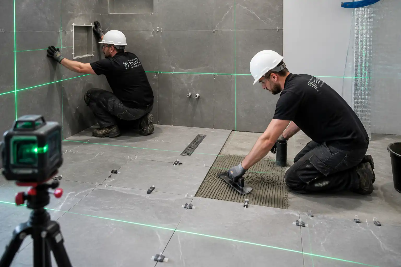
| 1 | Set-out and Coordination | Mark box locations from grid lines with laser. Confirm with furniture layouts and access floor tile grid. | Site Engineer / ELV Supervisor | Hold point: location approval before cutting/embedding |
| 2A | Floor Box – Raised Access Floor | Cut opening in floor tile per template; fit box support frame; route flexible conduit to opening; ensure segregation from power in combined boxes. | ELV Technicians | Surveillance |
| 2B | Floor Box – Screed Installation | Fix recessed box body to structural slab before screed pour using adjustable mounts/shims; cap openings; protect threads. | ELV Technicians | Witness during fixing and pre-pour |
| 3 | Conduit/Pathway Installation | Install conduits from zone box/containment to floor box. Provide bushings/grommets; install draw wire; limit bends and length. | ELV Technicians | Surveillance |
| 4 | Cable Pulling | Pull horizontal cables through conduits/void using draw wire; avoid kinks; maintain bend radius; no lubricant unless approved. | ELV Technicians | Surveillance |
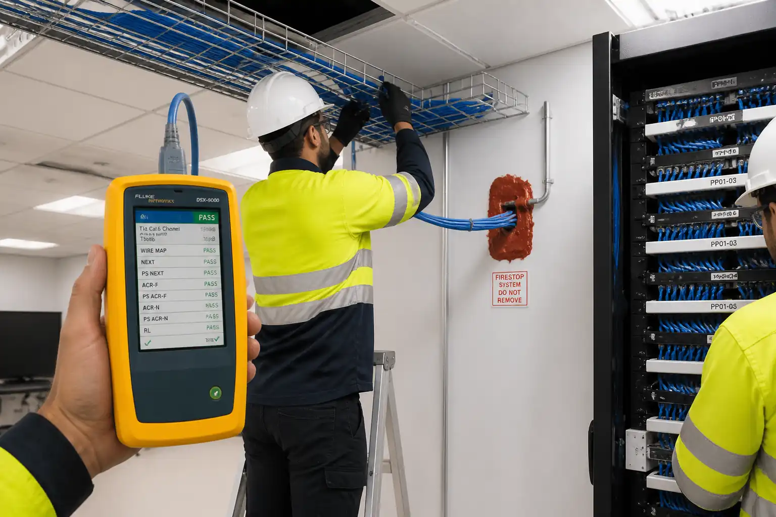
| 5 | Termination at Floor Box | Strip minimal sheath; terminate RJ45 jacks per T568A/B; maintain pair twist to within 13 mm; install faceplate and box lid. | ELV Technicians | Witness |
| 6 | Labeling and Administration | Label outlets, cables, and patch panels per TIA-606; update records and floor plans. | ELV Supervisor | Surveillance |
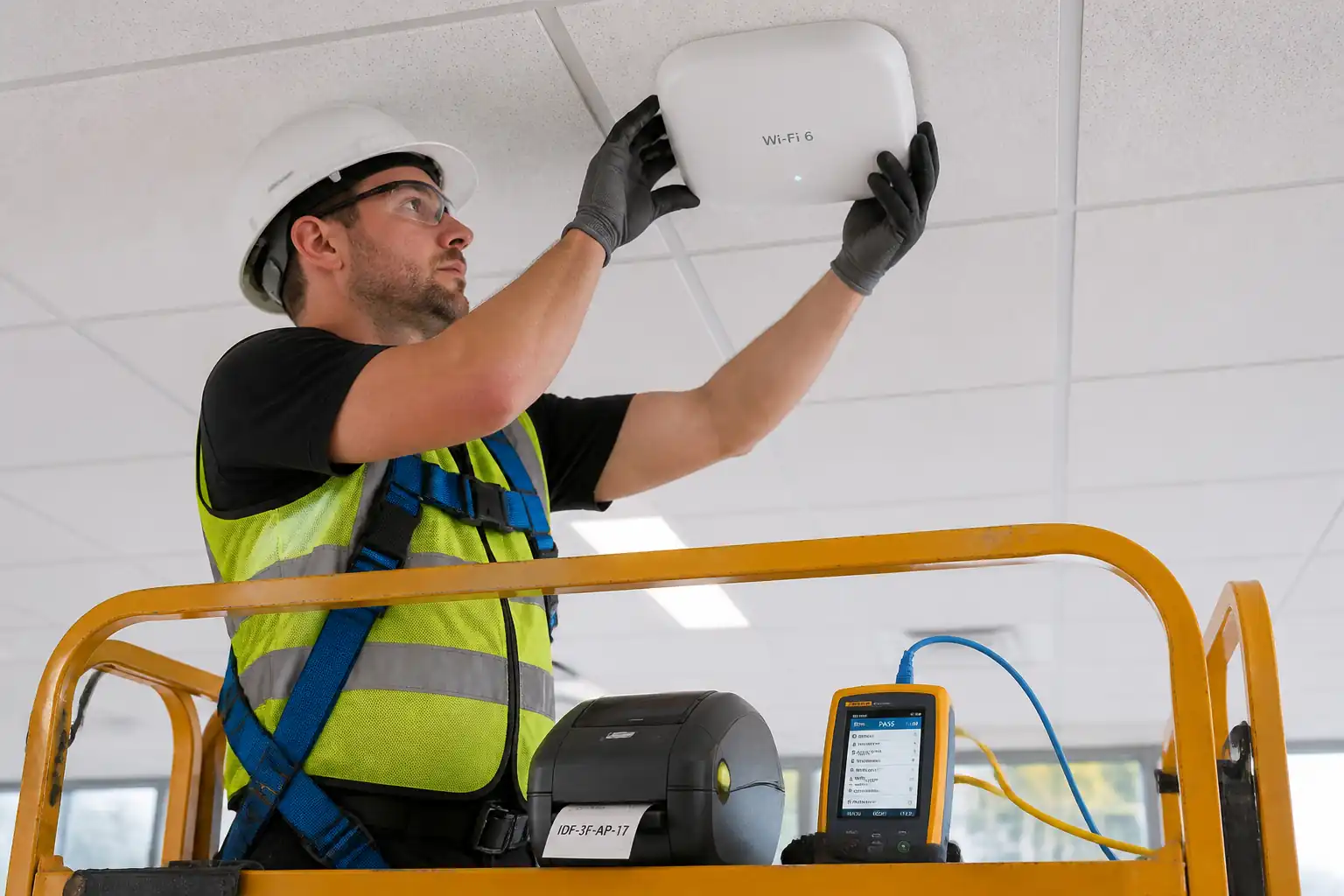
| 7 | Testing – Verification and Certification | Perform wiremap and length; then certify Permanent Link or Channel as specified using calibrated tester. | Tester/Commissioning Tech | Witness by QA/QC |
| 8 | Protection and Handover Preparation | Fit temporary protective covers; clean; prevent ingress of debris/paint; lock lids where required. | ELV Supervisor | Surveillance |
| 9 | Final Inspection and Handover | Offer for inspection with full documentation; demonstrate representative sample functionality. | QA/QC with Client/Consultant | Hold point: final acceptance |
Safety Controls
Task-specific Hazards and Controls
- Hazard: Cutting/drilling in raised floor tiles or screed
- Likely consequence: Silica dust inhalation, lacerations, hitting embedded services
- Engineering/procedural control: Use dust-extraction tools with HEPA vac; pre-scan area for services; mark no-cut zones; wet-cut only if compatible with finishes; use guards
- Required PPE: Safety glasses/face shield, cut-resistant gloves, FFP2/FFP3 respirator, hearing protection
- Collective preventive measure: Local exhaust ventilation and barriers; exclusion zone signage
-
Inspection/permit/supervision: Hot works/cutting permit as applicable; HSE officer to verify extraction setup [Verify per project HSE plan and local regulations]
-
Hazard: Work in raised floor void/open tiles
- Likely consequence: Trips/falls, stepping into openings, dropped objects
- Engineering/procedural control: Lift minimum tiles; edge protectors; temporary covers secured; tool lanyards; keep walkways clear
- Required PPE: Safety footwear with toe protection, gloves
- Collective preventive measure: Barricade open areas; housekeeping checks
-
Inspection/permit/supervision: Supervisor to inspect hourly; record in daily HSE log
-
Hazard: Electrical contact with adjacent live power circuits in combination boxes
- Likely consequence: Electric shock, burns
- Engineering/procedural control: Isolate/lockout power where feasible; maintain segregation barriers; verify de-energized with meter; use insulated tools
- Required PPE: Insulated gloves (rated), eye protection
- Collective preventive measure: Clear labeling of compartments; lock-off devices
-
Inspection/permit/supervision: Electrical PTW/LOTO; competent person oversight
-
Hazard: Manual handling of tiles and boxes
- Likely consequence: Musculoskeletal injuries, crushed fingers
- Engineering/procedural control: Use tile lifters; team lifts; limit lift weight <25 kg per person [Verify]; plan lift path
- Required PPE: Gloves with grip, safety footwear
- Collective preventive measure: Mechanical aids/trolleys
-
Inspection/permit/supervision: Supervisor to brief safe lifting; spot checks
-
Hazard: Sharp edges/burrs on cutouts and metal boxes
- Likely consequence: Cuts/lacerations, cable sheath damage
- Engineering/procedural control: Deburr edges; fit grommets/bushings; inspect before cable pull
- Required PPE: Cut-resistant gloves, long sleeves
- Collective preventive measure: Standardize grommet kits in task boxes
-
Inspection/permit/supervision: QA/QC to verify before pulling
-
Hazard: Noise and vibration from power tools
- Likely consequence: Hearing loss, nuisance to occupants
- Engineering/procedural control: Low-noise blades, schedule noisy works off-hours, maintain tools
- Required PPE: Hearing protection (SNR per tool rating)
- Collective preventive measure: Acoustic screens where appropriate
-
Inspection/permit/supervision: Noise monitoring to project limits [Verify]
-
Hazard: Firestop sealant/adhesive chemicals
- Likely consequence: Skin/eye irritation, VOC exposure
- Engineering/procedural control: Review SDS; ensure ventilation; use low-VOC products
- Required PPE: Nitrile gloves, goggles
- Collective preventive measure: Spill kits on site
-
Inspection/permit/supervision: Chemical handling permit if required; SDS available at workface
-
Hazard: Working around other trades/congested areas
- Likely consequence: Strikes, collisions, damage to finished work
- Engineering/procedural control: Daily coordination meetings; designated material zones; protect finished surfaces
- Required PPE: Standard site PPE
- Collective preventive measure: Access control and traffic plans
-
Inspection/permit/supervision: Supervisor coordination sign-off daily
-
Hazard: Use of ladders/step stools for access to zone boxes
- Likely consequence: Falls from low height
- Engineering/procedural control: Use podium steps/approved ladders; three-point contact; inspect before use
- Required PPE: Non-slip footwear
- Collective preventive measure: Prefer mobile platforms
- Inspection/permit/supervision: Ladder inspection tags; weekly inspections
Environmental Controls
- Dust control: Use on-tool extraction with HEPA filters; vacuum (not broom) cleanup; damp-wipe in sensitive areas.
- Noise: Plan noisy activities outside occupied hours; comply with site noise limits; use low-noise blades and maintain tools.
- Waste management: Segregate cable offcuts (WEEE), metal scrap, conduit pieces; recycle where possible; dispose per licensed contractor with waste transfer notes.
- Chemical/VOC management: Select low-VOC sealants/adhesives; store in sealed containers; provide ventilation; prevent spills; keep SDS on site.
- Protection of finishes: Use temporary floor protection and box caps; prohibit painting over box lids; immediate cleanup of adhesives/paints.
- Energy/resource use: Optimize test sequences; switch off idle tools; use LED task lighting.
- Water/effluent: Avoid wet-cutting where it risks slurry discharge; if wet methods used, contain and dispose of slurry as per environmental plan.
- Complaints management: Maintain an environmental log; respond to dust/noise complaints within 24 hours [Verify per project environmental plan].
QA/QC
Quality Objectives
- Install floor boxes and outlets in the exact coordinated locations, flush with finishes, damage-free, and compliant with the specified performance class.
Inspection and Testing
- Material receipt: Verify make, model, category rating, batch numbers, and approvals.
- In-process: Check conduit fill, bend radius, separations, deburred entries, grommets, bonding continuity.
- Termination: Verify color code, pair untwist, shield bonding, torque.
- Testing: 100% certification testing using calibrated Level 2G or better tester to the specified standard and link model (Permanent Link or Channel).
Acceptance Criteria
- Location tolerance: ±5 mm from coordinates; lid flushness ±2 mm with finished floor; lids open/close freely; no trip/rocking.
- Pathway: Conduit fill ≤40%; bends and pull lengths per TIA-569-D [Verify].
- Segregation: Maintain minimum separation from LV power per EN 50174-2/TIA-569-D; use partitions or screened cables if closer [Verify].
- Termination: Pair untwist ≤13 mm; no nicked conductors; shield continuity per manufacturer; bonding continuity <0.5 Ω to earth [Verify].
- Test results: PASS per ISO/IEC 11801 Class E/EA or ANSI/TIA-568.2-D Cat 6/6A as specified; length limits met; store native files.
Documentation
- WIRs with photos, checklists, and approvals at defined hold/witness points.
- Calibration certificates (≤12 months old) for testers and torque tools [Verify].
- As-built drawings with outlet IDs, cable routes, and box schedules.
- Test reports (native + PDF/CSV), label schedules, O&M manuals, warranties.
Nonconformance
- Record NCR for any deviation; apply corrective action (re-termination, replace damaged cable/box); re-test and re-offer for inspection.
Training/Competency
- Use manufacturer-certified installers for the selected cabling system where required to maintain system warranty.
Attachments
- Manufacturer installation manuals for floor boxes, jacks, and cables.
- Approved shop drawings and coordinated BIM views with outlet schedules.
- Risk Assessment/Method Statement (RAMS) and Task Briefing records.
- WIR templates and in-process inspection checklists.
- Test equipment calibration certificates.
- Sample test report (approved format) and label schedule template.
- Firestop system approvals and details (if any penetrations).
- O&M manual template, warranty letters, and as-built drawing format.
This content is a read-only public reference. Download or customize to get an editable version.
ITP preview
The first inspection activities from the linked ITP for Method Statement – Low-Current Floor Box and Data Outlet Installation:
| Activity | Inspection / Test | Acceptance Criteria | Responsibility | Record |
|---|---|---|---|---|
| Pre-installation Coordination/Set-out | Verify location vs. drawings; check obstructions; confirm separation strategy | Locations marked within ±5 mm; conflict-free; hold point released | Site Engineer / QA/QC / Consultant (Witness) | WIR, marked-up drawings, photos |
| Floor Box Fixing (Raised floor or Screed) | Level/flush check; compartment segregation; protection prior to pour (if screed) | Flushness ±2 mm; secure fixing; segregation barriers in place; openings protected | QA/QC (Witness) / Consultant (Hold) | WIR, checklists, photos |
| Conduit/Pathway Inspection (Before Concealment) | Bend count; fill factor; bushings/grommets; separations; bonding continuity (if metallic) | Fill ≤40%; ≤2×90° bends; grommets fitted; separation per EN 50174-2/TIA-569-D; bonding continuous | QA/QC (Witness) | Concealed work inspection form, photos |
Showing 3 of 8 inspection activities. View full ITP →
Related Inspection and Test Plan
An Inspection and Test Plan (ITP) is available for Method Statement – Low-Current Floor Box and Data Outlet Installation. The ITP defines the inspection activities, acceptance criteria, hold and witness points, responsible parties, and records required to verify the work described in this method statement.
View the Method Statement – Low-Current Floor Box and Data Outlet Installation ITP →Frequently asked questions
Continue with related Quollnet resources connected to this method statement.