Method Statement: Cement–Sand Floor Screed Works – Method Statement
AI-assisted method statement with matching ITP, PDF download, and Excel export.
More than a static template
Unlike a downloadable Word or PDF template, this method statement is an AI-assisted editable starting point connected directly to a matching Inspection and Test Plan. Every section is structured, project-adaptable, and ready to export.
- AI-assisted drafting — Customize every section with AI for your specific project scope.
- Linked ITP — A matching inspection and test plan is generated alongside the method statement.
- Multiple export formats — Download as a formatted PDF or editable Excel spreadsheet.
- Editable starting point, not a final document — Review, verify, and adjust all content against your project requirements before use.
Static template vs. Quollnet workflow
| Feature | Static template | Quollnet |
|---|---|---|
| Project-specific content | Manual fill-in required | AI-assisted customization |
| Linked ITP | Separate document, no link | Matching ITP included |
| Export formats | Usually PDF only | PDF and Excel |
| Structured sections | Free-form layout | 13 standardized sections |
| Saved to your account | Local file only | Cloud-saved, reusable |
| Content accuracy | You verify everything | AI-assisted, you still verify |
| Cost | Often free but time-intensive | Free to customize and download |
What you can customize
When you save this method statement to your account, every section becomes editable. The following 13 sections are included:
- Scope — Defines the activity and its boundaries.
- References — Standards, specifications, and drawings.
- Responsibilities — Roles and accountabilities.
- Resources — Labour, plant, and equipment summary.
- Materials — Materials and compliance requirements.
- Equipment — Tools and equipment details.
- Prerequisites — Hold points and pre-conditions.
- Method sequence — Step-by-step construction sequence.
- Safety controls — HSE risk controls and PPE.
- Environmental controls — Environmental mitigation measures.
- QA/QC — Quality inspection and test requirements.
- ITP — Inspection and Test Plan table (has its own page).
- Attachments — Referenced drawings and documentation.
Why this method statement is used
This method statement is used to define and communicate the approved procedure for carrying out method statement: cement–sand floor screed works on site. It ensures the work is planned in advance, the correct resources and controls are in place, and all personnel understand responsibilities, sequence, quality requirements, and safety controls before work begins. It aligns site execution with the documented scope and acceptance expectations.
Who uses this method statement
This method statement is used by contractors, site supervisors, project engineers, QA/QC engineers, HSE officers, consultants, and client representatives. It serves as a shared reference for planning, execution, supervision, inspection, and approval of the activity on site.
When it is prepared and submitted
The method statement is prepared before the work activity starts and submitted as part of the pre-construction documentation package for review and approval.
Who reviews or approves it
The method statement is usually submitted to the client representative, consultant, resident engineer, or project management consultant for review and approval before the work commences.
Important approval note
This method statement is an AI-assisted editable starting point, not a pre-approved document. Before use on any project, all content must be reviewed and approved by the relevant parties (superintendent, principal contractor, or client representative) in accordance with your contract and project quality plan.
For example: if your specification requires a departure from a referenced standard, that departure must be documented and approved separately — this method statement will not capture that automatically. Always verify against your applicable drawings, specifications, and regulatory requirements.
Method statement content
Scope
Description
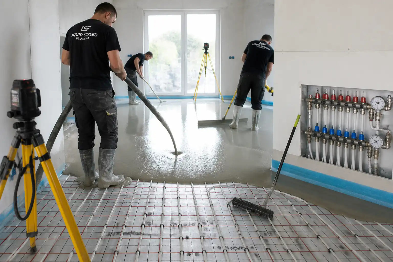
This method statement covers materials, workmanship, sequence, QA/QC, HSE, and ITP requirements for cement–sand floor screed works in commercial and residential areas. It includes substrate preparation; datum/benchmarks; bonding methods (bonded, unbonded, floating, heated); screed mixing, placement, compaction, finishing; thickness and level control; curing; flatness and levelness verification; moisture testing prior to floor finishes; and handover records.
Areas
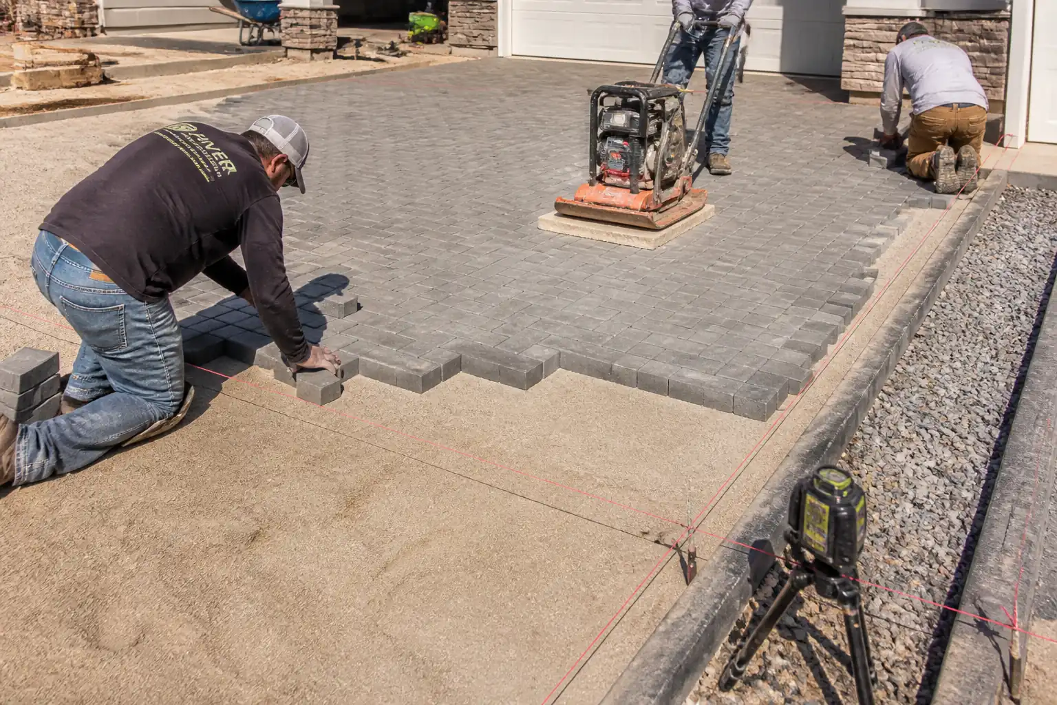
- All internal floor areas scheduled to receive cement–sand screed prior to floor finishes (tiles, resilient floorings, timber, carpet, resin).
Exclusions
- Structural concrete slabs and toppings not designated as screed.
- Calcium sulphate/anhydrite screeds (separate method required).
Objectives
- Achieve specified surface regularity (SR class), thickness, strength, bond (for bonded screeds), moisture condition for floor finish compatibility, and documented compliance through ITP, inspections, tests, and records.
References
| Document Type | Reference / Number | Revision | Notes |
|---|---|---|---|
| Standard | BS 8204-1 | Latest [Verify per project specifications] | |
| Standard | BS EN 13813 | Latest [Verify per project specifications] | |
| Standard | BS 8203 / ASTM F2170 / ASTM F1869 | Latest [Verify per project specifications] | |
| Standard | BS EN 197-1 / ASTM C150 | Latest [Verify per project specifications] | |
| Standard | BS EN 13139 / ASTM C33 | Latest [Verify per project specifications] | |
| Standard | BS EN 1008 | Latest [Verify per project specifications] | |
| Standard | BS EN 13892-2/-8 etc. | Latest [Verify per project specifications] | |
| Standard (Guidance) | ACI 302.1R | Latest [Verify per project specifications] | Used as guidance where aligned with BS 8204. |
| TDS | As supplied | Current | [Verify per project specifications] |
Responsibilities
| Role | Responsibility | Name / Party |
|---|---|---|
| Project Manager | PM | Contractor |
| Site Engineer | SE | Contractor |
| QA/QC Engineer | QA/QC | Contractor |
| HSE Officer | HSE | Contractor |
| Land Surveyor | Survey | Contractor |
| General Foreman | Foreman | Contractor |
| MEP Coordinator | MEP Coord. | Contractor |
| Laboratory | Lab | Independent |
| Engineer/Consultant | Employer's Rep | Employer |
Resources
| Resource Type | Description | Quantity | Remarks |
|---|---|---|---|
| Manpower | Screed gang (mixing, pumping, leveling, finishing) | 6 persons | |
| Manpower | Setting out and QA levels | 1 person |
Materials
| Material | Specification / Grade | Quantity | Remarks |
|---|---|---|---|
| Cement | CEM I 42.5N min [Verify] | [As per BOQ] | |
| Sand | Zone 2–3 [Verify] | [As per BOQ] | |
| Water | Clean | As required | |
| SBR/Epoxy | Per TDS [Verify] | [As required] | |
| PE membrane | 1200 gauge [Verify] | [As per drawings] | |
| Edge strip | Compressible, 50–100 mm high [Verify] | [As required] | |
| Profiles | Height= screed depth | [As per drawings] | |
| PP fibers | 6–12 mm length [Verify] | [As specified] | |
| Curing | Non-staining | As required |
Equipment
| Equipment | Capacity / Type | Quantity | Inspection Required |
|---|---|---|---|
| Mixer | ≥200 L [Verify] | 1–2 | |
| Pump | 1 | ||
| Laser | 1 | ||
| Hand tools | As required | ||
| As required | |||
| Sets as required | |||
| 1 |
Prerequisites
Approvals & Coordination
- Approved method statement, ITP, mix design, and material submittals.
- Confirm screed type per area: bonded, unbonded, floating, heated (UFH).
- Drawings marked with movement joints, bay layout, and finished floor levels (FFL).
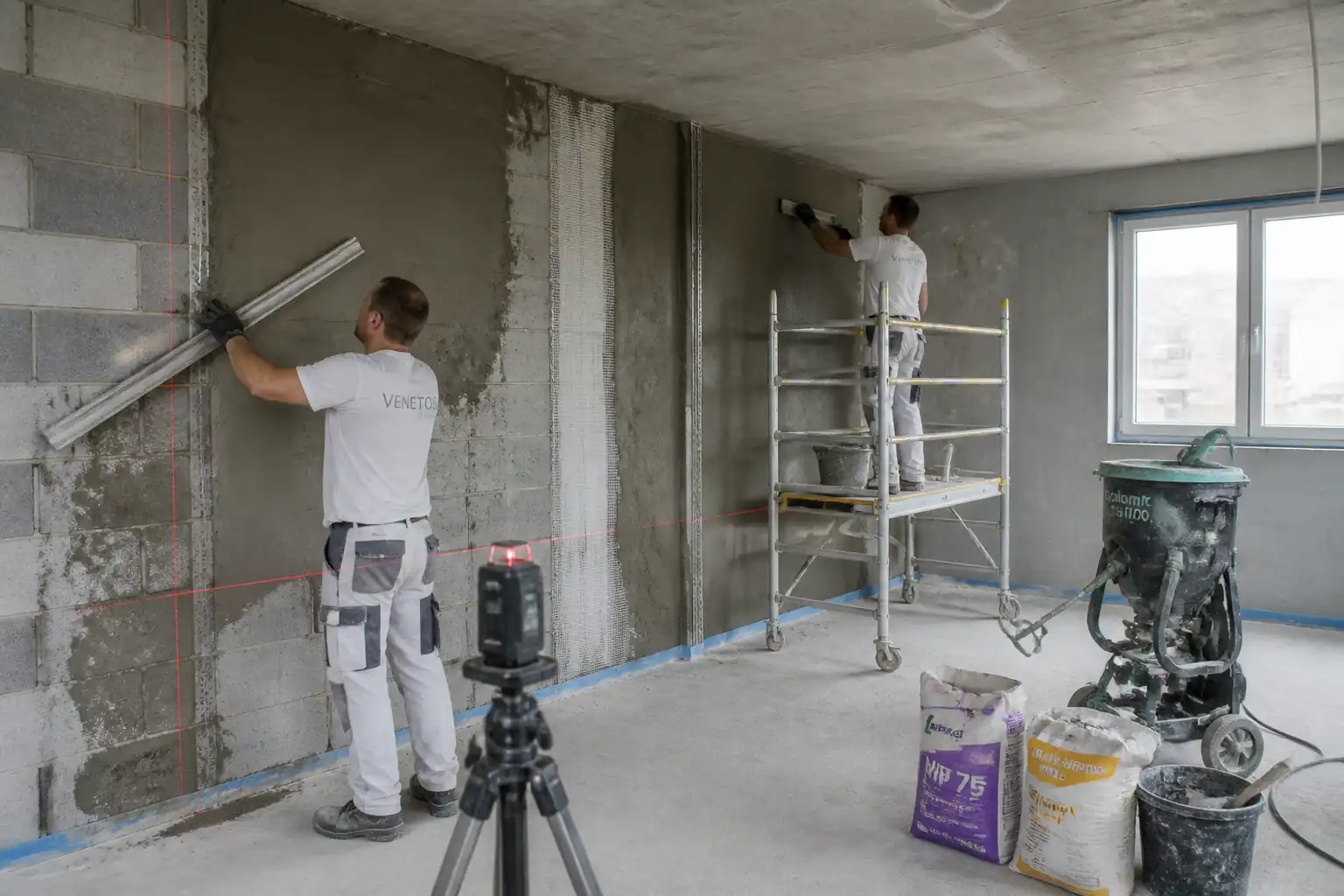
Substrate Readiness
- Structural slab cured and load-bearing; surface free of laitance, curing compounds, oil, dust, paint, and weak layers.
- Existing cracks assessed; structural cracks treated per Engineer’s instruction.
- MEP embedded services fixed and inspected; floor penetrations sealed.
- For bonded screed: surface prepared to obtain a mechanical profile (CSP 3–5) by shot blasting/scabbling; vacuum cleaned.
Environmental & Site Conditions
- Ambient/substrate temperature 10–30°C; avoid draughts and direct heat. [Verify per project specifications]
- Adequate lighting and ventilation without causing rapid drying.
- Weatherproof building envelope or temporary protection in place.
Moisture & DPM
- Assess base slab moisture. If moisture risk exists, install specified DPM or epoxy moisture barrier compatible with finishes. [Verify]
Benchmarks & Survey
- Establish primary datum (±0.000) and transfer to each room. Create benchmark marks on walls/columns at ≤10 m spacing.
- Determine screed thickness from FFL minus finish build-up; confirm minimums by type:
- Bonded: 25–40 mm typical minimum [Verify].
- Unbonded (on slip membrane): 50–70 mm typical minimum [Verify].
- Floating over insulation: 65 mm domestic, 75 mm commercial; with UFH: typically 65–75 mm over pipes or total depth ≥75–90 mm [Verify].
UFH (If Applicable)
- Heating pipes/cables fixed, pressure-tested (e.g., 6 bar for 24 h, no loss) and maintained under pressure during screeding. [Verify]
Permits & HSE
- Task-specific risk assessment, permits to work (hot work not expected; verify for cutting/grinding), COSHH/SDS for cement and primers.
Mock-Up
- Construct a minimum 4–6 m² mock-up to demonstrate mixing, placing, finishing, curing, and achieve SR class; obtain approval before full works.
Method Sequence
| Step | Activity | Description | Responsibility | Inspection / Hold Point |
|---|---|---|---|---|
| 1 | Material receipt and storage | Receive cement, sand, primers; verify certificates. Store cement off-ground, sand on clean pad, protect from contamination. | Foreman/QA | Delivery inspection |
| 2 | Pre-start survey & services verification | Check area dimensions, FFL, set out bay/joint layout; confirm MEP clearances and UFH readiness. | SE/MEP Coord. | IR: Pre-pour clearance (HP1) |
| 3 | Substrate preparation | Shot blast or scarify to CSP 3–5; grind high spots; vacuum to dust-free surface; treat cracks and fill holes with polymer-modified repair mortar; honour structural joints. | Foreman/QA | Surface profile check |
| 4 | Install membranes/insulation/edge strips (as applicable) | Unbonded: lay PE slip membrane with 150 mm laps, taped. Floating: install insulation boards flat and tight; install perimeter edge strip continuously at walls/columns; protect penetrations. | SE/Foreman | IR: Membrane/insulation (HP2) |
| 5 | Set benchmarks, pins, and screed rails | Transfer datum; set level pins/rails with laser at 1.5–2.5 m grid or as bay size requires; verify thickness vs design; allow for falls where specified. | Survey/SE | Level check |
| 6 | Prepare bonding coat (bonded screed only) | Apply SBR-cement slurry (e.g., 1:1 SBR:water; cement to form brushable slurry) or epoxy primer per TDS. Work wet-on-wet: place screed while bonding coat is still tacky/wet. | SE/QA | IR: Bonding method (HP3) |
| 7 | Mixing screed | Semi-dry mix in forced-action mixer. Typical ratio: cement:sand = 1:3.5–1:4.5 by weight; W/C ~0.40–0.50 to achieve earth-moist consistency; fibers if specified. Mix 2–4 minutes to uniform color. | Pump Op/Foreman | Batch control |
| 8 | Transport and placement | Deliver promptly to workface; spread between rails; compact by tamping/rodding; work from far end to exit; maintain UFH under pressure. | Crew | Workface supervision |
| 9 | Striking off and levelling | Use straightedge to strike to rails/pins; close surface with wood float; form day joints at planned locations; install joint profiles where detailed. | Crew/SE | Flatness checks |
| 10 | Finishing | After initial set, steel trowel to closed finish if required; avoid over-trowelling that traps water. Provide surface key where bonded toppings specified. | Crew | Visual |
| 11 | Curing and protection | Immediately cover with polythene sheeting overlapped/taped for 7 days minimum or apply approved curing compound compatible with adhesives. Prevent draughts and rapid drying; restrict foot traffic for 24–48 h; heavy loads after ≥7 days [Verify]. | Foreman/QA | Daily curing check |
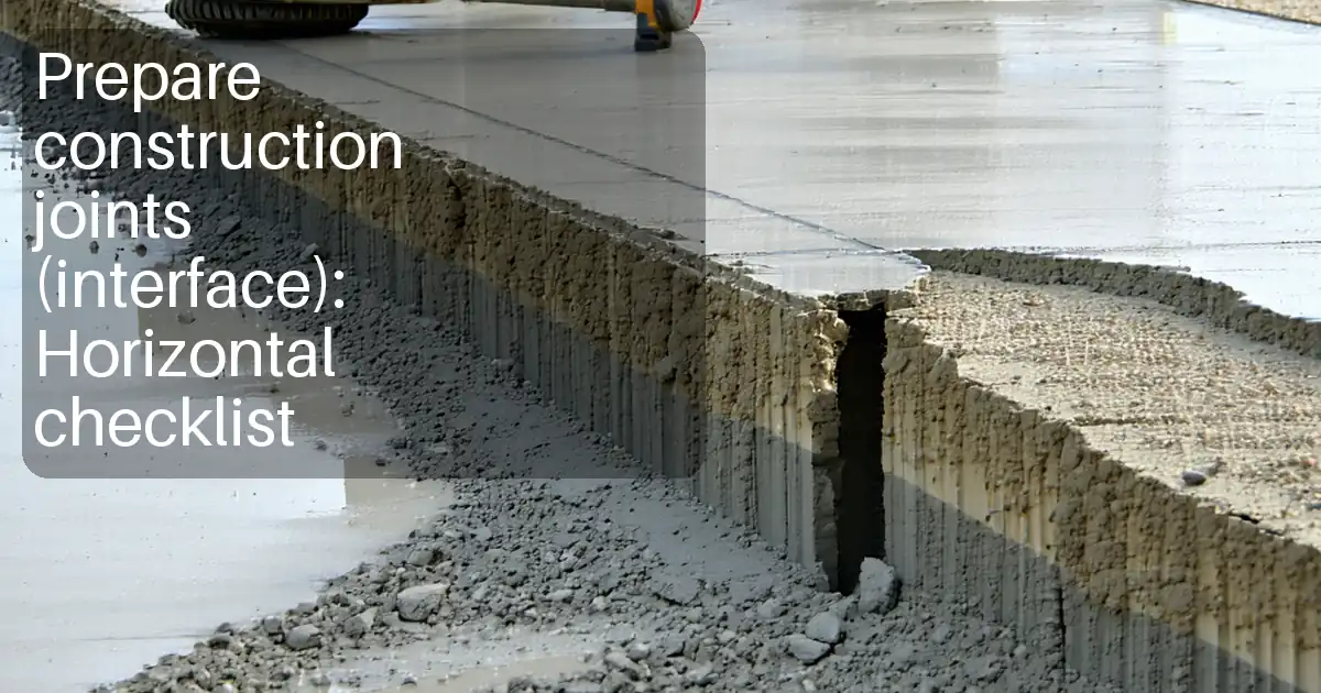
| 12 | Saw cuts / movement joints (if specified) | Introduce saw cuts at planned locations once sufficient strength achieved (typically 12–24 h). Depth ~1/3 screed thickness; maintain joint alignment through finishes. | SE/Foreman | Joint layout verification |
| 13 | Initial QA measurements | Check thickness using depth probes at not less than 1 point/20 m²; flatness with 2 m straightedge; levels vs datum; record results. | QA/QC/Survey | IR: Post-place checks (WP) |
| 14 | Strength/bond testing (if specified) | Prepare cubes/prisms per EN 13892-2 (e.g., 40×40×160 mm) 1 set/200 m² [Verify]; pull-off adhesion tests for bonded screeds at ≥14–28 days. | QA/QC/Lab | Sample witness (WP) |
| 15 | Drying and moisture testing before finishes | Allow drying (rule of thumb 1 mm/day to 40 mm then slower; confirm by test). Conduct in-situ RH per BS 8203/ASTM F2170 or MVER per ASTM F1869 at rate ≥3 tests/room or 1/100 m² min [Verify]. | QA/QC | IR: Moisture test (HP4) |
| 16 | Remedials if required | Grind high spots; fill low areas with polymer-modified repair mortar; re-test flatness/moisture as applicable; record NCR/CAR closure. | SE/QA | Re-inspection |
| 17 | Handover and protection | Install protection boards where heavy traffic continues; issue final acceptance package before flooring works. | PM/QA | Final IR (HP5) |
Safety Controls
Task-Specific Hazards and Controls
- Hazard: Silica dust from grinding/shot blasting and sand handling.
- Likely consequence: Respiratory irritation, silicosis over chronic exposure.
- Engineering/procedural control: Use on-tool extraction (M-class/H-class vacuums), wet methods where feasible, sealed waste containers; limit dry sweeping; dedicated cutting/grinding zone.
- Required PPE: P3 respirator, safety glasses/goggles, gloves.
- Collective preventive measure: Local exhaust ventilation and enclosure; dust suppression.
-
Inspection/permit/supervision: HSE inspections; equipment PAT and extraction performance checks. [Verify per project HSE plan and local regulations]
-
Hazard: Wet cement/alkali burns and skin/eye contact with primers/epoxies.
- Likely consequence: Chemical burns, dermatitis, eye injury.
- Engineering/procedural control: Provide running water/eye wash; use long-handled tools; follow COSHH/SDS; prohibit kneeling in wet screed without knee protection covers.
- Required PPE: Alkali-resistant gloves, long sleeves, waterproof boots, knee pads, face shield when handling chemicals.
- Collective preventive measure: Chemical storage cabinets, spill kits.
-
Inspection/permit/supervision: COSHH assessments; chemical handling training; SDS on site.
-
Hazard: Manual handling of cement bags and rails/straightedges.
- Likely consequence: Musculoskeletal injury.
- Engineering/procedural control: Use mechanical aids (trolleys), split loads, team lifts, bag lifters.
- Required PPE: Gloves, safety boots.
- Collective preventive measure: Task rotation, ergonomic training.
-
Inspection/permit/supervision: Supervisor checks; manual handling training records.
-
Hazard: Trip/fall on uneven surfaces, pins/rails, open edges/penetrations.
- Likely consequence: Sprains, lacerations, falls from height (if near shafts/edges).
- Engineering/procedural control: Good housekeeping; barricade edges and penetrations; mark pins/rails with high-vis tape; defined walkways.
- Required PPE: Safety boots, hi-vis vest, hard hat.
- Collective preventive measure: Edge protection, covers with fixings.
-
Inspection/permit/supervision: Daily HSE walkdowns; permit to work near edges if at height.
-
Hazard: Noise/vibration from prep equipment and mixers.
- Likely consequence: Hearing loss, HAVS.
- Engineering/procedural control: Select low-noise equipment; maintain tools; limit exposure time.
- Required PPE: Hearing protection (SNR per measured levels), anti-vibration gloves.
- Collective preventive measure: Noise zoning and signage.
-
Inspection/permit/supervision: Noise assessments; HAVS monitoring.
-
Hazard: Pump hose rupture or whip during pumping.
- Likely consequence: Impact injury, splashes.
- Engineering/procedural control: Pressure-rated hoses, whip checks, secure couplings, exclusion zones at discharge.
- Required PPE: Eye/face protection, gloves, boots.
- Collective preventive measure: Physical barriers and spotter.
-
Inspection/permit/supervision: Pre-use hose inspection; pump operator authorization.
-
Hazard: Working over UFH pipes/cables.
- Likely consequence: Puncture/leak leading to rework and flooding.
- Engineering/procedural control: Use protective walk boards; maintain pressure test; no sharp tools near pipes; marked pipe runs.
- Required PPE: Standard site PPE.
- Collective preventive measure: Area control and signage.
-
Inspection/permit/supervision: UFH pressure gauge monitored; MEP supervision.
-
Hazard: use of epoxy primers/solvents (if specified).
- Likely consequence: Sensitization, inhalation hazard.
- Engineering/procedural control: Use low-VOC products where possible; ensure ventilation without draughts over fresh screed; follow mixing ratios; no ignition sources.
- Required PPE: Respirator (A2P3 filters if needed), chemical gloves, goggles.
- Collective preventive measure: Ventilation fans with filters.
- Inspection/permit/supervision: Hot work permit if ignition risk; gas monitoring if enclosed spaces. [Verify per project HSE plan and local regulations]
Emergency Preparedness
- Eye wash and clean water available within 10 m of mixing zone; spill kits for chemical leaks; first aider on site; access/egress kept clear for emergency response.
Environmental Controls
Key Environmental Aspects and Controls
- Cement washout and alkaline runoff
- Impact: Soil/water alkalinity increase, fish kills.
- Control: Designated lined washout area >15 m from drains/watercourses; collect and dispose via licensed contractor; never discharge to storm drains.
-
Inspection: Daily by Foreman; records of disposal.
-
Dust and fine particulate from sand handling and surface prep
- Impact: Air quality, nuisance to neighbors.
- Control: Covered sand stockpiles; water misting when feasible; on-tool extraction with H-class vacuums; sealed waste bags.
-
Inspection: HSE/dust log; corrective actions recorded.
-
Noise from mixers/pumps and grinders
- Impact: Nuisance to occupants/neighbors.
- Control: Work hour restrictions, acoustic shrouds where practical, equipment maintenance, scheduling noisy works during permitted times.
-
Inspection: Noise monitoring as required.
-
Packaging and general construction waste
- Impact: Landfill burden.
- Control: Segregate bags, plastic, metal profiles; recycle where possible; keep waste skips covered.
-
Inspection: Weekly waste audits.
-
VOCs/odors from primers/curing compounds (if used)
- Impact: Indoor air quality.
- Control: Low-VOC selections; ventilate; maintain SDS; avoid over-application.
-
Inspection: Supervisor checks; material usage logs.
-
Energy and water use
- Impact: Resource consumption.
- Control: Shut down idle plant; use metered water; leak checks on hoses.
- Inspection: Daily checklist; meter readings if applicable.
[Verify per project HSE plan and local regulations]
QA/QC
Inspection and Testing
- Hold Points (HP):
- HP1: Pre-start substrate/MEP readiness and FFL confirmation.
- HP2: Membrane/insulation/edge strip installation (unbonded/floating).
- HP3: Bonding coat application (bonded) prior to screeding.
- HP4: Moisture testing prior to floor finishes.
-
HP5: Final acceptance/area handover.
-
Witness Points (WP):
- Mixing and placement start-up checks; initial SR/level checks; sampling.
Testing Regime [Verify per project specifications]
- Thickness: Min 1 check/20 m², not less than 3 per room.
- Surface Regularity: 2 m straightedge in orthogonal directions; at least 10 readings/room or 1/20 m².
- Levels: Laser level vs datum; grid ≤10 m.
- Strength (if specified): EN 13892-2 compressive/flexural; 1 set/200 m² per mix/day.
- Bond (bonded screed): Pull-off adhesion per EN 13892-8; min 3 tests/area or 1/100 m².
- Moisture before finishes: In-situ RH per BS 8203/ASTM F2170 or MVER per ASTM F1869; minimum 3 tests/room or 1/100 m².
Acceptance Criteria [Verify per project specifications]
- SR Class: SR1 ≤3 mm; SR2 ≤5 mm; SR3 ≤10 mm (max deviation under 2 m straightedge, BS 8204-1).
- Level Tolerance: Typically ±5 mm over 10 m unless specified otherwise.
- Thickness: Not less than design minimum by screed type; no negative tolerance below minimum; local highs/lows ≤ tolerance for SR class.
- Strength Class: Not less than EN 13813 class specified (e.g., CT-C25-F4 typical for sand–cement screed).
- Bond (bonded screed): Pull-off ≥1.0 N/mm² typical.
- Moisture for finishes: RH ≤75% for resilient/wood (unless adhesive/TDS states otherwise); tiles may accept higher with suitable adhesive/system.
Calibration and Records
- Calibrations: Laser levels, pull-off tester, RH probes – valid calibration certificates.
- Records: IRs at HP/WP, batch logs, QA check sheets, test reports, NCR/CAR, as-built level survey, curing logs, MSDS/SDS, training/permit records.
Defects and Remedials
- High spots: Mechanical grinding.
- Low spots: Polymer-modified repair mortar; re-test SR.
- Cracks: Assess cause; epoxy injection or cut-and-fill bands; reinstate joints if restrained movement identified.
Attachments
- Mix design sheet with approved ratios and materials.
- Mock-up approval record with SR measurements and finish notes.
- Bay layout and jointing drawings referencing structural joints.
- Manufacturer technical datasheets (SBR/epoxy primers, curing compounds, joint profiles, fibers) and SDS.
- Calibration certificates (laser, RH probes, pull-off tester).
- QA forms: Thickness log, SR check sheet, Level survey template, Curing log, Moisture test log.
- HSE documents: Task risk assessment, COSHH assessments, permits, toolbox talk records.
- Handover checklist and final acceptance form.
This content is a read-only public reference. Download or customize to get an editable version.
ITP preview
The first inspection activities from the linked ITP for Method Statement: Cement–Sand Floor Screed Works:
| Activity | Inspection / Test | Acceptance Criteria | Responsibility | Record |
|---|---|---|---|---|
| Pre-start substrate and FFL verification (HP1) | Visual, drawings review, level survey | Area released; FFL confirmed; services clear | SE/QA/Engineer | IR HP1, level log |
| Surface preparation quality | Cleanliness check; pull-off spot test (bonded) | Clean, sound, CSP 3–5; pull-off ≥1.0 N/mm² (bonded) [Verify] | QA/Engineer | Prep log, photos, test report |
| Membranes/insulation/edge strip installation (HP2) | Visual; lap/tape check; level | Continuous membrane; 150 mm laps; no punctures; insulation level; perimeter strip continuous | SE/Engineer | IR HP2 |
Showing 3 of 12 inspection activities. View full ITP →
Related Inspection and Test Plan
An Inspection and Test Plan (ITP) is available for Method Statement: Cement–Sand Floor Screed Works. The ITP defines the inspection activities, acceptance criteria, hold and witness points, responsible parties, and records required to verify the work described in this method statement.
View the Method Statement: Cement–Sand Floor Screed Works ITP →Frequently asked questions
Continue with related Quollnet resources connected to this method statement.