Method Statement: Screed Installation Over Underfloor Heating (UFH) Systems – Method Statement
AI-assisted method statement with matching ITP, PDF download, and Excel export.
More than a static template
Unlike a downloadable Word or PDF template, this method statement is an AI-assisted editable starting point connected directly to a matching Inspection and Test Plan. Every section is structured, project-adaptable, and ready to export.
- AI-assisted drafting — Customize every section with AI for your specific project scope.
- Linked ITP — A matching inspection and test plan is generated alongside the method statement.
- Multiple export formats — Download as a formatted PDF or editable Excel spreadsheet.
- Editable starting point, not a final document — Review, verify, and adjust all content against your project requirements before use.
Static template vs. Quollnet workflow
| Feature | Static template | Quollnet |
|---|---|---|
| Project-specific content | Manual fill-in required | AI-assisted customization |
| Linked ITP | Separate document, no link | Matching ITP included |
| Export formats | Usually PDF only | PDF and Excel |
| Structured sections | Free-form layout | 13 standardized sections |
| Saved to your account | Local file only | Cloud-saved, reusable |
| Content accuracy | You verify everything | AI-assisted, you still verify |
| Cost | Often free but time-intensive | Free to customize and download |
What you can customize
When you save this method statement to your account, every section becomes editable. The following 13 sections are included:
- Scope — Defines the activity and its boundaries.
- References — Standards, specifications, and drawings.
- Responsibilities — Roles and accountabilities.
- Resources — Labour, plant, and equipment summary.
- Materials — Materials and compliance requirements.
- Equipment — Tools and equipment details.
- Prerequisites — Hold points and pre-conditions.
- Method sequence — Step-by-step construction sequence.
- Safety controls — HSE risk controls and PPE.
- Environmental controls — Environmental mitigation measures.
- QA/QC — Quality inspection and test requirements.
- ITP — Inspection and Test Plan table (has its own page).
- Attachments — Referenced drawings and documentation.
Why this method statement is used
This method statement is used to define and communicate the approved procedure for carrying out method statement: screed installation over underfloor heating (ufh) systems on site. It ensures the work is planned in advance, the correct resources and controls are in place, and all personnel understand responsibilities, sequence, quality requirements, and safety controls before work begins. It aligns site execution with the documented scope and acceptance expectations.
Who uses this method statement
This method statement is used by contractors, site supervisors, project engineers, QA/QC engineers, HSE officers, consultants, and client representatives. It serves as a shared reference for planning, execution, supervision, inspection, and approval of the activity on site.
When it is prepared and submitted
The method statement is prepared before the work activity starts and submitted as part of the pre-construction documentation package for review and approval.
Who reviews or approves it
The method statement is usually submitted to the client representative, consultant, resident engineer, or project management consultant for review and approval before the work commences.
Important approval note
This method statement is an AI-assisted editable starting point, not a pre-approved document. Before use on any project, all content must be reviewed and approved by the relevant parties (superintendent, principal contractor, or client representative) in accordance with your contract and project quality plan.
For example: if your specification requires a departure from a referenced standard, that departure must be documented and approved separately — this method statement will not capture that automatically. Always verify against your applicable drawings, specifications, and regulatory requirements.
Method statement content
Scope
Works Included
- Supply and installation coordination of cement-sand or flowing screed over water-based UFH pipe circuits on insulation (floating) or unbonded build-ups.
- UFH circuit protection, pressure testing and monitoring prior to, during, and post screeding.
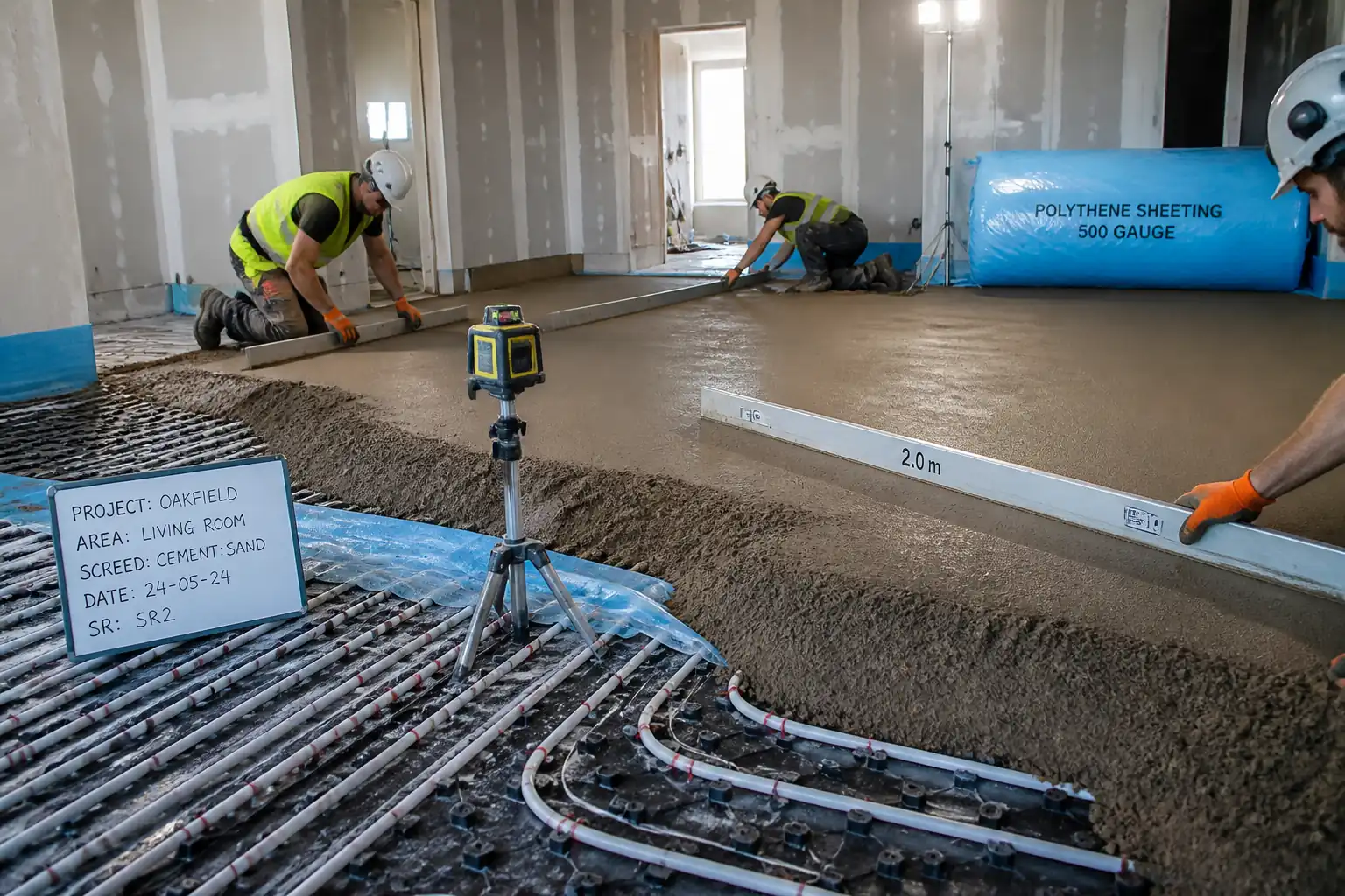
- Screed mix verification, delivery/pumping/placement, levelling/compaction/finishing, bay/joint formation, and curing/early-age protection.
- Thermal movement detailing: perimeter isolation, day joints, movement joints, and crack control (fibres/mesh where specified).
- QA/QC inspections including surface regularity (SR), screed integrity (BRE Drop Hammer), moisture/RH tests before floor finishes, and record keeping.
- UFH initial heat-up and commissioning coordination after screed curing, including temperature ramping and logging.
Exclusions
- Structural concrete slabs and toppings, DPM beneath sub-base, and final floor finishes installation.
- Electrical UFH systems and acoustic test certifications (unless specified separately).
Key Performance Requirements
- Maintain specified cover above UFH pipes: typically ≥25 mm for traditional cement-sand; ≥30–40 mm for calcium sulfate flowing screed [Verify per project specifications].
- Bay size and aspect ratio in heated floors typically ≤40 m², longest side ≤8 m, aspect ratio ≤2:1; movement joints at thresholds/column lines/changes in construction [Verify].
- Surface regularity per BS 8204: SR1 (3 mm), SR2 (5 mm), or SR3 (10 mm) under a 2 m straightedge, as specified [Verify].
- Moisture at time of finishes: cement-sand ≤75% RH (in-situ) or ≤2.0 CM%; calcium sulfate ≤0.5 CM% for tiles/stone and ≤0.3 CM% for timber/elastic finishes [Verify].
- BRE Screed Tester maximum indentation to category required: e.g., Cat A ≤2.0 mm; Cat B ≤3.0 mm; Cat C ≤4.0 mm [Verify].
References
| Document Type | Reference / Number | Revision | Notes |
|---|---|---|---|
| BS 8204 (series) - Screeds, bases and in-situ floorings; incl. BS 8204-1 and -7 | Surface regularity classes SR1/SR2/SR3; construction types; testing incl. BRE Screed Tester [Verify edition]. | ||
| BS EN 1264 (parts 1–5) - Water based surface embedded heating and cooling systems | Design, installation, testing, controls, and commissioning of UFH. | ||
| BS EN 13813 - Screed material and floor screeds – Materials and requirements | Classification (CT, CA, C, F), compressive/flexural classes, flow properties for flowing screeds. | ||
| BS 8203 / BS 5325 - In-situ floor finishes over screeds (RH criteria) | ≤75% RH in-situ per BS 8203 for resilient finishes unless a suitable surface DPM is used [Verify]. | ||
| BRE Digest/BR 292 method (In-situ crushing resistance) referenced by BS 8204 | BRE Drop Hammer test for screed soundness and category A/B/C acceptance [Verify]. | ||
| ASTM C230/C230M (Flow table), EN flow ring methods (as applicable to product) | For proprietary flowing screeds, use manufacturer’s EN-based test; do not mix standards. [Verify product TDS]. | ||
| ISO 9001, ISO 14001, ISO 45001 (management systems) | For contractors’ management controls [Verify certification]. |
Responsibilities
| Role | Responsibility | Name / Party |
|---|---|---|
| PM | Main Contractor Project Manager | Main Contractor |
| SE | Site Engineer | Main Contractor |
| QA/QC | QA/QC Engineer | Main Contractor |
| HSE | HSE Manager | Main Contractor |
| UFH Subcontractor | UFH Specialist Subcontractor | MEP |
| Screed Subcontractor | Screeding Subcontractor | Specialist |
| Engineer | Engineer / Employer’s Representative | Client |
Resources
| Resource Type | Description | Quantity | Remarks |
|---|---|---|---|
| Personnel | Screed gang (4–6) including pump operator, levellers, finisher | Per pour day [Verify] | |
| Personnel | UFH specialist for pressure testing and monitoring during pour | 1–2 | |
| Personnel | Setting-out engineer with laser level/optical level | 1 | |
| Personnel | QA/QC inspector for checks and documentation | 1 |
Materials
| Material | Specification / Grade | Quantity | Remarks |
|---|---|---|---|
| Cement-sand screed | |||
| CA flowing screed | |||
| Cementitious flowing screed | |||
| Perimeter strip | |||
| Polythene VCL | |||
| Thermal insulation | |||
| Mesh/fibres | |||
| Curing compound / sheeting |
Equipment
| Equipment | Capacity / Type | Quantity | Inspection Required |
|---|---|---|---|
| Putzmeister/Equivalent | 1 | ||
| Pan mixer / Silo | 1 | ||
| Rotary laser | 1 set | ||
| As required | |||
| As required | |||
| 1 set | |||
| 1 set |
Prerequisites
- Approved shop drawings showing UFH zones, manifold locations, screed build-ups, movement/perimeter joint layouts, and thresholds.
- ITP approved with defined hold/witness points; inspection request schedule issued to Engineer.
- Confirm substrate readiness: structural slab strength achieved; DPM installed (if specified); levels surveyed with datum benchmarks established and recorded.
- Environmental conditions: ambient and substrate temperature 5–30°C; building weather-tight; ventilation plan available; dewatering not required in area; no risk of freezing [Verify].
- UFH installation completed, labelled by circuit, connected to manifold; pressure test equipment available; UFH Specialist present for test and monitoring.
- Materials approvals (DoP/CE, TDS, safety data sheets). Calibrations current for measuring equipment.
- Access, edge forms, perimeter strips, and bay/movement joint locations marked on drawings and site.
- HSE: RAMS briefed; permits to work as required [Verify per project HSE plan and local regulations].
- Mock-up/trial bay (if specified) completed and accepted prior to production pour.
Method Sequence
| Step | Activity | Description | Responsibility | Inspection / Hold Point |
|---|---|---|---|---|
| 1 | Substrate verification and preparation | Inspect slab for flatness, debris, laitance; repair high/low spots as per spec; ensure clean, dry surface. Install DPM/VCL if specified. | Site Engineer / Screed Subcontractor | Visual and level survey |
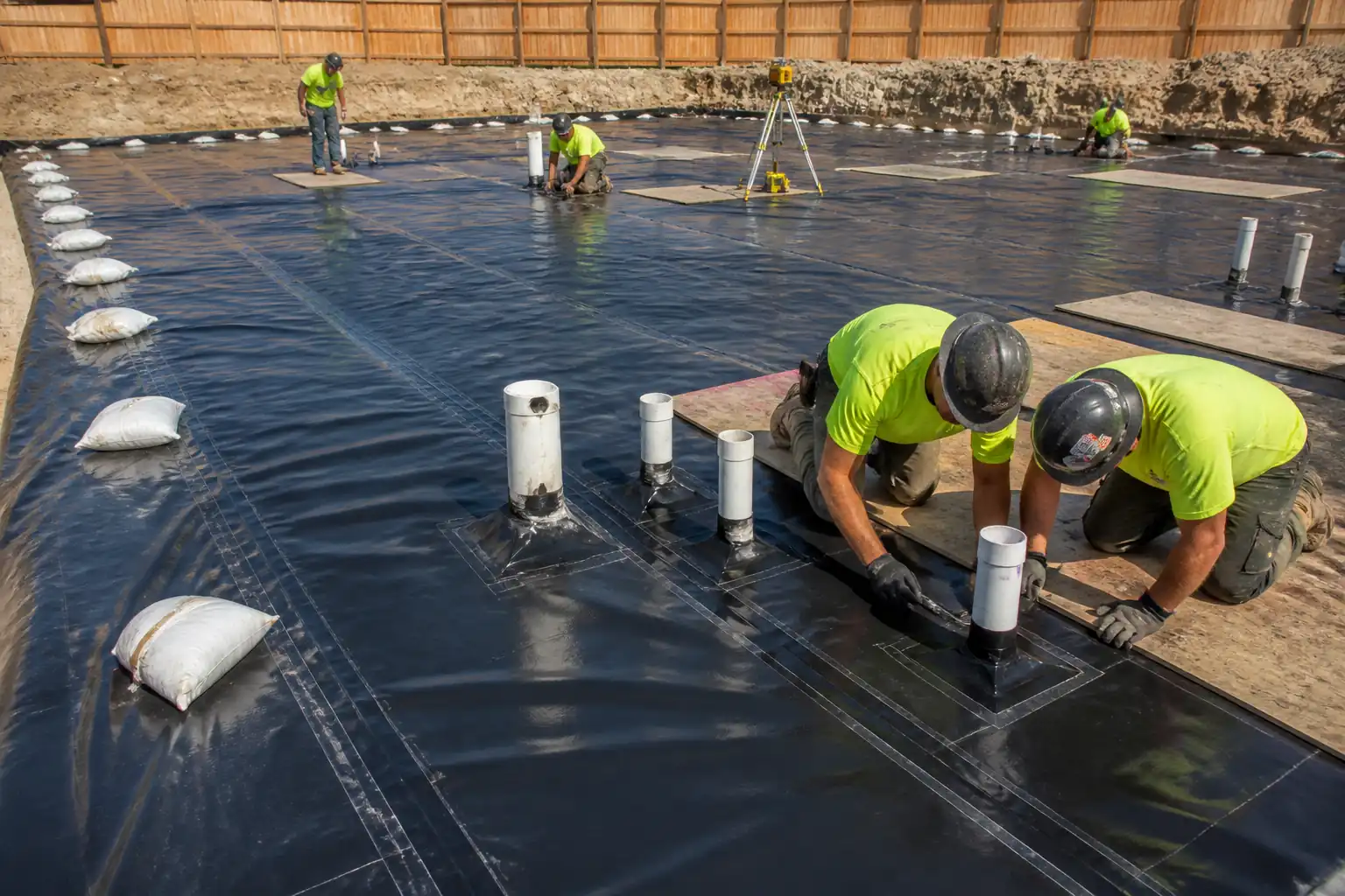
| 2 | Insulation & VCL installation | Lay insulation boards tightly butted; stagger joints; infill gaps; install slip membrane/VCL with 150 mm taped laps turned up at edges. | Screed Subcontractor | Visual; check laps/turn-ups |
| 3 | Perimeter isolation strip | Install compressible perimeter strip around all walls, columns, and fixed upstands; height above screed finish. | Screed Subcontractor | Visual |
| 4 | UFH pipe installation | Fix pipes to insulation/rails per spacing and layout; protect against flotation; label circuits; connect to manifold. | UFH Subcontractor | Visual; fixing check |
| 5 | UFH hydrostatic pressure test (pre-pour) | Fill and purge air; test each circuit. Typical: 1.5× operating pressure (not <4 bar) for ≥2 h or 6 bar for 24 h per EN 1264/supplier [Verify]. Log pressure and ambient temperature. | UFH Subcontractor / QA-QC | Gauge reading; data log |
| 6 | Pipe protection & access control | Install walk boards/kneeling boards; cordon area; prohibit sharp tools; maintain test pressure during all works. | Screed Subcontractor / UFH Subcontractor | Supervision |
| 7 | Level control setup | Set laser datum; install levelling tripods/pins or rail screed guides to required FFL minus finish allowance. | Site Engineer / Screed Subcontractor | Level check |
| 8 | Screed receipt and workability check | Verify delivery tickets; conduct flow/spread (flowing screed) or consistency check (traditional). Adjust only per TDS; no water addition beyond limits. | QA-QC / Screed Foreman | On-site test |
| 9 | Placement and levelling | Place from furthest corner towards exit; avoid walking on exposed pipes; for flowing screed, pour in lanes and dapple in two directions; for traditional, compact and rule off to pins; integrate reinforcement if specified (upper third). | Screed Subcontractor | In-process check |
| 10 | Movement/day joints | Form day joints at breaks; install movement joints as per drawings at thresholds, bay limits, and structural joints; ensure continuity of perimeter isolation. | Screed Subcontractor | Visual; dimensions |
| 11 | Initial protection and curing | Maintain UFH under test pressure; do not heat. For traditional: cure with polythene or curing compound; protect 24–72 h from draughts/traffic. For flowing CA: prevent rapid drying; provide controlled ventilation after initial set per supplier TDS. | Screed Subcontractor | Daily |
| 12 | Early-age checks (24–72 h) | Check surface hardness, damage, contamination; restrict loads; remove laitance on CA screeds by light sanding after sufficient strength per TDS. | QA-QC / Screed Subcontractor | Visual; scratch check |
| 13 | Initial heat-up/commissioning of UFH | After curing: Cement-sand typically ≥21 days; CA typically ≥7 days [Verify]. Raise flow temp to ~25°C for 3 days, then increase by ≈5°C/day to design temp (≤50–55°C) for 4 days; then reduce to off. Record flow/return temps. | UFH Subcontractor / MEP | Monitor temps/pressures |
| 14 | Surface regularity (SR) check | After sufficient hardening, check SR class with 2 m straightedge and documented grid. | QA-QC | Measurement |
| 15 | Screed integrity (BRE) | Test with BRE Screed Tester at representative locations (min 3 per room or 1/20 m², whichever greater) once screed is adequately cured. | QA-QC / Independent Tester | Witness |
| 16 | Moisture condition before finishes | Measure in-situ RH (hood box) and/or CM moisture. Repeat after commissioning cycle if required. | QA-QC / Finishes Contractor | Measurement |
| 17 | Handover records | Compile approvals, test certificates, as-builts, and maintenance requirements; include UFH zone drawings and valve settings. | Main Contractor / UFH / Screed Subcontractor | Document review |
Health, Safety and Environment (HSE) - Safety Controls
Task-Specific Hazards and Controls
1) Pressurised UFH circuit rupture
- Consequence: Fluid ejection, slips, flooding, pipe damage, eye injury.
- Engineering/Procedural Control: Hydrostatic test with calibrated gauges; maintain pressure during pour; protect manifolds; emergency isolation valves accessible; use walk boards; no mechanical fixing into floor after UFH installation.
- PPE: Eye protection, waterproof safety boots, gloves.
- Collective Measure: Exclusion zones and signage around manifolds; drip trays under manifolds.
- Inspection/Permit/Supervision: Test certificate reviewed; gauges logged every 2 h; supervision by UFH specialist; PTW if interfacing with live services [Verify per project HSE plan and local regulations].
2) Pump line burst / hose whip
- Consequence: Impact injury, chemical burns, slips.
- Control: Rated hoses with whip checks; pressure relief before disconnection; secure couplings; line routing plan; barricades at discharge.
- PPE: Hard hat, goggles/face shield, chemical-resistant gloves, safety boots.
- Collective: Physical barriers; emergency stop accessible at pump.
- Inspection/Permit/Supervision: Pre-use inspection checklist; operator competency certification.
3) Cement/anhydrite exposure (alkaline/irritant)
- Consequence: Skin/eye burns, dermatitis, respiratory irritation.
- Control: Use long sleeves, impervious gloves; avoid direct skin contact; provide wash stations; use mixers with dust suppression; follow SDS.
- PPE: Chemical-resistant gloves, goggles, long sleeves, waterproof trousers, suitable mask (P2/P3) when dry powder handled.
- Collective: Local exhaust ventilation or wet suppression at mixing; closed transfer where possible.
- Inspection/Permit/Supervision: SDS on site; COSHH assessment; HSE walkdowns.
4) Slips, trips, and falls on wet screed/UFH pipes
- Consequence: Sprains, fractures, damaged works.
- Control: Define access routes; walk boards over UFH; keep hoses tidy; clean spills immediately; anti-slip grates at entries.
- PPE: Slip-resistant boots, gloves.
- Collective: Barrier tape and attendants at access points.
- Inspection/Permit/Supervision: Housekeeping inspections every 2 h during pour.
5) Manual handling of bags/boards/hoses
- Consequence: Musculoskeletal injury.
- Control: Use mechanical aids (trolleys, hoists); team lifts; limit bag weights; staging near point of use.
- PPE: Gloves, boots.
- Collective: Task rotation and breaks.
- Inspection/Permit/Supervision: Manual handling assessment; supervisor monitoring.
6) Noise and vibration from pumps/mixers
- Consequence: Hearing loss, hand-arm vibration exposure.
- Control: Position equipment away from enclosed spaces; maintain equipment; limit exposure time.
- PPE: Hearing protection.
- Collective: Acoustic screens where needed; signage.
- Inspection/Permit/Supervision: Noise assessment; HAVS records.
7) Cutting/forming joints (if saw-cutting applicable)
- Consequence: Silica dust inhalation, lacerations, eye injury.
- Control: Wet-cut methods or on-tool extraction; trained operators only; blades guarded.
- PPE: Eye/face protection, gloves, P3 mask, hearing protection.
- Collective: Local extraction; water supply; exclusion zone.
- Inspection/Permit/Supervision: Hot works or cutting permit if required; equipment pre-use checks.
8) Confined/poorly ventilated rooms
- Consequence: Accumulation of dust/vapours; heat stress.
- Control: Forced ventilation; monitor temperature/humidity; work-rest regimen; hydration.
- PPE: Lightweight PPE suited to temperature; respiratory protection when mixing.
- Collective: Portable fans/air movers.
- Inspection/Permit/Supervision: Supervisor monitors WBGT if high temperatures [Verify].
9) Working around edges, openings, or steps
- Consequence: Falls, impact injuries.
- Control: Temporary edge protection; mark level changes; covers over service openings.
- PPE: Hard hat, boots.
- Collective: Physical barriers at thresholds.
- Inspection/Permit/Supervision: Pre-pour walkdown to verify protections.
Environmental Controls
- Cementitious washout: Collect and contain wash water from pumps/mixers; no discharge to drains/soil. Use lined washout pits or IBC totes; pH-neutralize before disposal via licensed waste handler [Verify local regulations].
- Material waste: Order to take-off; segregate excess screed, packaging, and insulation offcuts; recycle where possible (clean EPS/XPS streams); record quantities.
- Dust control: Use pre-packed silos or sealed bags; on-tool extraction and misting during mixing; maintain negative pressure or forced ventilation in enclosed spaces.
- Noise: Position pumps away from receptors; limit to agreed hours; use acoustic covers where practicable.
- Spills: Spill kits at manifolds and mixing area; immediate containment and clean-up; reportable spill thresholds per site EMS [Verify].
- Energy and water: Minimize water usage in cleaning; shut down idling equipment; verify electrical PAT test for efficient motors.
- Anhydrite residues: Prevent contamination of adjacent concrete or steel drains; clean tools/boots at mat; dedicated cleaning zone to avoid sulfate transfer.
Quality Assurance / Quality Control
Controls and Records
- Mix verification: Check DoP/CE and batch tickets each delivery; confirm class (CT/CA), strength grade, and flow/consistency.
- Depth and cover: Verify cover above UFH pipes at grid points every ~10–15 m² and at edges; tolerance ±5 mm [Verify].
- Flow/consistency: Test first load and every subsequent 50 m² or 2 loads (whichever occurs first) for flowing screeds [Verify per TDS].
- SR checks: Perform after sufficient set; grid at ≤2 m spacing across rooms; classify to SR1/SR2/SR3 per BS 8204.
- BRE Screed Tester: Minimum 3 tests per room or 1 per 20 m²; increase in high-risk areas; record indentations and category.
- Moisture/RH: Test prior to finishes; frequency: minimum 1 per room up to 50 m², then 1 per each additional 50 m²; more in thick screeds or where drying risk exists.
- Non-conformance: Record NCRs for deviations (e.g., insufficient cover, SR out of tolerance, moisture high). Implement corrective actions (local grinding/filling, additional drying, surface DPM, or remedial screed) subject to Engineer approval.
- Traceability: Maintain linkage from area to batch numbers, crew, date/time, and ambient conditions.
- Calibration: Maintain calibration certificates for laser level, hygrometers, pressure gauges, and BRE tester.
- Hold/Witness Points: As indicated in ITP for UFH pre-pour test, movement/joints, commissioning start, and moisture clearance before finishes.
Attachments
- A1: Typical build-up details and movement joint locations (mark-ups)
- A2: UFH circuit layout and zoning drawings with manifold schedules
- A3: UFH Hydrostatic Pressure Test Template (24 h log)
- A4: Screed Receipt & Flow/Consistency Test Sheet
- A5: Depth/Cover Check Sheet (grid-based)
- A6: Surface Regularity (SR) Survey Sheet and grid plan
- A7: BRE Screed Tester Report Template
- A8: In-situ RH / CM Test Record
- A9: Curing Log and Ambient Conditions Sheet
- A10: UFH Commissioning Log (temperature ramp profile)
- A11: NCR/Corrective Action Form
- A12: O&M guidance for UFH and screed maintenance
This content is a read-only public reference. Download or customize to get an editable version.
ITP preview
The first inspection activities from the linked ITP for Method Statement: Screed Installation Over Underfloor Heating (UFH) Systems:
| Activity | Inspection / Test | Acceptance Criteria | Responsibility | Record |
|---|---|---|---|---|
| Pre-start documentation | Review method statement, ITP, approvals, TDS, calibrations | All approvals current; calibrations valid; permits in place | PM / QA-QC / Engineer | Pre-start checklist & approvals |
| Substrate condition | Level/cleanliness/damage survey | Acceptable substrate ready to receive insulation/VCL; defects repaired | QA-QC / Site Engineer | Substrate inspection form |
| Insulation & VCL installation | Visual and lap measurements | Tight boards; gaps <5 mm; laps ≥150 mm; upstands intact | QA-QC / Screed Subcontractor | Checklist & photos |
Showing 3 of 15 inspection activities. View full ITP →
Related Inspection and Test Plan
An Inspection and Test Plan (ITP) is available for Method Statement: Screed Installation Over Underfloor Heating (UFH) Systems. The ITP defines the inspection activities, acceptance criteria, hold and witness points, responsible parties, and records required to verify the work described in this method statement.
View the Method Statement: Screed Installation Over Underfloor Heating (UFH) Systems ITP →Frequently asked questions
Continue with related Quollnet resources connected to this method statement.