
Method Statement: Installation of Interlocking Concrete Block Paving for Walkways and Driveways – Method Statement
AI-assisted method statement with matching ITP, PDF download, and Excel export.
More than a static template
Unlike a downloadable Word or PDF template, this method statement is an AI-assisted editable starting point connected directly to a matching Inspection and Test Plan. Every section is structured, project-adaptable, and ready to export.
- AI-assisted drafting — Customize every section with AI for your specific project scope.
- Linked ITP — A matching inspection and test plan is generated alongside the method statement.
- Multiple export formats — Download as a formatted PDF or editable Excel spreadsheet.
- Editable starting point, not a final document — Review, verify, and adjust all content against your project requirements before use.
Static template vs. Quollnet workflow
| Feature | Static template | Quollnet |
|---|---|---|
| Project-specific content | Manual fill-in required | AI-assisted customization |
| Linked ITP | Separate document, no link | Matching ITP included |
| Export formats | Usually PDF only | PDF and Excel |
| Structured sections | Free-form layout | 13 standardized sections |
| Saved to your account | Local file only | Cloud-saved, reusable |
| Content accuracy | You verify everything | AI-assisted, you still verify |
| Cost | Often free but time-intensive | Free to customize and download |
What you can customize
When you save this method statement to your account, every section becomes editable. The following 13 sections are included:
- Scope — Defines the activity and its boundaries.
- References — Standards, specifications, and drawings.
- Responsibilities — Roles and accountabilities.
- Resources — Labour, plant, and equipment summary.
- Materials — Materials and compliance requirements.
- Equipment — Tools and equipment details.
- Prerequisites — Hold points and pre-conditions.
- Method sequence — Step-by-step construction sequence.
- Safety controls — HSE risk controls and PPE.
- Environmental controls — Environmental mitigation measures.
- QA/QC — Quality inspection and test requirements.
- ITP — Inspection and Test Plan table (has its own page).
- Attachments — Referenced drawings and documentation.
Why this method statement is used
This method statement is used to define and communicate the approved procedure for carrying out method statement: installation of interlocking concrete block paving for walkways and driveways on site. It ensures the work is planned in advance, the correct resources and controls are in place, and all personnel understand responsibilities, sequence, quality requirements, and safety controls before work begins. It aligns site execution with the documented scope and acceptance expectations.
Who uses this method statement
This method statement is used by contractors, site supervisors, project engineers, QA/QC engineers, HSE officers, consultants, and client representatives. It serves as a shared reference for planning, execution, supervision, inspection, and approval of the activity on site.
When it is prepared and submitted
The method statement is prepared before the work activity starts and submitted as part of the pre-construction documentation package for review and approval.
Who reviews or approves it
The method statement is usually submitted to the client representative, consultant, resident engineer, or project management consultant for review and approval before the work commences.
Important approval note
This method statement is an AI-assisted editable starting point, not a pre-approved document. Before use on any project, all content must be reviewed and approved by the relevant parties (superintendent, principal contractor, or client representative) in accordance with your contract and project quality plan.
For example: if your specification requires a departure from a referenced standard, that departure must be documented and approved separately — this method statement will not capture that automatically. Always verify against your applicable drawings, specifications, and regulatory requirements.
Method statement content
Scope
Work Included
- Survey set-out, line and level control for walkways and driveways.
- Preparation and proof-rolling of subgrade; placement and compaction of unbound granular sub-base.
- Installation of edge restraints (precast kerbs or cast in-situ concrete haunching) including bedding, alignment, and curing.
- Supply verification of bedding and jointing sand; screeding of sand bedding to tolerance.
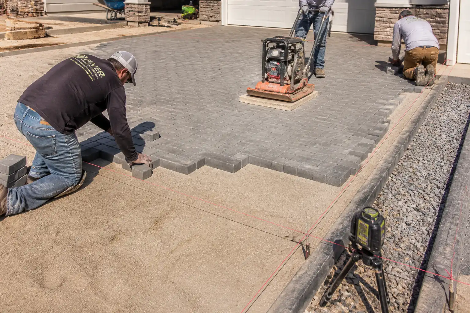
- Laying of interlocking concrete blocks in specified patterns (e.g., 45°/90° herringbone, stretcher bond) including cutting/fitting.
- Joint filling with kiln-dried sand and plate compaction of paving to refusal.
- Cleaning, protection, and handover including as-built levels and QA documentation.
Exclusions
- Subsurface drainage systems other than interface connections to existing gullies (unless noted).
- Structural base or asphalt base courses beneath sub-base.
- Illumination, landscaping, and unrelated utilities.
Performance Requirements
- Surface regularity: maximum 6 mm deviation under a 3 m straightedge [Verify per project specifications].
- Crossfall/longitudinal fall: typically 1.5–2.5% for walkways, 2–3% for driveways, unless otherwise shown [Verify].
- Joint width: nominal 2–5 mm; lippage between adjacent units ≤2 mm (≤3 mm at chamfered corners) [Verify].
- Compaction: Sub-base density per specification (typically ≥98% MDD by ASTM D1557 or ≥95% MDD by ASTM D698) [Verify].
References
| Document Type | Reference / Number | Revision | Notes |
|---|---|---|---|
| Standard | BS 7533 (notably Parts for block pavements/construction) | ||
| Standard | EN 1338 | Includes compressive strength, abrasion, freeze-thaw. | |
| Standard | EN 1340 | For precast kerbs (if used as edge restraint). | |
| Standard | EN 13242 | For Type 1/Type 2 sub-base aggregates. | |
| Standard | ASTM C936/C936M | For North American-compliant pavers. | |
| Standard | ASTM C33/C33M | ||
| Standard | ASTM D698, D1557 | ||
| Standard | ASTM D6938, D1556 | ||
| Guideline | ICPI Tech Spec 2, 4, 6 (as applicable) | [Verify per project specifications] | |
| Contract Docs | IFC Docs | Latest |
Responsibilities
| Role | Responsibility | Name / Party |
|---|---|---|
| PM | Approve method, secure permits, ensure competent resources. | Contractor |
| SE | Set-out, QA/QC, survey records, RFI management. | Contractor |
| Supervisor | Toolbox talks, workface coordination, WMS compliance. | Contractor |
| HSEO | Task-specific risk assessments, inspections, permits, monitoring. | Contractor |
| QAQC | Sampling, third-party tests, ITP sign-offs, NCRs. | Contractor |
| Surveyor | Benchmarks, level checks, line control. | Contractor |
| Trades | Follow method and supervisor instructions. | Contractor |
| Engineer | Witness/accept inspections as per ITP. | Employer/Engineer |
Resources
| Resource Type | Description | Quantity | Remarks |
|---|---|---|---|
| Labor | Skilled paver layers and general operatives | As scheduled | |
| Labor | 1 Surveyor + assistant | 1–2 | |
| Labor | Field testing and sampling | 1 | |
| Labor | Dedicated safety oversight | 1 |
Materials
| Material | Specification / Grade | Quantity | Remarks |
|---|---|---|---|
| Pavers | EN 1338 or ASTM C936 | As per BOQ | |
| Granular sub-base | EN 13242 | As per design thickness | |
| Fine aggregate | BS 7533 guidance / ASTM C33 adapted | As required | |
| Joint sand | BS 7533 / ICPI Tech Spec | As required | |
| Ready-mix or site-mix concrete | EN 206 / ACI 318 (as applicable) [Verify] | As per edge length | |
| Geotextile | EN ISO 10319/12956 [Verify] | As required |
Equipment
| Equipment | Capacity / Type | Quantity | Inspection Required |
|---|---|---|---|
| Plate compactor | 2–3 units | Yes | |
| Roller | 1 | Yes | |
| Screed kit | Sets as needed | No | |
| Level | 1 | Yes | |
| Cutter | 1–2 | Yes | |
| Mat | Per compactor | No |
Prerequisites
Approvals and Documentation
- Approved IFC drawings, pavement details, and patterns; confirmed design thicknesses and falls.
- Approved material submittals: pavers (color/thickness), bedding/jointing sand, sub-base aggregate, edge restraint details, geotextile (if any).
- Approved ITP and method statement; task-specific risk assessment and permits [Verify per project HSE plan and local regulations].
Site Readiness
- Utility clearance complete; permit-to-dig with latest utility plans and on-site detection where edges are excavated.
- Subgrade prepared to design levels and proof-rolled; unsuitable/soft spots remediated.
- Weather: Do not screed or lay bedding sand during rain, standing water, or freezing conditions; protect stockpiles from contamination.
- Access and traffic management plan in place; pedestrian segregation; lighting for night/low-light work.
Survey and Controls
- Benchmarks transferred; string lines/targets established for edges, curves, and thresholds.
- Trial panel (minimum 2 m x 2 m) approved for pattern, color, jointing, and compaction finish where specified.
Method Sequence
| Step | Activity | Description | Responsibility | Inspection / Hold Point |
|---|---|---|---|---|
| 1 | Mobilization and Briefing | Deliver materials to designated zones on firm ground; conduct toolbox talk covering pattern, tolerances, HSE, and roles. | Supervisor / HSEO | Start-up HSE inspection |
| 2 | Subgrade Proof-Roll and Preparation | Proof-roll with roller; identify pumping/soft areas; cut out and replace with compacted granular fill; trim to level and fall. | Site Engineer / QAQC | Visual + proof-roll witness |
| 3 | Sub-base Placement and Compaction | Place unbound granular sub-base in layers ≤150 mm compacted thickness; compact with roller/plate as suited; shape to design falls. | Supervisor / QAQC | Layer thickness and level checks |
| 4 | Edge Restraints – Installation | Install precast kerbs or cast in-situ concrete edge with haunching. Typical haunch 150x150 mm each side of unit; pins/stakes at 600 mm c/c if used. Align to string line and set to finished level minus block + compacted sand thickness. | Supervisor / Site Engineer | Form/alignment inspection |
| 5 | Screed Rails and Bedding Sand Screeding | Place screed rails to control level; spread moist bedding sand and screed to uniform thickness; do not walk on finished screed. | Paving Crew / Surveyor | Level checks along rails and spot levels |
| 6 | Block Laying – Main Field | Lay blocks from straight edge/line onto screeded sand; maintain pattern (prefer 45°/90° herringbone for traffic); staggers per pattern; do not hammer into sand. | Paving Crew | Pattern and bond check |
| 7 | Cutting and Fitting | Cut closure units with splitter or wet saw; avoid slivers <1/3 of full unit size; fit closely against edges; maintain joint width. | Paving Crew | Visual inspection of cuts |
| 8 | Initial Joint Sand Application | Dry sweep kiln-dried sand over surface to fill joints to refusal prior to first compaction. | Paving Crew | Visual joint fill |
| 9 | Plate Compaction – Passes 1 and 2 | Compact with vibratory plate fitted with mat; start ≥1 m away from unrestrained edges; make at least two passes at 90° to each other. | Paving Crew / Supervisor | Plant check; observe movement |
| 10 | Top-up Joint Sand and Final Compaction | Re-sweep kiln-dried sand to refill settled joints; perform additional pass(es) until joints remain full. | Paving Crew | Visual joints; straightedge checks |
| 11 | Final Checks and Protection | Confirm levels/falls, drainage to inlets, edge restraint integrity; install barriers/signage; restrict traffic until acceptance. | Site Engineer / QAQC | Final inspection with Engineer |
Health, Safety and Welfare Controls
Key Task-Specific Hazards and Controls
- Hazard: Underground utility strike during edge restraint excavation.
- Likely consequence: Electrocution, gas release, service outage.
- Engineering/procedural control: Permit-to-dig; review latest utility surveys; CAT/Genny scan and mark-out; trial holes by hand; maintain exclusion zones.
- Required PPE: Helmet, eye/hand protection, dielectric gloves if needed, safety boots.
- Collective preventive measure: Barriers and signage; stop-work authority if unidentified service found.
-
Inspection/permit/supervision: PTD approval; supervisor oversight; records retained. [Verify per project HSE plan and local regulations]
-
Hazard: Dust and crystalline silica from dry cutting and sand handling.
- Likely consequence: Respiratory irritation or silicosis.
- Engineering/procedural control: Wet cutting with water suppression or HEPA extraction; use kiln-dried sand carefully; avoid dry brooming in wind; dampen stockpiles (not jointing sand during filling).
- Required PPE: Fit-tested RPE (e.g., P2/P3), safety glasses, gloves.
- Collective preventive measure: Designated cutting zone with screens; wind direction considered.
-
Inspection/permit/supervision: Equipment pre-use checks; RPE fit-test records.
-
Hazard: Noise and hand–arm vibration (HAV) from compactors/saws.
- Likely consequence: Hearing loss, HAVS.
- Engineering/procedural control: Select low-vibration tools; task rotation; limit daily trigger time per HAV risk assessment; maintain tools.
- Required PPE: Hearing protection (SNR per site assessment), anti-vibration gloves (comfort), boots.
- Collective preventive measure: Noise barriers where practicable; zoning and signage.
-
Inspection/permit/supervision: HAV monitoring logs; equipment maintenance records.
-
Hazard: Manual handling of blocks and kerbs.
- Likely consequence: Musculoskeletal injury, crushed fingers.
- Engineering/procedural control: Use block tongs, team lifts, kerb lifters; keep pallet heights sensible; clear walkways.
- Required PPE: Hand protection, boots with toe caps, back support as appropriate.
- Collective preventive measure: Mechanical aids preferred over manual handling; pre-task briefings on technique.
-
Inspection/permit/supervision: Supervisor to enforce lift plans.
-
Hazard: Slips, trips, and falls on uneven surfaces.
- Likely consequence: Sprains, fractures.
- Engineering/procedural control: Maintain housekeeping; route cables; mark level changes; adequate lighting.
- Required PPE: High-visibility clothing, boots with tread.
- Collective preventive measure: Segregated access; clear egress routes.
-
Inspection/permit/supervision: Daily site walkdowns.
-
Hazard: Wet concrete for edge haunching.
- Likely consequence: Chemical burns, dermatitis.
- Engineering/procedural control: Avoid skin contact; use wash stations; handle with tools, not hands.
- Required PPE: Alkali-resistant gloves, long sleeves, eye protection.
- Collective preventive measure: Safety data sheets accessible; spill kits.
-
Inspection/permit/supervision: COSHH assessment/controls; supervision during pours.
-
Hazard: Mobile plant/pedestrian interface.
- Likely consequence: Struck-by incidents.
- Engineering/procedural control: Traffic management plan; banksman; one-way routes; reversing alarms; exclusion zones during compaction.
- Required PPE: Hi-vis, helmet, boots.
- Collective preventive measure: Physical barriers and delineation; spotters.
-
Inspection/permit/supervision: Daily TMP inspections; banksman competency verification.
-
Hazard: Adverse weather (rain/heat).
- Likely consequence: Surface damage, dehydration, heat stress.
- Engineering/procedural control: Suspend screeding/laying during rain; cover works; provide shade and hydration in heat.
- Required PPE: Weather-appropriate PPE, sunscreen.
- Collective preventive measure: Shade tents; scheduled breaks.
- Inspection/permit/supervision: Supervisor weather monitoring and stop-work criteria.
Environmental Controls
Controls and Good Practice
- Sand and aggregate management: Keep on clean impermeable surfaces; cover to prevent windblown dust; prevent contamination with silt/clay.
- Water and slurry management: Use wet cutting with minimal water; collect and dispose of slurry to approved containers—do not discharge to drains. Provide silt socks where run-off is possible.
- Noise and hours: Comply with permitted working hours; use well-maintained, silenced equipment; position cutting zone away from receptors.
- Waste: Segregate concrete, off-cuts, pallets, plastic wrap; recycle pavers/aggregates where possible. Maintain waste transfer notes.
- Spill prevention: Store fuels on drip trays; keep spill kits adjacent to plant refueling areas; train crews in spill response.
- Material provenance: Use suppliers with certified quality and, where specified, recycled content aggregates. Maintain DoP/CE documentation.
- Protection of completed works: Prevent contamination by mud or cement paste; install temporary geotextile or boards for crossings.
- Ecology: Avoid stockpiles near trees and root protection zones unless approved.
- Compliance: Follow project EMP and local environmental regulations. [Verify per project HSE plan and local regulations]
Quality Assurance and Quality Control
Hold/Witness Points (Typical)
- HP: Subgrade approval prior to sub-base placement.
- HP: Sub-base compaction test results acceptance per layer.
- HP: Edge restraint alignment/level prior to bedding/screeding.
- HP: Bedding sand screeded level and thickness prior to laying blocks.
- WP: Trial panel acceptance (pattern and finish).
- HP: Final surface regularity and joint filling prior to opening to traffic.
Tolerances and Criteria
- Sub-base level: ±10 mm; thickness per design.
- Bedding sand: Uncompacted 30–40 mm, target 35±5 mm; uniform moisture.
- Joints: 2–5 mm width; full of dry sand after final compaction.
- Surface regularity: ≤6 mm deviation under 3 m straightedge.
- Lippage: ≤2 mm between adjacent blocks (≤3 mm at chamfers) [Verify].
- Alignment: Deviation from string line ≤5 mm.
- Falls: As per drawings; typically 1.5–2.5% walkways, 2–3% driveways [Verify].
Testing and Inspection Frequencies (Typical)
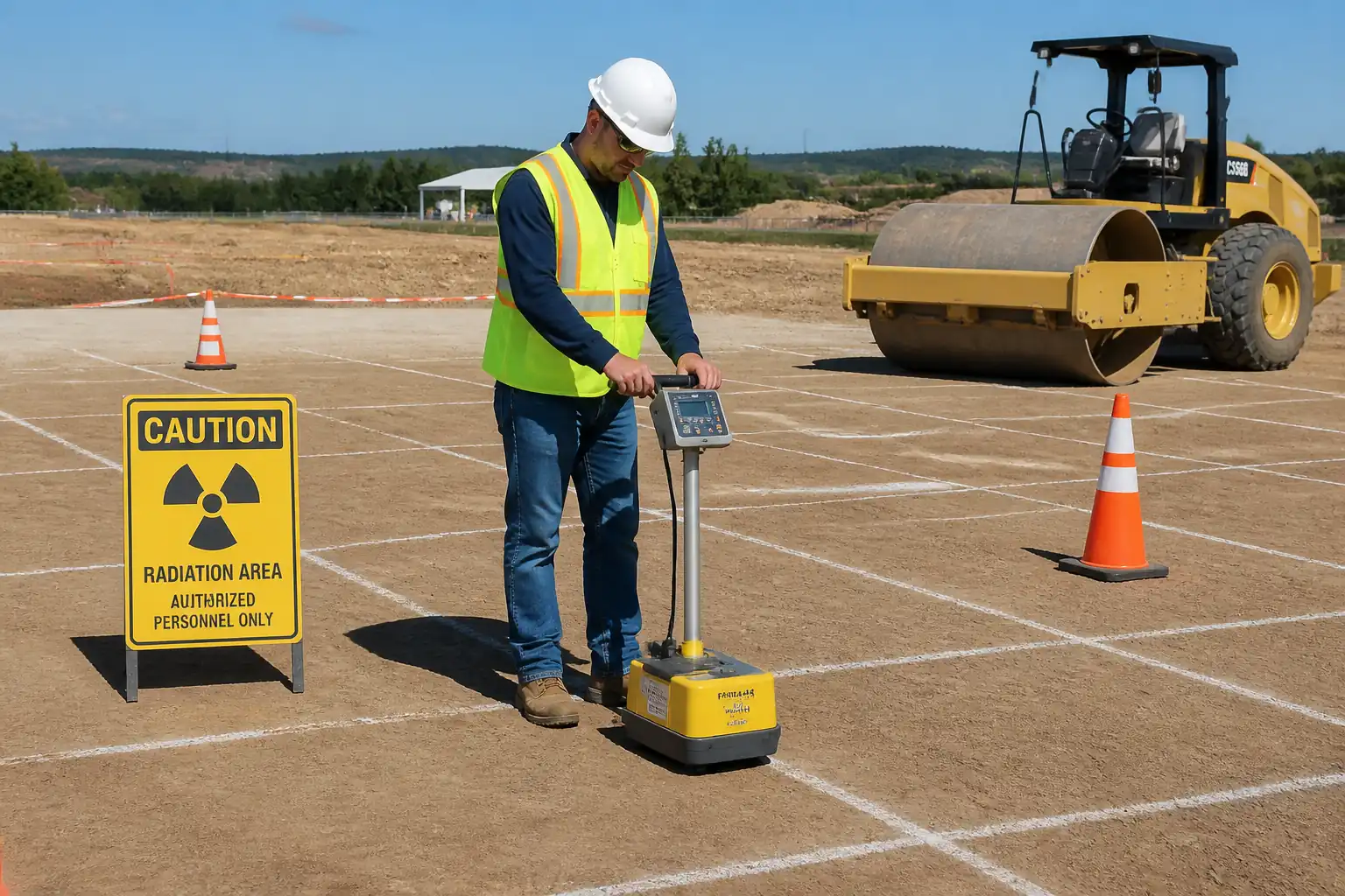
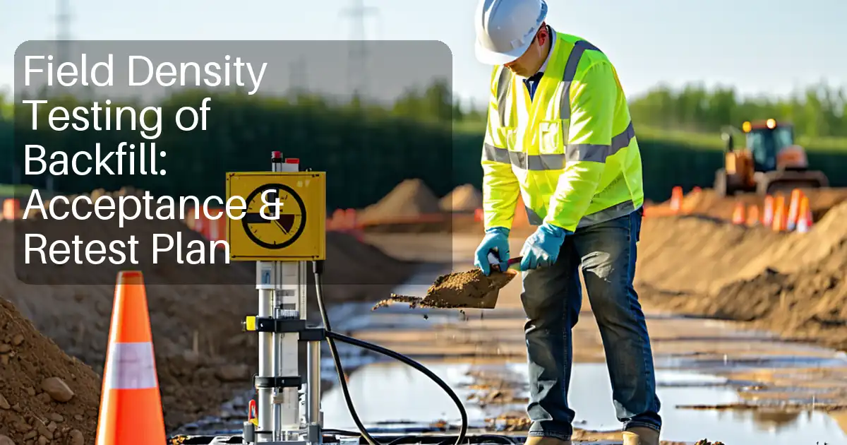
- Field density tests on sub-base: 1 test/250 m² per layer (min 2 per area) [Verify].
- Sieve analysis for bedding/jointing sand: 1 per source and 1 per 200 t or change of source [Verify].
- Paver compliance: Certificates per batch/delivery; random visual inspection each delivery.
- Straightedge checks: Every 25 m² or as directed.
Records
- ITP checklists, inspection forms, delivery dockets, test certificates, calibration records, as-built surveys, NCR/CCR logs, photographic records.
Nonconformance
- Identify, cordon area, record NCR; rectify by lifting pavers, adjusting bedding, re-laying, or replacing units; re-test/re-inspect prior to acceptance.
Attachments
Attached / Referenced Forms and Details
- ITP Checklists for each activity.
- Sub-base Field Density Test Report template.
- Bedding/Jointing Sand Sieve Analysis template.
- Edge Restraint Detail (typical section) – drawing reference.
- Trial Panel Approval form.
- Pre-start/Toolbox Talk attendance sheet.
- Plant Pre-use Inspection checklist (plate compactor, saws, levels).
- As-built survey template and straightedge check log.
This content is a read-only public reference. Download or customize to get an editable version.
ITP preview
The first inspection activities from the linked ITP for Method Statement: Installation of Interlocking Concrete Block Paving for Walkways and Driveways:
| Activity | Inspection / Test | Acceptance Criteria | Responsibility | Record |
|---|---|---|---|---|
| Materials – Pavers | Review EN 1338/ASTM C936 certificates; visual inspection of color, thickness, damage. | Compressive strength, absorption, abrasion per standard; appearance per approved sample; thickness as specified [Verify]. | QA/QC Engineer / Supplier | Certificates, delivery dockets, inspection log |
| Materials – Bedding/Jointing Sand | Sieve analysis; visual cleanliness; moisture checks. | Grading within limits; fines ≤3% (≤0.063 mm) [Verify]; free of organics/salts. | QA/QC Engineer | Test reports, supplier data |
| Subgrade Approval | Proof-roll; DCP/CBR if specified; level check. | No pumping/deflection; level within ±20 mm; falls achieved; soft spots rectified. | Site Engineer / Engineer Rep. | Inspection form, remediation log |
Showing 3 of 9 inspection activities. View full ITP →
Related Inspection and Test Plan
An Inspection and Test Plan (ITP) is available for Method Statement: Installation of Interlocking Concrete Block Paving for Walkways and Driveways. The ITP defines the inspection activities, acceptance criteria, hold and witness points, responsible parties, and records required to verify the work described in this method statement.
View the Method Statement: Installation of Interlocking Concrete Block Paving for Walkways and Driveways ITP →Frequently asked questions
Continue with related Quollnet resources connected to this method statement.