Method Statement: Field Density Testing of Compacted Fill Using Nuclear Density Gauge – Method Statement
AI-assisted method statement with matching ITP, PDF download, and Excel export.
More than a static template
Unlike a downloadable Word or PDF template, this method statement is an AI-assisted editable starting point connected directly to a matching Inspection and Test Plan. Every section is structured, project-adaptable, and ready to export.
- AI-assisted drafting — Customize every section with AI for your specific project scope.
- Linked ITP — A matching inspection and test plan is generated alongside the method statement.
- Multiple export formats — Download as a formatted PDF or editable Excel spreadsheet.
- Editable starting point, not a final document — Review, verify, and adjust all content against your project requirements before use.
Static template vs. Quollnet workflow
| Feature | Static template | Quollnet |
|---|---|---|
| Project-specific content | Manual fill-in required | AI-assisted customization |
| Linked ITP | Separate document, no link | Matching ITP included |
| Export formats | Usually PDF only | PDF and Excel |
| Structured sections | Free-form layout | 13 standardized sections |
| Saved to your account | Local file only | Cloud-saved, reusable |
| Content accuracy | You verify everything | AI-assisted, you still verify |
| Cost | Often free but time-intensive | Free to customize and download |
What you can customize
When you save this method statement to your account, every section becomes editable. The following 13 sections are included:
- Scope — Defines the activity and its boundaries.
- References — Standards, specifications, and drawings.
- Responsibilities — Roles and accountabilities.
- Resources — Labour, plant, and equipment summary.
- Materials — Materials and compliance requirements.
- Equipment — Tools and equipment details.
- Prerequisites — Hold points and pre-conditions.
- Method sequence — Step-by-step construction sequence.
- Safety controls — HSE risk controls and PPE.
- Environmental controls — Environmental mitigation measures.
- QA/QC — Quality inspection and test requirements.
- ITP — Inspection and Test Plan table (has its own page).
- Attachments — Referenced drawings and documentation.
Why this method statement is used
This method statement is used to define and communicate the approved procedure for carrying out method statement: field density testing of compacted fill using nuclear density gauge on site. It ensures the work is planned in advance, the correct resources and controls are in place, and all personnel understand responsibilities, sequence, quality requirements, and safety controls before work begins. It aligns site execution with the documented scope and acceptance expectations.
Who uses this method statement
This method statement is used by contractors, site supervisors, project engineers, QA/QC engineers, HSE officers, consultants, and client representatives. It serves as a shared reference for planning, execution, supervision, inspection, and approval of the activity on site.
When it is prepared and submitted
The method statement is prepared before the work activity starts and submitted as part of the pre-construction documentation package for review and approval.
Who reviews or approves it
The method statement is usually submitted to the client representative, consultant, resident engineer, or project management consultant for review and approval before the work commences.
Important approval note
This method statement is an AI-assisted editable starting point, not a pre-approved document. Before use on any project, all content must be reviewed and approved by the relevant parties (superintendent, principal contractor, or client representative) in accordance with your contract and project quality plan.
For example: if your specification requires a departure from a referenced standard, that departure must be documented and approved separately — this method statement will not capture that automatically. Always verify against your applicable drawings, specifications, and regulatory requirements.
Method statement content
Scope
Purpose
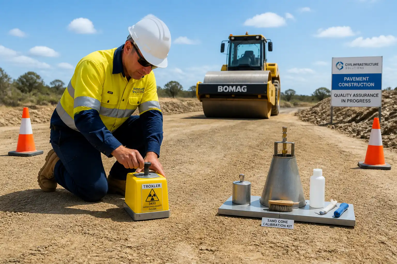
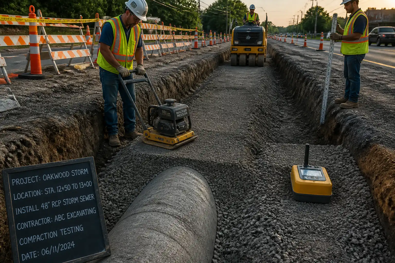
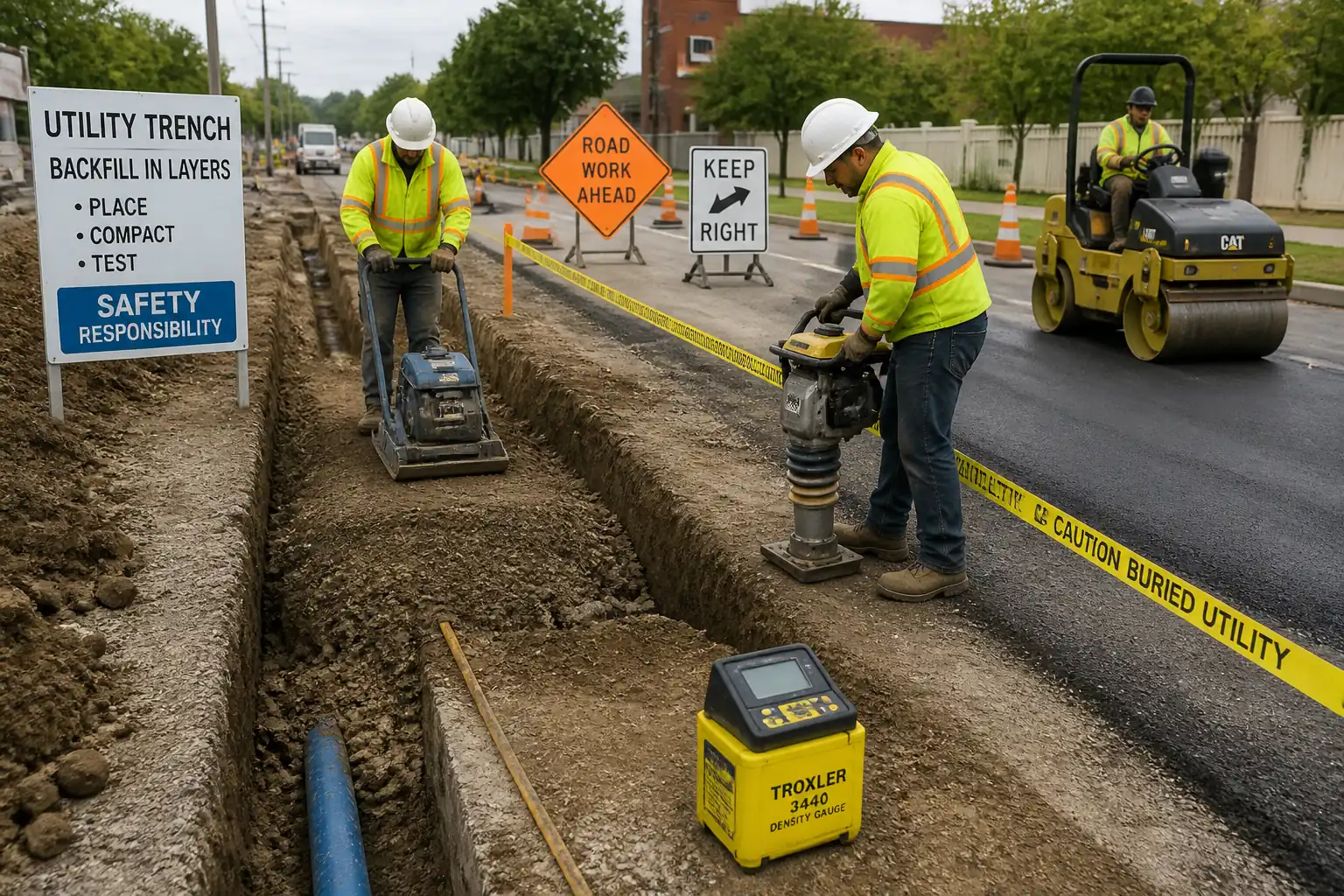
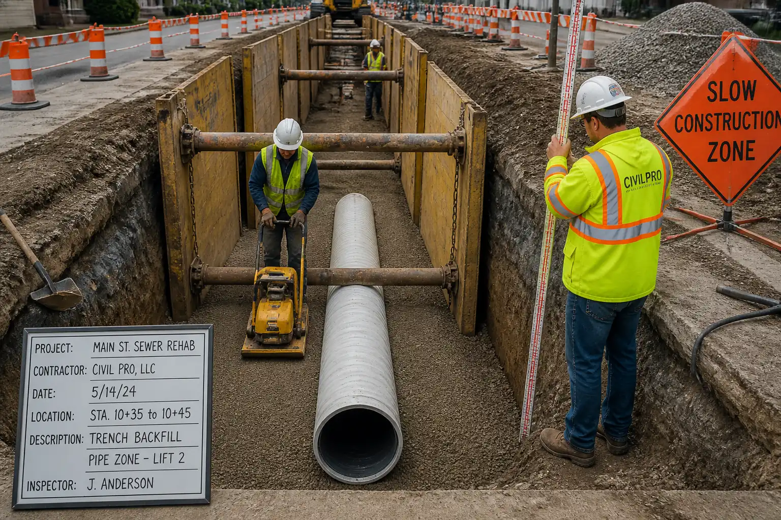
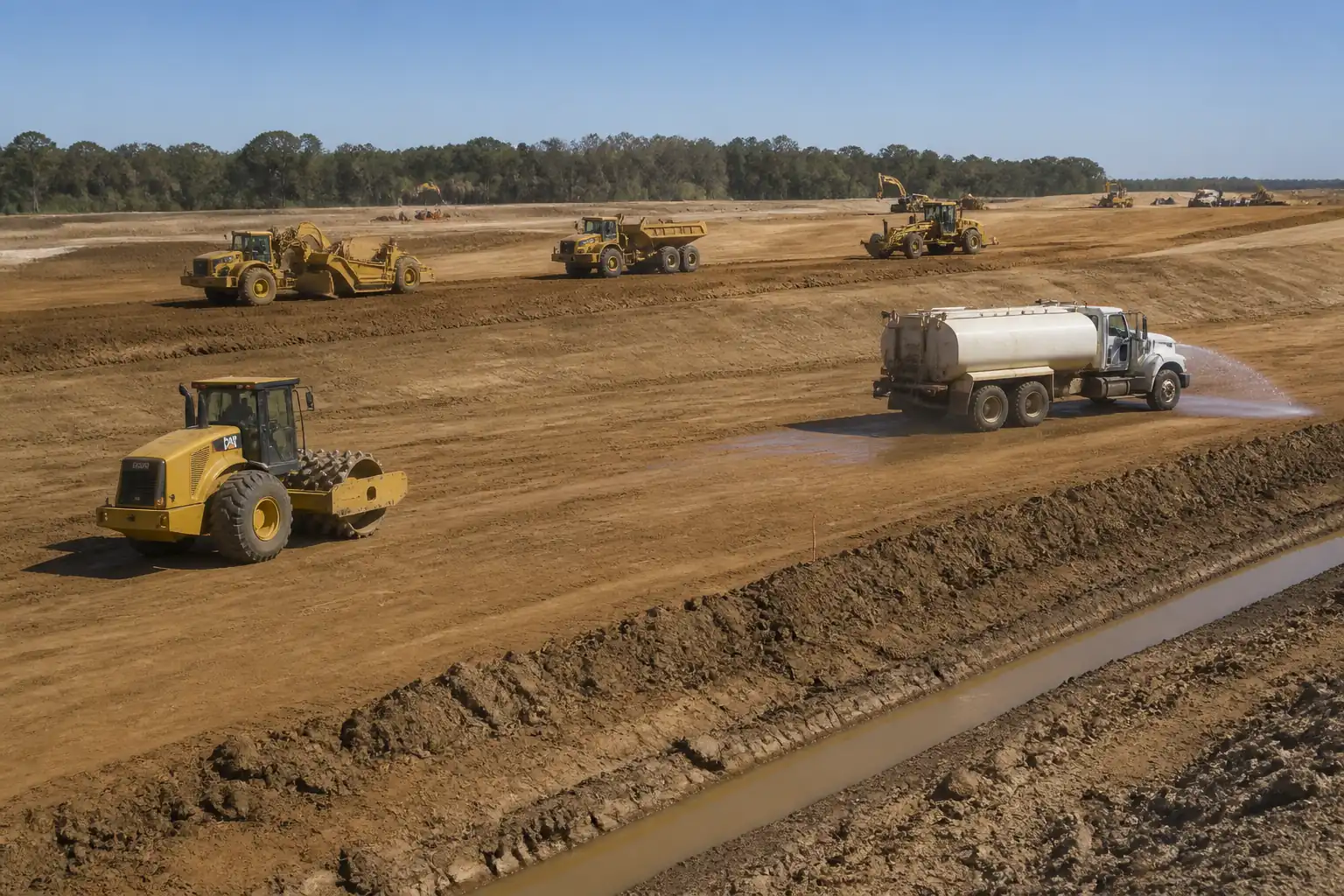
This method defines the procedure for field density and moisture testing of compacted fill layers (earthworks, subgrade, capping, granular sub-base, trench backfill) using a nuclear density gauge, including:
- Establishing test locations on a defined grid/randomized pattern per lot.
- Daily standardization and routine checks of the gauge.
- Execution of density/moisture measurements (direct transmission/backscatter as appropriate).
- Correlation and verification using the sand replacement (sand cone) method.
- Documentation, assessment against acceptance criteria, and hold-point release to proceed with the next lift.
Scope of Application
- Materials: Cohesive and granular soils, engineered fills, and unbound aggregates within the gauge measurement capability (typical maximum particle size ≤ 63 mm for reliable readings) [Verify per project specifications].
- Lift thickness: Typically 150–300 mm; gauge measurement depth selected to match lift thickness and method (direct transmission preferred for thicker lifts). [Verify per project specifications].
Exclusions/Limitations
- Materials with high organic content, very coarse fills, or highly open-graded aggregates where nuclear gauge correlation is unreliable shall be verified by sand replacement or alternative approved method.
- Saturated conditions or standing water at the surface invalidate readings; testing shall be postponed or sand cone used once suitable.
- Testing of chemically stabilized layers may require specific corrections and alternative references (e.g., time-dependent moisture loss). [Verify per project specifications].
References
| Document Type | Reference / Number | Revision | Notes |
|---|---|---|---|
| ASTM D6938 | Primary field test standard for nuclear density gauge use. | ||
| ASTM D1556 | Correlation/verification method (sand replacement). | ||
| ASTM D698 | Determines MDD/OMC for acceptance vs. percentage compaction. | ||
| ASTM D1557 | Determines MDD/OMC where higher compaction is specified. | ||
| BS 1377-9 | UK reference equivalent for sand replacement. | ||
| ASTM C1077 / ISO/IEC 17025 | Quality management/competence of testing entities [Verify applicable]. | ||
| IAEA SSR-6 | For transport/handling of nuclear gauges [Verify per local regulations]. | ||
| Gauge OEM Manual (e.g., Troxler/InstroTek) | Operating procedures, standardization, corrections, leak tests. | ||
| Acceptance criteria, test frequencies, hold points [Verify per project specifications]. |
Responsibilities
| Role | Responsibility | Name / Party |
|---|---|---|
| Contractor Project Manager | Overall implementation of this method, provision of resources, coordination with Engineer, ensuring compliance with HSE and radiation regulations. | Contractor |
| QA/QC Engineer | Execution of field tests, identification of test lots/locations, documentation, immediate reporting of nonconformities, coordination of rework and retests. | Contractor |
| Nuclear Gauge Operator / Technician | Daily standardization, operation and custody of gauge, radiation safety compliance, leak test records, dosimetry, transport/secure storage of gauge. | Contractor |
| Radiation Safety Officer (RSO) | Radiation Safety Plan, licensing/permitting, supervision of radiation controls, audits, training, incident response. | Contractor |
| Surveyor | Set-out of test grid/locations, as-built coordinates, ensuring lot boundaries are correctly defined. | Contractor |
| Site Supervisor / Foreman | Interface with compaction crew/plant, ensures safe work area, assists with access and traffic control. | Contractor |
| HSE Officer | Monitors HSE compliance, radiation signage/cordons, permits, and PPE checks. | Contractor |
| Engineer/Consultant Representative | Witnesses inspections/tests per ITP, reviews results, approves or rejects lots, releases hold point for next lift. | Engineer |
Resources
| Resource Type | Description | Quantity | Remarks |
|---|---|---|---|
| Personnel | 1–2 per shift [Verify] | ||
| Personnel | 1 | ||
| Personnel | As required | ||
| Personnel | 1 | ||
| Personnel | 1–2 |
Materials
| Material | Specification / Grade | Quantity | Remarks |
|---|---|---|---|
| Standard Calibration Sand | ASTM D1556-compliant | As needed for checks | |
| Moisture tins, density cans, sample bags | ASTM-compliant | As needed |
Equipment
| Equipment | Capacity / Type | Quantity | Inspection Required |
|---|---|---|---|
| Nuclear Density Gauge | ASTM D6938-compliant | 1–2 | Daily standardization; annual calibration [Verify]. |
| Gauge Accessories | 1 set | Visual before use | |
| Sand Replacement Apparatus | ASTM D1556-compliant | 1 set | Calibration check before use |
| Laboratory Equipment | ASTM-compliant | As required | Calibration per QA plan |
| Survey & Safety Accessories | As required | Pre-use checks; permits/licenses valid [Verify]. |
Prerequisites
- Approved ITP and Method Statement for field density testing.
- Current laboratory compaction curves (MDD/OMC) for each material type and source per ASTM D698 or ASTM D1557, as specified.
- Valid calibration, standardization, and leak test certificates for the nuclear gauge; operator licenses and radiation training records current. [Verify per local regulations]
- Radiation Safety Plan approved, controlled storage, transport authorization, and dosimetry arrangements in place.
- Defined test lots and acceptance criteria approved by the Engineer.
- Survey set-out of lot boundaries and proposed test grids, including randomization method.
- Traffic management plan for access around compaction plant; exclusion zones defined.
- Weather check: no standing water, heavy rain, or extreme temperature that would invalidate readings.
- Toolbox talk covering radiation hazards, site access, and testing sequence.
- Hold/witness points communicated as per ITP.
Method Sequence
| Step | Activity | Description | Responsibility | Inspection / Hold Point |
|---|---|---|---|---|
| 1 | Confirm test lot and acceptance criteria | Identify material type, lift thickness, area/volume, and required degree of compaction (e.g., ≥95% of MDD for standard Proctor, or ≥98% for modified) and moisture tolerance (e.g., OMC −2% to +1%) [Verify per project specifications]. Define lot size and minimum number of tests. | QA/QC Engineer | ITP Witness |
| 2 | Lay out test grid and randomize locations | Set out a uniform grid (typical 10–20 m spacing for large areas; trenches: 1 test per 50 m per lift) with random offset within each grid cell. Mark positions with paint/flag and record coordinates. [Verify frequency per project specifications] | Surveyor / QA/QC | ITP Witness |
| 3 | Daily gauge standardization | Place gauge on manufacturer’s reference block on stable surface; perform standard count per ASTM D6938 and OEM manual. Verify counts within allowable drift (typical ±1% from reference) [Verify per OEM]. Record results before any testing. | Gauge Operator / RSO oversight | Hold |
| 4 | Surface preparation at test location | Scrape and level the test surface; remove loose material, stones protruding, and organic matter. Ensure intimate contact between gauge base and surface. For direct transmission, drill an access hole with drive rod to the selected depth (typically 100–150 mm matching lift thickness). | Gauge Operator | Visual |
| 5 | Measurement – select mode and depth | - If lift thickness ≥ 100 mm and material permits, use direct transmission at a depth approximating 2/3 to full lift thickness (typ. 100–150 mm). - If thin lift (<100 mm) or obstructions exist, use backscatter mode with thin-lift correction per OEM. - Seat the gauge, align, insert/withdraw source rod smoothly to selected depth/position. | Gauge Operator | ITP Witness (as required) |
| 6 | Counting procedure | Take minimum 1-minute count. Where specified, take multiple readings (e.g., 2–4 rotations around center at 90°) and average. Record wet density, dry density, and moisture content from gauge display. | Gauge Operator | Spot checks |
| 7 | Independent moisture verification (as required) | Obtain a representative sample within 300 mm of test point; determine moisture by oven-drying (105–110°C) or speedy moisture where permitted. Compare with gauge moisture; apply correction if project procedure allows. | QA/QC Lab Technician | ITP Witness (as required) |
| 8 | Sand replacement correlation/verification | At start of works, after calibration, and at defined frequency (e.g., first 5 tests for each material/lot and weekly thereafter, or when material/source changes), perform paired tests: nuclear reading then sand cone at the same location. Compute correction/bias per ASTM D6938/OEM. Investigate if differences exceed typical ±3% dry density (or ±50 kg/m³) [Verify]. | QA/QC Engineer / Technician | Hold/Witness |
| 9 | Assess compliance and manage nonconformities | Calculate % compaction = (Field dry density / MDD) × 100. Check moisture vs tolerance. If fail: instruct rework (additional compaction or moisture conditioning) and retest. Define retest pattern (e.g., test failed point and two adjacent points). | QA/QC Engineer / Site Supervisor | ITP Witness (as required) |
| 10 | Hold-point release for next lift | Submit lot test summary with locations, results, correlation evidence, and certificates. Upon Engineer approval, release hold point and authorize placement/compaction of the next lift. | Contractor PM / QA/QC; Engineer | Hold |
Health, Safety, and Environment (HSE) – Safety Controls
Task-specific hazards and controls
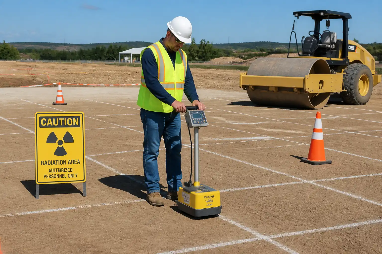
- Hazard: Ionizing radiation exposure from nuclear gauge.
- Likely consequence: Deterministic/stochastic health effects; regulatory breach.
- Engineering/procedural control: Use only trained, authorized operators; keep source locked when not measuring; establish 2–3 m exclusion zone around gauge; do not point source at personnel; minimize time with source extended; use transport case and vehicle mounts; secure storage in approved facility; leak tests and standardization as per OEM/regulator. [Verify per project HSE plan and local regulations]
- Required PPE: Dosimeter (personal), gloves when handling gauge, safety boots, high-vis, hard hat, eye protection.
- Collective preventive measure: Barriers and radiation signage; scheduling to avoid crowding; toolbox talks.
-
Inspection/permit/supervision: Radiation Safety Plan, operator authorization, RSO oversight, licenses/permits, daily pre-use checks, periodic audits.
-
Hazard: Plant–people interface (rollers, dumpers, graders near test area).
- Likely consequence: Struck-by/crush injury.
- Engineering/procedural control: Traffic management plan; radio contact with plant; spotter/banksman; isolate test area with cones/flagging during measurements; no reversing near gauge zone.
- PPE: High-vis, hard hat, safety boots.
- Collective measure: Physical barriers, exclusion zone.
-
Inspection/permit/supervision: Daily TBT; supervisor to coordinate with plant operators; compliance checks.
-
Hazard: Manual handling of gauge (approx. 7–9 kg) and accessories.
- Likely consequence: Strains/soft-tissue injury.
- Control: Use correct lifting technique; carry in both hands; use trolley for long distances; team lift over rough ground.
- PPE: Gloves, boots.
- Collective measure: Use mechanical aids.
-
Inspection/permit/supervision: Manual handling training; supervisor monitoring.
-
Hazard: Slips, trips, uneven ground, open test holes.
- Consequence: Falls, sprains.
- Control: Level test pads; fill probe holes after testing; maintain housekeeping; adequate lighting if low visibility.
- PPE: Boots with ankle support.
- Collective measure: Barricade test area.
-
Inspection/permit/supervision: Site inspections by HSE; close-out of holes before demobilizing.
-
Hazard: Heat/cold stress and dehydration during outdoor testing.
- Consequence: Heat exhaustion, hypothermia.
- Control: Work/rest regime; hydration stations; shade; adjust schedule.
- PPE: Weather-appropriate clothing, sun protection.
- Collective measure: Shelter and cool-down areas.
-
Inspection/permit/supervision: HSE monitoring; stop-work criteria for extreme conditions.
-
Hazard: Noise and vibration from nearby compaction equipment.
- Consequence: Hearing damage, distraction.
- Control: Maintain distance; hearing protection as required; coordinate testing when equipment is idle.
- PPE: Ear protection where applicable.
- Collective measure: Quiet zone during counting.
-
Inspection/permit/supervision: HSE spot checks.
-
Hazard: Vehicle transport of gauge on public roads.
- Consequence: Regulatory non-compliance, collision risk.
- Control: Approved transport container and placarding; secure gauge per IAEA/Regulator; driver training; route planning.
- PPE: As per driving policy.
- Collective measure: Vehicle inspection program.
- Inspection/permit/supervision: Transport license/documents; RSO checks.
Environmental Controls
- Radiation source security and stewardship
- Impact: Unauthorized access, loss, or theft of radioactive material.
-
Control: Secure storage with access control; chain-of-custody log; immediate reporting of loss/theft; inventory checks each shift. [Verify per local regulations]
-
Dust generation from surface preparation
- Impact: Air quality, nuisance.
-
Control: Light misting if needed; avoid testing during high winds; no excessive scraping beyond area required.
-
Noise from nearby equipment
- Impact: Community disturbance, fauna.
-
Control: Limit testing to approved hours; coordinate with plant to minimize idling.
-
Waste management
- Impact: Litter, contamination.
-
Control: Collect and dispose of used sample bags/tins; reclaim calibration sand; label and store moisture tins for reuse; manage oven waste heat safely.
-
Spill prevention (oils/fuels from support vehicle)
- Impact: Soil/water contamination.
-
Control: No refueling in test area; spill kits available; report and remediate spills immediately.
-
Energy use and emissions
- Impact: Carbon footprint.
- Control: Combine testing trips; plan efficient routes; turn off engines when stationary.
Quality Assurance / Quality Control
Acceptance criteria [Verify per project specifications]
- Degree of compaction: Typically ≥95% MDD (Standard Proctor) or ≥98% MDD (Modified Proctor) as specified.
- Moisture content: Typically within OMC −2% to +1% for cohesive soils; OMC −2% to +2% for granular fills.
- Gauge standardization: Daily counts within OEM/ASTM limits (typ. ±1%).
- Correlation: Nuclear vs sand cone differences within ±3% dry density or project-defined tolerance; bias/correction documented.
Testing frequency (typical benchmarks)
- Areas: Minimum 1 test per 500 m² per lift, with not less than 3 tests per lot.
- Linear works: Minimum 1 test per 50 m per lift per lane/trench.
- Volume-based: 1 test per 250 m³ per lift.
Use the stricter of project specification or these benchmarks.
Data handling and traceability
- Each test reported with: Lot ID, material, lift thickness, location coordinates, mode/depth, wet/dry density, moisture, % compaction, MDD/OMC reference, gauge serial, operator, time/date, weather, corrections applied.
- Maintain unique sample/test IDs linked to grid and drawings.
- Record all standardizations, leak tests, calibrations, and correlation computations.
Nonconformance and retesting
- If a result fails: Implement corrective actions (re-compact, adjust moisture). Retest failed point and at least two adjacent points. Record actions and outcomes. Persistent failures trigger NCR and root-cause analysis.
Rounding and calculations
- Report densities to nearest 1 kg/m³; moisture to 0.1%; compaction to 0.1%.
- Use current approved MDD/OMC for the exact material lot/source.
Document retention
- Retain all field and lab records, licenses, and approvals for the duration of the project plus the contractually required period.
Attachments
- Sample Field Density Test Report (ASTM D6938) – template.
- Sample Sand Replacement Test Report (ASTM D1556) – template.
- Daily Standardization Log – template.
- Radiation Safety Plan summary and licenses – copies.
- Current MDD/OMC laboratory compaction curves for all materials – copies.
- Lot Register and Grid Plan – sample.
- Manufacturer’s gauge operation and safety instructions – extract.
This content is a read-only public reference. Download or customize to get an editable version.
ITP preview
The first inspection activities from the linked ITP for Method Statement: Field Density Testing of Compacted Fill Using Nuclear Density Gauge:
| Activity | Inspection / Test | Acceptance Criteria | Responsibility | Record |
|---|---|---|---|---|
| Approval of method statement and ITP | Document review and approval | Approved documents issued for use | Contractor PM / Engineer | Approved MS & ITP with signatures |
| Gauge calibration and certification | Review calibration and leak test certificates | Valid within required intervals; compliant with regulator/OEM | RSO / QA/QC Engineer | Calibration & Leak Test Certificates |
| Daily standardization (Hold) | Standard count on reference block | Within OEM/ASTM tolerance; else withdraw from service | Gauge Operator / RSO | Daily Standardization Log |
Showing 3 of 8 inspection activities. View full ITP →
Related Inspection and Test Plan
An Inspection and Test Plan (ITP) is available for Method Statement: Field Density Testing of Compacted Fill Using Nuclear Density Gauge. The ITP defines the inspection activities, acceptance criteria, hold and witness points, responsible parties, and records required to verify the work described in this method statement.
View the Method Statement: Field Density Testing of Compacted Fill Using Nuclear Density Gauge ITP →Frequently asked questions
Continue with related Quollnet resources connected to this method statement.