Method Statement: In‑Situ Density and Moisture Content Testing of Earthworks Layers (Sand Replacement and Nuclear Methods) – Method Statement
AI-assisted method statement with matching ITP, PDF download, and Excel export.
More than a static template
Unlike a downloadable Word or PDF template, this method statement is an AI-assisted editable starting point connected directly to a matching Inspection and Test Plan. Every section is structured, project-adaptable, and ready to export.
- AI-assisted drafting — Customize every section with AI for your specific project scope.
- Linked ITP — A matching inspection and test plan is generated alongside the method statement.
- Multiple export formats — Download as a formatted PDF or editable Excel spreadsheet.
- Editable starting point, not a final document — Review, verify, and adjust all content against your project requirements before use.
Static template vs. Quollnet workflow
| Feature | Static template | Quollnet |
|---|---|---|
| Project-specific content | Manual fill-in required | AI-assisted customization |
| Linked ITP | Separate document, no link | Matching ITP included |
| Export formats | Usually PDF only | PDF and Excel |
| Structured sections | Free-form layout | 13 standardized sections |
| Saved to your account | Local file only | Cloud-saved, reusable |
| Content accuracy | You verify everything | AI-assisted, you still verify |
| Cost | Often free but time-intensive | Free to customize and download |
What you can customize
When you save this method statement to your account, every section becomes editable. The following 13 sections are included:
- Scope — Defines the activity and its boundaries.
- References — Standards, specifications, and drawings.
- Responsibilities — Roles and accountabilities.
- Resources — Labour, plant, and equipment summary.
- Materials — Materials and compliance requirements.
- Equipment — Tools and equipment details.
- Prerequisites — Hold points and pre-conditions.
- Method sequence — Step-by-step construction sequence.
- Safety controls — HSE risk controls and PPE.
- Environmental controls — Environmental mitigation measures.
- QA/QC — Quality inspection and test requirements.
- ITP — Inspection and Test Plan table (has its own page).
- Attachments — Referenced drawings and documentation.
Why this method statement is used
This method statement is used to define and communicate the approved procedure for carrying out method statement: in‑situ density and moisture content testing of earthworks layers (sand replacement and nuclear methods) on site. It ensures the work is planned in advance, the correct resources and controls are in place, and all personnel understand responsibilities, sequence, quality requirements, and safety controls before work begins. It aligns site execution with the documented scope and acceptance expectations.
Who uses this method statement
This method statement is used by contractors, site supervisors, project engineers, QA/QC engineers, HSE officers, consultants, and client representatives. It serves as a shared reference for planning, execution, supervision, inspection, and approval of the activity on site.
When it is prepared and submitted
The method statement is prepared before the work activity starts and submitted as part of the pre-construction documentation package for review and approval.
Who reviews or approves it
The method statement is usually submitted to the client representative, consultant, resident engineer, or project management consultant for review and approval before the work commences.
Important approval note
This method statement is an AI-assisted editable starting point, not a pre-approved document. Before use on any project, all content must be reviewed and approved by the relevant parties (superintendent, principal contractor, or client representative) in accordance with your contract and project quality plan.
For example: if your specification requires a departure from a referenced standard, that departure must be documented and approved separately — this method statement will not capture that automatically. Always verify against your applicable drawings, specifications, and regulatory requirements.
Method statement content
Scope
Purpose
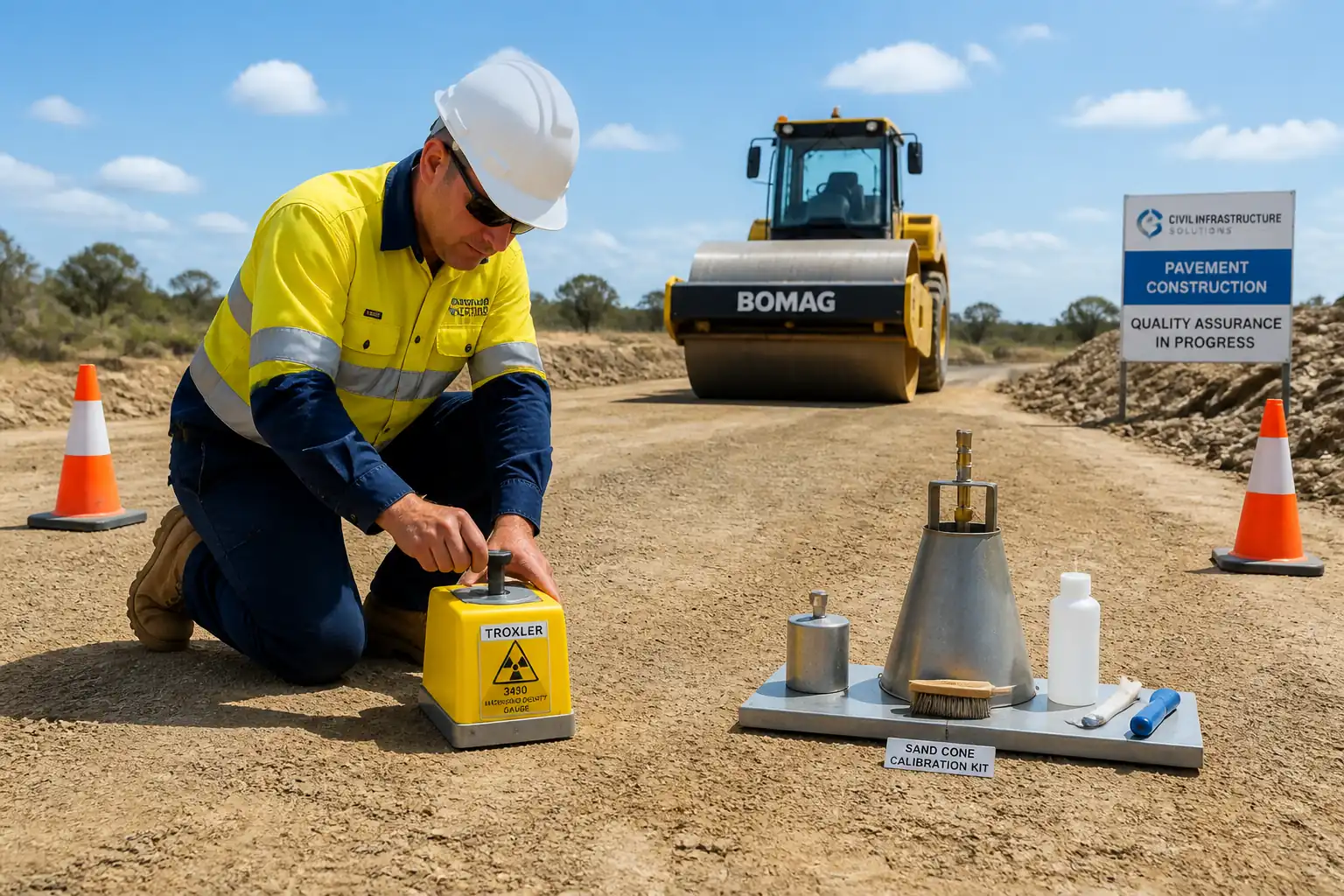
This method statement defines the procedures, quality controls, acceptance criteria, HSE measures, and documentation for in-situ density and moisture content testing of compacted earthworks layers using:
- Sand replacement (sand cone) method
- Nuclear density gauge (backscatter and direct transmission)
Scope of Work
- Earthworks layers: general fill, engineered fill, embankments, formation/subgrade, capping, subbase/base of unbound materials [Verify per project scope]
- Verification against laboratory Proctor compaction curves (Standard or Modified)
- Test frequency per project specifications; typical benchmark frequencies are provided where unspecified [Verify per project specifications]
- Reporting to QA/QC and support to acceptance/rework decisions
Exclusions
- Asphalt and cement-treated materials (covered under separate methods)
- Laboratory Proctor determination (covered under laboratory SOP)
Definitions
- MDD: Maximum Dry Density from laboratory Proctor
- OMC: Optimum Moisture Content from laboratory Proctor
- Degree of Compaction (%DoC): (Field dry density / MDD) × 100%
References
| Document Type | Reference / Number | Revision | Notes |
|---|---|---|---|
| Standard | ASTM D1556/D1556M | ||
| Standard | ASTM D6938 | ||
| Standard | ASTM D698; ASTM D1557 | ||
| Standard | ASTM D2216 | ||
| Standard | BS 1377-2 | Use where specified or for Speedy moisture tester correlation [Verify per project specifications]. | |
| Standard | EN 13286-2 | Use if European standards are specified [Verify per project specifications]. | |
| Standard | ISO 9001; ISO/IEC 17025 | Applicable to contractor QA system and accredited testing laboratory. | |
| Manual | Gauge OEM Manual | Follow OEM tolerances where more stringent than standards. |
Responsibilities
| Role | Responsibility | Name / Party |
|---|---|---|
| Project Manager | Ensure method and ITP approved and implemented | Contractor |
| Site Engineer | Issue RFIs/IRs, mark test lots, control sequence | Contractor |
| QA/QC Engineer | Review Proctor, verify frequency, check calculations, issue NCRs | Contractor |
| Technician | Conduct tests per standard; record raw data; maintain logs | Contractor/Lab |
| RPO/RPS | Permits, training, leak tests, dosimetry, incident response | Contractor or Licensed Supplier |
| Engineer | Review results; approve hold points; instruct rework | Engineer/Consultant |
Resources
| Resource Type | Description | Quantity | Remarks |
|---|---|---|---|
| Manpower | Trained and certified for ASTM D1556/D6938 | 1–2 | |
| Manpower | Set out and record test locations | As required | |
| Specialist | Radiation safety oversight | Shared resource | |
| Manpower | Traffic and plant interface control | As needed |
Materials
| Material | Specification / Grade | Quantity | Remarks |
|---|---|---|---|
| Ottawa or local equivalent | As required | ||
| Sufficient for daily tests | |||
| As required |
Equipment
| Equipment | Capacity / Type | Quantity | Inspection Required |
|---|---|---|---|
| 1 set/crew | |||
| 1 | |||
| 1 field + 1 lab | |||
| 1 | |||
| 1 per crew | Yes | ||
| As required | |||
| 1 |
Prerequisites
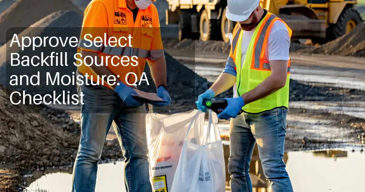
- Approved earthworks method statement and this testing method with ITP.
- Current laboratory Proctor results for each material source and compaction energy (ASTM D698 or D1557; EN 13286-2). Identify MDD (kg/m³) and OMC (%).
- Defined lots and sublots per specification. Typical lot definition: each 500 m length of layer or 2,500 m² of uniform layer thickness [Verify per project specifications].
- Confirm minimum layer thickness appropriate for test method: nuclear backscatter typically ≥75–100 mm; sand-cone hole depth representative of the compacted lift thickness.
- Equipment calibration certificates: balances, ovens, nuclear gauge (annual), leak test (semi-annual/annual per authority), daily standardization log ready.
- RFI/Inspection Request submitted and test schedule agreed with Engineer (with proposed random test locations).
- Site prepared: final compaction completed; surface trimmed; free of standing water; safe access; exclusion zones established; plant movement controlled.
- Radiation permits/authorizations, operator licenses, dosimeters, transport/secure storage arrangements for nuclear gauge [Verify per project HSE plan and local regulations].
- Toolbox talk conducted: method, hazards (including radiation), emergency procedures, communication, and exclusion zones.
- Weather check: avoid heavy rain or high winds causing sand loss or unstable readings; record ambient conditions.
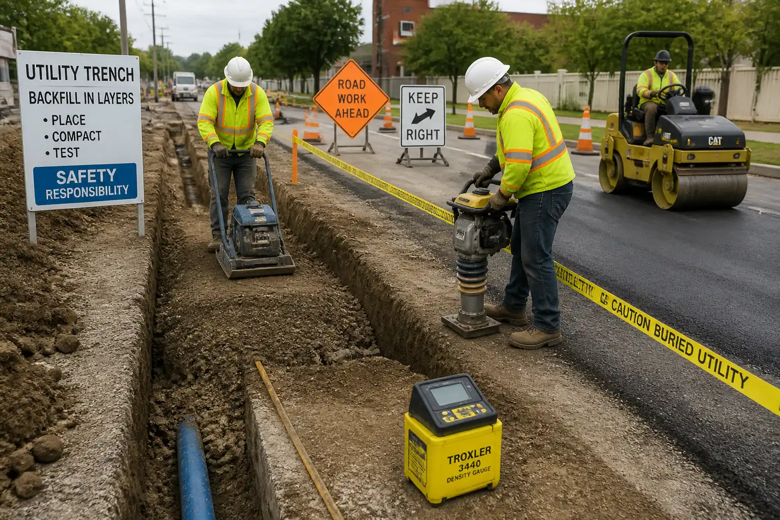
Method Sequence
| Step | Activity | Description | Responsibility | Inspection / Hold Point |
|---|---|---|---|---|
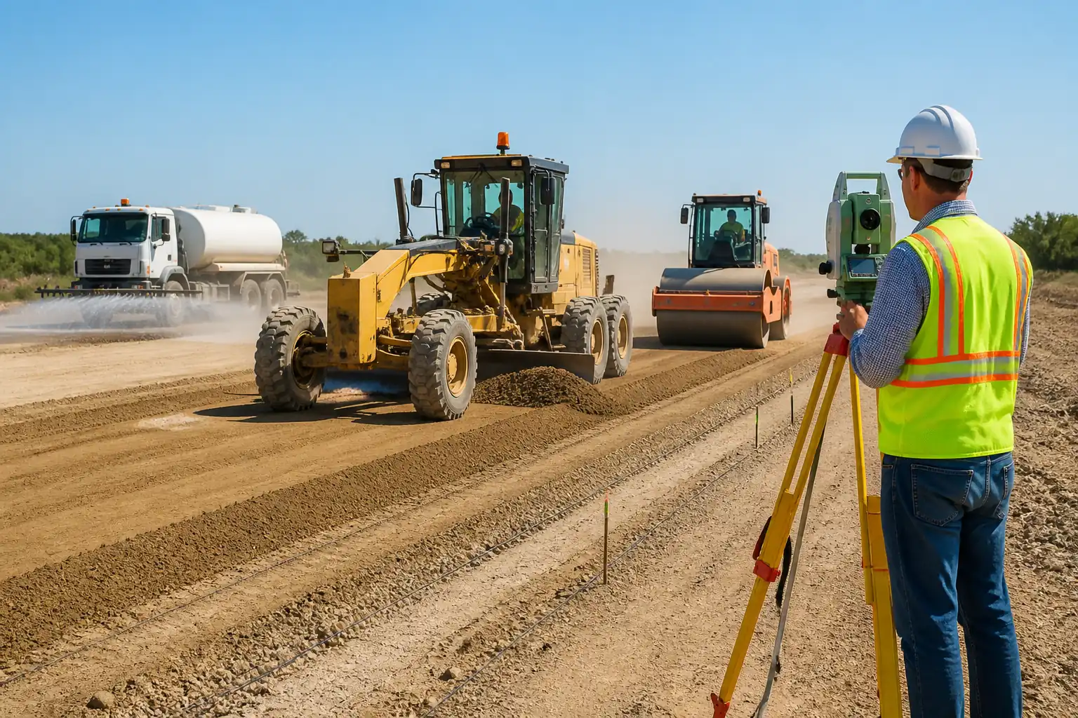
| 1 | Confirm test lot and select random locations | Define lot/sublot. Use stratified random selection or random-number grid. Minimum separation from edges typically ≥3× layer thickness (or ≥0.5 m). Mark with paint/flags and record coordinates. | Site Engineer / QA/QC | Hold Point: Engineer may witness location selection |
| 2 | Verify Proctor reference and target | Identify applicable Proctor (Std/Mod) and material ID for each lot. Extract MDD and OMC from approved lab report. Set acceptance criteria per spec. | QA/QC Engineer | Review |
| 3 | Daily instrument checks | Balances zero check; oven temperature verification; nuclear gauge standardization on reference block (record counts). | Technician | Witness (QA/QC) |
| 4 | Sand-Cone Method: prepare site | Place baseplate flush on compacted surface; brush fines to ensure tight seal. Avoid vibration during test. | Technician | |
| 5 | Sand-Cone Method: excavate test hole | Cut hole through center of baseplate using hand tools. Diameter typically 150–200 mm; depth representative of layer (usually 100–200 mm). Collect entire excavated soil for moisture and wet mass. | Technician | |
| 6 | Sand-Cone Method: determine hole volume | Weigh sand cone + jar before and after filling hole. Use pre-determined bulk density of sand (from calibrating cylinder). Account for apparatus and baseplate volumes per standard. | Technician | |
| 7 | Sand-Cone Method: moisture content | Determine moisture content of the recovered sample by oven (105 ± 5°C) to constant mass; or use Speedy tester only if permitted and correlated. | Technician (Lab) | |
| 8 | Nuclear Gauge: site check and mode selection | Ensure exclusion from large metallic objects (>300 mm), standing water, or voids. Select backscatter for thin lifts (≥75–100 mm). For thicker lifts, use direct transmission with probe driven to target depth. | Technician | |
| 9 | Nuclear Gauge: take counts | Perform a minimum 60-second count. Take two replicate readings at the same spot (rotate gauge 90° if allowed). For direct transmission, predrill with guide sleeve and drive probe carefully. | Technician | |
| 10 | Calculate dry density and %DoC | Sand-cone: γd = (Wet mass - Water mass)/Hole volume. Nuclear: use gauge output. Compute %DoC = γd(field)/MDD × 100. Determine moisture deviation from OMC. | Technician / QA | Review by QA/QC |
| 11 | Acceptance decision and rework (if needed) | Compare to criteria. Typical: General fill ≥95% MDD (Std Proctor); Subgrade/Capping ≥95–98%; Subbase/Base ≥98% (Mod Proctor). Moisture typically within −2% to +1% of OMC [Verify per project]. | QA/QC Engineer / Engineer | |
| 12 | Test frequency and additional testing | Apply specified frequency. Typical benchmarks: General fill 1/250 m³ or 1/500 m² per layer; Subgrade 1/250 m²; Capping/Subbase 1/250–500 m² per layer. Increase frequency after failures (e.g., +50%) until stable. | QA/QC Engineer | |
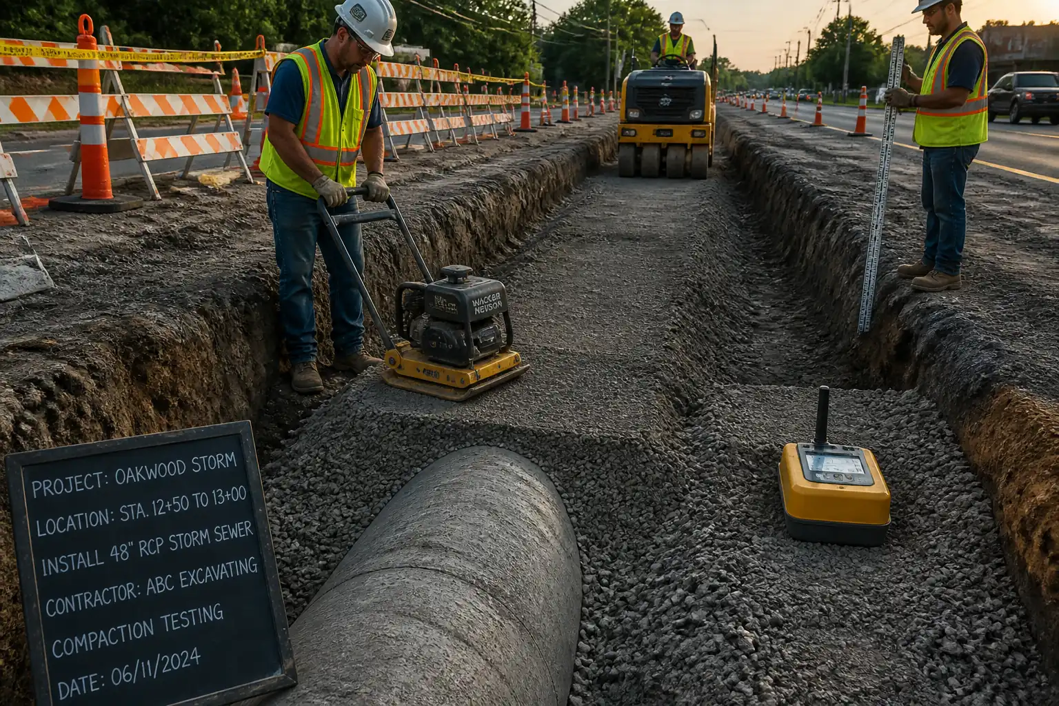
| 13 | Reporting and records | Issue daily field density summary with locations, method, raw/processed data, %DoC, moisture, equipment IDs, calibrations, weather, and acceptance status. Submit to Engineer within 24 hours or as stipulated. | QA/QC Engineer | |
| 14 | Housekeeping and demobilization | Backfill sand-cone holes; remove surplus sand; restore surface; secure nuclear gauge in approved storage/vehicle lockbox. | Technician / Supervisor |
Health, Safety, and Environment (HSE) – Safety Controls
Task-specific Hazards and Controls
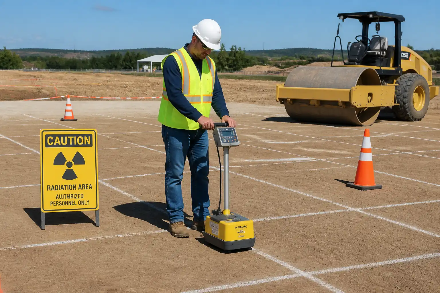
1) Hazard: Ionizing radiation from nuclear density gauge
- Consequence: Radiation exposure, contamination, regulatory breach
- Engineering/Procedural Control: Use only by trained, authorized operators; maintain exclusion zone radius ≥3 m; do not point source at personnel; daily standardization; transport and storage in locked, labeled container; source rod only extended when seated; time–distance–shielding principles
- Required PPE: Dosimeter/TLD, gloves for handling, hi-vis, helmet, safety boots
- Collective Preventive Measure: Physical barriers/cones, signage “Radiation – Controlled Area,” job briefing to all nearby crews
- Inspection/Permit/Supervision: Radiation permit/authorization; RPO oversight; leak test and calibration certificates; regulatory license available on site [Verify per project HSE plan and local regulations]
2) Hazard: Traffic and heavy plant interaction near test locations
- Consequence: Collision/struck-by injuries
- Engineering/Procedural Control: Traffic management plan; establish exclusion zone around test; banksman control; schedule tests outside peak plant movements
- PPE: Hi-vis, helmet, safety boots
- Collective Preventive Measure: Barriers and spotters; diversion signage
- Inspection/Permit/Supervision: Daily permit-to-work/TA for work in live areas; supervisor presence
3) Hazard: Hand tools and probe driving (pinch/cut/impact)
- Consequence: Hand injuries, puncture wounds, musculoskeletal strain
- Engineering/Procedural Control: Use proper guide sleeve when driving probe; use soft-faced hammer; maintain proper stance; rotate tasks; manual handling training
- PPE: Gloves, safety boots, eye protection
- Collective Preventive Measure: Ergonomic aids; buddy system for lifting gauge (≈30 kg)
- Inspection/Permit/Supervision: Pre-use inspection of tools; supervisor monitoring
4) Hazard: Open test holes and uneven ground
- Consequence: Trips/falls, ankle injuries
- Engineering/Procedural Control: Keep holes small and promptly backfilled; cordon area; maintain housekeeping
- PPE: Safety boots
- Collective Preventive Measure: Barriers and warning signs
- Inspection/Permit/Supervision: Routine area inspections by supervisor
5) Hazard: Dust and silica exposure during excavation/drying
- Consequence: Respiratory irritation/illness
- Engineering/Procedural Control: Damp down if dusty (without soaking test area); avoid compressed air; use HEPA vac in lab
- PPE: RPE (FFP2/KN95) if dust levels elevated, safety glasses
- Collective Preventive Measure: Position downwind; limit exposure time
- Inspection/Permit/Supervision: Air monitoring as required; HSE audits
6) Hazard: Chemical exposure to calcium carbide (Speedy tester, if used)
- Consequence: Chemical burns; flammable acetylene gas
- Engineering/Procedural Control: Use only outdoors; follow MSDS; keep away from ignition sources; do not overcharge; dispose of residues per MSDS
- PPE: Chemical gloves, eye protection, lab coat/apron
- Collective Preventive Measure: Dedicated reagent storage; spill kit
- Inspection/Permit/Supervision: COSHH assessment/MSDS on site; supervisor authorization
7) Hazard: Heat from drying oven (lab)
- Consequence: Burns, fire
- Engineering/Procedural Control: Heat-resistant gloves; clear area around oven; regular PAT/inspection
- PPE: Heat gloves, eye protection
- Collective Preventive Measure: Fire extinguisher in lab; housekeeping
- Inspection/Permit/Supervision: Lab supervisor checks; equipment registers
8) Hazard: Lone working/remote locations
- Consequence: Delayed emergency response
- Engineering/Procedural Control: Communication plan; check-in/check-out; avoid lone working with nuclear gauge
- PPE: Radio/phone
- Collective Preventive Measure: Buddy system
- Inspection/Permit/Supervision: Supervisor approval and monitoring
Note: Where exact controls depend on local law, permits, or the project HSE plan, verify and comply [Verify per project HSE plan and local regulations].
Environmental Controls
- Radiation stewardship: Comply with local radiation regulations for storage, transport, and use. Maintain dose records and leak-test schedules. No disposal of radioactive material on site.
- Sand containment: Prevent spillage of calibration sand into drains/waterways; collect and reuse/contain. Sweep area after testing.
- Noise and vibration: Schedule tests to minimize disturbance; maintain equipment to reduce noise.
- Dust: Light misting to control dust if needed; avoid contamination of test spots; use covers for soil samples in transit.
- Waste management: Dispose of used moisture tins/liners and Speedy residues as per MSDS and project waste plan. Label and segregate.
- Fuel/chemical controls: Keep reagents and fuels in secondary containment; spill kit available; report and clean any spills immediately.
- Soil and water protection: Avoid testing during runoff events; prevent fines/sand entering drains; maintain silt socks near watercourses if applicable.
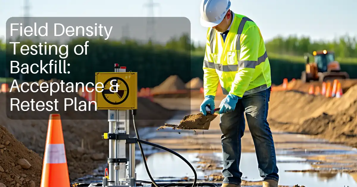
QA/QC Requirements
Acceptance Criteria [Verify per project specifications]
- Degree of compaction (%DoC) relative to appropriate MDD:
- General/structural fill: ≥95% of MDD (ASTM D698 unless specified otherwise)
- Subgrade/formation/capping: ≥95–98% of MDD (project-specific)
- Subbase/base (unbound): ≥98% of MDD (typically Modified Proctor ASTM D1557)
- Moisture content window relative to OMC: typically −2% to +1% of OMC for cohesive soils; −3% to +2% for granular materials (project-specific).
Testing Frequency (typical benchmarks)
- General fill: minimum 1 test per 250 m³ or 1 per 500 m² per layer, whichever yields more tests
- Subgrade/formation: 1 per 250 m² per layer
- Capping/subbase: 1 per 250–500 m² per layer depending on criticality
- Additional: 1 confirmatory oven moisture for at least 1 in 10 nuclear tests or at start of each shift/material change
Calculations and Checks
- Dry density (sand-cone): γd = (Mw − Mw×w)/(Vh), where Mw is wet mass of recovered soil, w is gravimetric moisture, Vh is hole volume.
- Dry density (nuclear): per gauge output; apply project-approved bias/correction factors if established.
- %DoC = (γd(field) / MDD) × 100.
- Duplicate/replicate tolerance: field duplicates within ±30 kg/m³ dry density and ±0.5% moisture; otherwise investigate surface condition, seating, or method selection.
Method Selection Guidance
- Use sand-cone where nuclear use is restricted, near large metal structures, or where chemical composition affects nuclear moisture readings.
- Nuclear gauge preferred for rapid coverage and process control. For lifts thinner than 75–100 mm, readings may be unreliable; confirm by sand-cone or adjust method.
- Oversize correction: if retained on 37.5–50 mm sieve exceeds ~10–15% by mass, consider method limitations and apply correction or alternative verification [Verify].
Nonconformance and Corrective Action
- If result < specified %DoC or moisture outside tolerance: adjust moisture (wetting/drying), increase passes, recompact, or replace material. Define re-test frequency (e.g., minimum 1 test per 250 m² of treated area or as directed). Issue NCR/CAR and document closure with passing results.
Documentation and Traceability
- Each test linked to lot ID, coordinates, chainage/offset, material source, layer thickness, compaction plant, and weather conditions.
- Record equipment IDs, calibration due dates, and operator signatures.
- Submit daily summaries within 24 hours; maintain comprehensive register for monthly QA reporting.
Attachments
- Sample Field Density Report (sand-cone and nuclear)
- Daily Nuclear Gauge Standardization Log (with control limits)
- Calibration Certificates: gauge, balances, oven; radiation leak tests
- Approved Laboratory Proctor Curves and Summaries (per material source)
- RFI/IR Template for Test Location Approval
- Risk Assessment/Job Safety Analysis (including radiation controls)
- Manufacturer’s Operating Manual Excerpts (gauge)
- Training and Authorization Records for Operators
This content is a read-only public reference. Download or customize to get an editable version.
ITP preview
The first inspection activities from the linked ITP for Method Statement: In‑Situ Density and Moisture Content Testing of Earthworks Layers (Sand Replacement and Nuclear Methods):
| Activity | Inspection / Test | Acceptance Criteria | Responsibility | Record |
|---|---|---|---|---|
| Approval of method statement and ITP | Document review and approval | Approved documents prior to works | Project Manager / Engineer | Approved MS/ITP |
| Verification of Proctor reference | Check lab reports for MDD/OMC and compaction energy | Valid, approved Proctor for each material/source | QA/QC Engineer | Proctor reports |
| Daily equipment standardization/calibration checks | Gauge standard counts; balance zero; oven temperature | Within OEM/ASTM limits; certificates in date | Technician / QA | Daily check sheets; calibration certs |
Showing 3 of 8 inspection activities. View full ITP →
Related Inspection and Test Plan
An Inspection and Test Plan (ITP) is available for Method Statement: In‑Situ Density and Moisture Content Testing of Earthworks Layers (Sand Replacement and Nuclear Methods). The ITP defines the inspection activities, acceptance criteria, hold and witness points, responsible parties, and records required to verify the work described in this method statement.
View the Method Statement: In‑Situ Density and Moisture Content Testing of Earthworks Layers (Sand Replacement and Nuclear Methods) ITP →Frequently asked questions
Continue with related Quollnet resources connected to this method statement.