Method Statement: Subgrade Preparation and Compaction for Highway Construction – Method Statement
AI-assisted method statement with matching ITP, PDF download, and Excel export.
More than a static template
Unlike a downloadable Word or PDF template, this method statement is an AI-assisted editable starting point connected directly to a matching Inspection and Test Plan. Every section is structured, project-adaptable, and ready to export.
- AI-assisted drafting — Customize every section with AI for your specific project scope.
- Linked ITP — A matching inspection and test plan is generated alongside the method statement.
- Multiple export formats — Download as a formatted PDF or editable Excel spreadsheet.
- Editable starting point, not a final document — Review, verify, and adjust all content against your project requirements before use.
Static template vs. Quollnet workflow
| Feature | Static template | Quollnet |
|---|---|---|
| Project-specific content | Manual fill-in required | AI-assisted customization |
| Linked ITP | Separate document, no link | Matching ITP included |
| Export formats | Usually PDF only | PDF and Excel |
| Structured sections | Free-form layout | 13 standardized sections |
| Saved to your account | Local file only | Cloud-saved, reusable |
| Content accuracy | You verify everything | AI-assisted, you still verify |
| Cost | Often free but time-intensive | Free to customize and download |
What you can customize
When you save this method statement to your account, every section becomes editable. The following 13 sections are included:
- Scope — Defines the activity and its boundaries.
- References — Standards, specifications, and drawings.
- Responsibilities — Roles and accountabilities.
- Resources — Labour, plant, and equipment summary.
- Materials — Materials and compliance requirements.
- Equipment — Tools and equipment details.
- Prerequisites — Hold points and pre-conditions.
- Method sequence — Step-by-step construction sequence.
- Safety controls — HSE risk controls and PPE.
- Environmental controls — Environmental mitigation measures.
- QA/QC — Quality inspection and test requirements.
- ITP — Inspection and Test Plan table (has its own page).
- Attachments — Referenced drawings and documentation.
Why this method statement is used
This method statement is used to define and communicate the approved procedure for carrying out method statement: subgrade preparation and compaction for highway construction on site. It ensures the work is planned in advance, the correct resources and controls are in place, and all personnel understand responsibilities, sequence, quality requirements, and safety controls before work begins. It aligns site execution with the documented scope and acceptance expectations.
Who uses this method statement
This method statement is used by contractors, site supervisors, project engineers, QA/QC engineers, HSE officers, consultants, and client representatives. It serves as a shared reference for planning, execution, supervision, inspection, and approval of the activity on site.
When it is prepared and submitted
The method statement is prepared before the work activity starts and submitted as part of the pre-construction documentation package for review and approval.
Who reviews or approves it
The method statement is usually submitted to the client representative, consultant, resident engineer, or project management consultant for review and approval before the work commences.
Important approval note
This method statement is an AI-assisted editable starting point, not a pre-approved document. Before use on any project, all content must be reviewed and approved by the relevant parties (superintendent, principal contractor, or client representative) in accordance with your contract and project quality plan.
For example: if your specification requires a departure from a referenced standard, that departure must be documented and approved separately — this method statement will not capture that automatically. Always verify against your applicable drawings, specifications, and regulatory requirements.
Method statement content
Scope
Overview
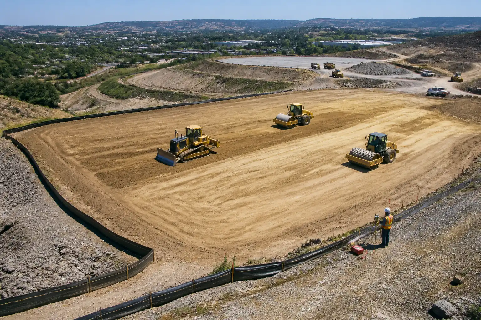
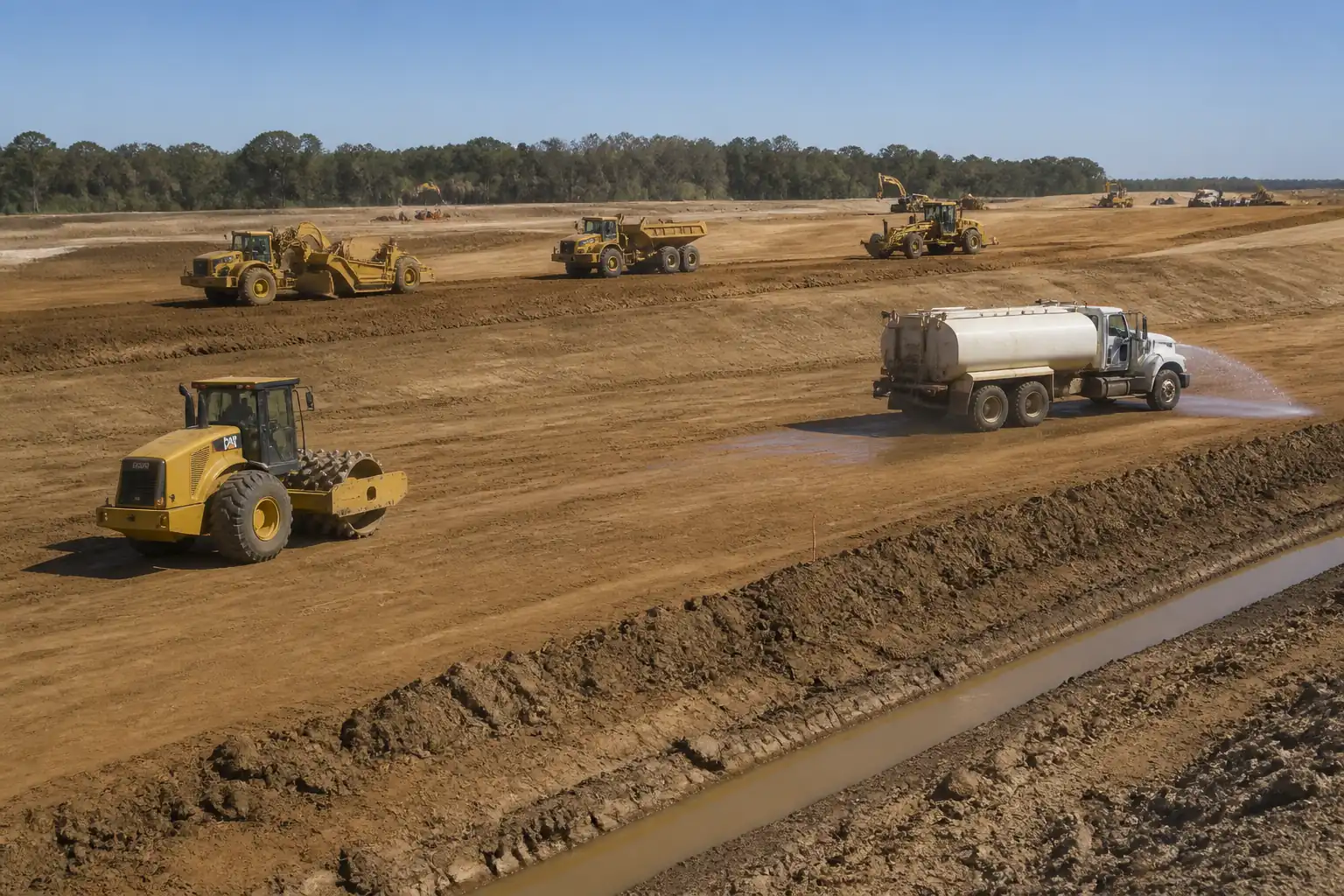
This method statement defines the procedures, quality requirements, HSE controls, and inspection/testing regime for the preparation and compaction of highway subgrade prior to sub-base placement. Activities include site clearing, formation trimming, proof rolling to identify soft spots, moisture conditioning, leveling, multi-pass rolling with vibratory compactors, in-situ density testing (Sand Cone/Nuclear gauge), level control checks, and inspection hold points leading to release for sub-base.
Extents
- Applies to all highway formation/subgrade areas within the Right-of-Way, including mainline lanes, shoulders, medians, on/off ramps, and tie-ins.
Objectives
- Achieve specified subgrade density and moisture conditions.
- Deliver design levels, crossfalls, and evenness tolerances.
- Identify and remediate weak/soft zones before sub-base.
- Establish documented acceptance through ITP hold/witness points.
Key Acceptance Targets [Verify per project specifications]
- Minimum in-situ dry density: Traffic lanes ≥98% of MDD (ASTM D1557/Modified Proctor); Shoulders/medians ≥95% of MDD.
- Moisture content: within ±2% of OMC from the governing Proctor curve.
- Level tolerance: ±20 mm from design; crossfall within ±0.5%.
- Surface evenness: ≤20 mm under a 3 m straightedge.
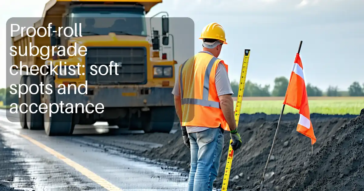
- Proof rolling: no pumping, no visible cracking, no rutting/deflection >25 mm.
Exclusions
- Chemical stabilization beyond local soft spot treatment (if full-area stabilization is required, a separate method statement applies).
References
| Document Type | Reference / Number | Revision | Notes |
|---|---|---|---|
| Standard | ASTM D1557 | ||
| Standard | ASTM D698 | Use only if contract specifies Standard Proctor for certain areas. | |
| Standard | ASTM D1556 | ||
| Standard | ASTM D6938 | Correlate to sand cone at frequency [Verify per project]. | |
| Standard | ASTM D4318 | ||
| Standard | ASTM D2487 | ||
| Standard | AASHTO T99/T180 | Use if project adopts AASHTO methods. | |
| Standard | BS EN 13286-2, -47 | Use per project specification region. | |
| Standard | EN 16907; EN 1997-1 | If applicable regionally. | |
| Standard | ISO 17123 series | ||
| Guideline | MUTCD [or local equivalent] | [Verify per project HSE plan and local regulations]. | |
| Contract | Project Specs | Controls numerical tolerances and testing frequencies if different. |
Responsibilities
| Role | Responsibility | Name / Party |
|---|---|---|
| PM | Approvals, liaison with Employer/Engineer, change control. | Contractor |
| CM/Site Agent | Sequencing, productivity, coordination of plant and crews. | Contractor |
| Engineer | Setting out, level checks, ITP sign-offs coordination. | Contractor |
| QA/QC | Lot definition, test requests, review of results, NCR/CAR. | Contractor |
| Technician | Proctor, sand cone, nuclear gauge ops, moisture tests. | Contractor/Third-Party Lab |
| HSE | Risk assessments, toolbox talks, inspections, permits. | Contractor |
| Surveyor | Benchmarks, TBMs, level grids, as-builts. | Contractor |
| Foreman | Implements sequence, coordinates rolling passes. | Contractor |
| Operators | Follow rolling patterns, speed, safety controls. | Contractor |
| Engineer Rep | Witness/Hold-point inspection; approval to proceed. | Engineer/Employer |
Resources
| Resource Type | Description | Quantity | Remarks |
|---|---|---|---|
| Personnel | 1 | ||
| Personnel | 1 | ||
| Personnel | 2–3 | Per front | |
| Personnel | 1 | ||
| Personnel | 1 per crew | ||
| Personnel | As required | Roller, grader, water truck, spotters |
Materials
| Material | Specification / Grade | Quantity | Remarks |
|---|---|---|---|
| Water | Clean water per project specs | As required | |
| Granular fill | CBR ≥20–30% at OMC [Verify] | As required | |
| Lime/Cement | Per ASTM/EN for soil stabilization [Verify] | As required | |
| Geotextile | EN ISO 10319/12236 compliant [Verify] | As required | |
| Survey consumables | N/A | As required |
Equipment
| Equipment | Capacity / Type | Quantity | Inspection Required |
|---|---|---|---|
| Grader | 150–200 HP | 1 | Daily pre-start |
| Vibratory roller | 10–14 t, 30–40 Hz | 1–2 | Daily pre-start |
| Padfoot roller | 12–20 t | 1 | Daily pre-start |
| PTR | 25–30 t, tyre pressure 550–700 kPa [Verify] | 1 | Daily pre-start |
| Water truck | 8–12 kL | 1–2 | Daily pre-start |
| Excavator | 20–30 t class | As required | Daily pre-start |
| Truck/PTR | 20–30 t GVW | 1 | Before use |
| Survey kit | Sets as needed | Calibration valid | |
| D1556/D6938 kits | 1 set each | Per standard |
Prerequisites
Approvals and Inputs
- Approved ITP and this Method Statement available on site.
- Latest Issued For Construction (IFC) drawings and cross-sections.
- Laboratory Proctor curves (ASTM D1557 unless otherwise specified) for each soil type/lot.
- Approved borrow/source data and material submittals for replacement granular, geotextile, stabilizers (if any).
Site Readiness
- Utility clearance: Completed by competent utility locator; permits and as-built records reviewed. Mark and protect all services.
- Traffic Management Plan: Implemented for work zones, signage, delineation, and plant crossings [Verify per project HSE plan and local regulations].
- Survey control: Primary control points and TBMs established and verified; working benchmarks protected.
- Weather/ground conditions: Work planned to avoid over-wet conditions; stop rules and contingency defined for rainfall events.
Plant/People Readiness
- Plant pre-start inspections completed; rollers set to required ballast/tyre pressure [Verify].
- Calibration: Nuclear gauge within validity; sand-cone apparatus verified; survey instruments calibrated (ISO 17123 practices).
- Competency: Operators licensed; testers certified; crew briefed via task-specific toolbox talk.
Lot Definition
- Define logical lots by chainage, width, and layer (e.g., 200–500 m lengths per lane) prior to testing and record on ITP.
Hold Points Communicated
- H1: Pre-start readiness and survey verification
- H2: Formation after trimming, before proof rolling
- H3: After proof rolling and remediation, prior to compaction
- H4: Post-compaction density/level results, prior to sub-base release
Method Sequence
| Step | Activity | Description | Responsibility | Inspection / Hold Point |
|---|---|---|---|---|
| 1 | Site clearing and stripping | Clear vegetation, debris, and strip topsoil/unsuitable material to the depth directed. Stockpile topsoil separately for reuse. | Foreman/Site Engineer | Visual by Engineer |
| 2 | Formation trimming and shaping | Trim to design formation level and crossfall using grader. Scarify high spots up to 150–200 mm as needed to achieve uniform layer. | Site Engineer/Surveyor | Survey check |
| 3 | Initial moisture assessment and conditioning | Assess moisture vs. OMC. Add water via bowser/spray bars or aerate by scarification to bring within OMC ±2%. Allow mellowing time for uniform distribution. | Foreman/QA-QC | Field moisture tests |
| 4 | Proof rolling (pre-compaction) | Proof roll entire formation using loaded truck (20–30 t GVW, 80–100 kN axle) or PTR at 3–5 km/h in overlapping passes to reveal soft areas. | Site Engineer/Foreman | HOLD POINT H2—Engineer to witness |
| 5 | Soft spot remediation (if encountered) | Undercut to firm stratum (typically 300–600 mm or as directed), dispose unsuitable, place approved granular in ≤200 mm loose lifts and compact, or apply localized lime/cement stabilization per design direction. | Site Engineer/Foreman | Engineer witness for extents |
| 6 | Layering and final moisture conditioning | Define working layer (top 150–200 mm). Adjust moisture to OMC ±2% uniformly through full depth using scarification and water addition or aeration. | Foreman/QA-QC | Moisture spot checks |
| 7 | Compaction—Breakdown passes | For cohesive soils, use padfoot in vibratory mode; for granular, use smooth drum vibratory. Start at edges moving to center for crowned roads. Maintain speed 3–5 km/h. | Foreman/Operators | QA/QC surveillance |
| 8 | Compaction—Intermediate passes | Continue with vibratory passes until target density trends are approached. Use PTR to knead and close surface as appropriate. | Foreman/Operators | |
| 9 | Compaction—Finishing passes and trimming | Switch to static mode/light vibration for final passes. Final trim with grader as necessary. | Site Engineer/Operators | Survey check |
| 10 | In-situ density and moisture testing | Perform field density by Sand Cone (ASTM D1556) as referee and/or Nuclear Gauge (ASTM D6938) with correlation. Minimum frequency: ≥1 test per 500 m² per layer per lot, minimum 3 tests/lot [Verify]. Take matching moisture tests. | QA/QC Engineer/Lab Tech | HOLD POINT H4—test results review |
| 11 | Proof rolling (post-compaction, if required by spec) | Re-proof roll compacted formation to confirm stability, especially at transitions/tie-ins. | Site Engineer | Engineer witness (as specified) |
| 12 | Protection and handover for sub-base | Protect finished subgrade from traffic and moisture extremes. Install temporary seals if required. Request Engineer’s release for sub-base placement. | Site Engineer/QA-QC | HOLD POINT—release to next trade |
Health, Safety, and Environment (HSE) — Task-Specific Safety Controls
Key Hazards and Controls
- Hazard: Underground utility strike during trimming/undercut
- Consequence: Electrocution, gas release, service outage
- Engineering/Procedural Control: Utility clearance with latest as-builts; locate with GPR/cable locator; pothole by hand/vacuum; establish exclusion zones and permit-to-dig.
- Required PPE: Helmet, gloves, safety boots, eye protection; dielectric gloves if electrical work [Verify].
- Collective Measure: Marked corridors, barriers, and spotter during excavation.
-
Inspection/Permit: Permit-to-dig; Supervisor sign-off; utility owner coordination.
-
Hazard: Plant–pedestrian interface (rollers, graders, trucks)
- Consequence: Struck-by, crushing
- Engineering/Procedural Control: Segregated pedestrian routes; banksman/spotter; reversing alarms and beacons; no-go zones around rollers; UHF radio comms.
- PPE: High-visibility vest, hard hat, boots, gloves.
- Collective Measure: Temporary barriers, cones, flaggers per TMP.
-
Inspection/Permit: Daily plant pre-starts; traffic management inspection.
-
Hazard: Roller overturn or ground collapse on weak edges/embankments
- Consequence: Serious injury/fatality, equipment damage
- Engineering/Procedural Control: Maintain safe offset from edges (≥1.0 m or greater per geotech advice); assess bearing by proof rolling; avoid high vibration near unsupported edges; ramp transitions.
- PPE: Seat belts, high-vis, boots.
- Collective Measure: Edge delineation and berms; spotter when near edges.
-
Inspection/Permit: Supervisor authorization; equipment inspection.
-
Hazard: Excessive ground vibration near structures/services
- Consequence: Damage to utilities/structures; complaints
- Engineering/Procedural Control: Reduce amplitude/switch to static; increase stand-off distances; vibration monitoring if required.
- PPE: Standard PPE
- Collective Measure: Exclusion zones; monitoring devices.
-
Inspection/Permit: Vibration monitoring logs; Engineer instruction.
-
Hazard: Dust generation during scarification/compaction
- Consequence: Respiratory irritation, visibility reduction, environmental nuisance
- Engineering/Procedural Control: Pre-wet surfaces; water carts; limit drop heights; halt in high winds.
- PPE: Dust masks (P2/P3) when visible dust persists.
- Collective Measure: Speed limits; wheel wash.
-
Inspection/Permit: Environmental inspection records.
-
Hazard: Noise >85 dB(A) from vibratory plant
- Consequence: Hearing loss
- Engineering/Procedural Control: Maintain mufflers; schedule exposure; rotate crews; use low-noise settings when possible.
- PPE: Hearing protection (earplugs/earmuffs).
- Collective Measure: Acoustic barriers where practicable.
-
Inspection/Permit: Noise monitoring if required.
-
Hazard: Working adjacent to live traffic
- Consequence: Vehicle collision
- Engineering/Procedural Control: TMP with lane closures, tapers, crash barriers; flaggers; work during off-peak.
- PPE: Class-compliant high-vis, cut-resistant gloves, boots.
- Collective Measure: Approved road traffic control devices per MUTCD/local.
-
Inspection/Permit: Traffic permit/approval; daily checks.
-
Hazard: Manual handling of test equipment (sand-cone, trays)
- Consequence: Musculoskeletal injury
- Engineering/Procedural Control: Use trolleys; team lifts; stage equipment close to test points.
- PPE: Gloves, boots.
- Collective Measure: Ergonomic training/toolbox talk.
-
Inspection/Permit: HSE inspections; training records.
-
Hazard: Hot/cold stress and dehydration
- Consequence: Heat exhaustion/hypothermia
- Engineering/Procedural Control: Work-rest cycles; shade/heated shelters; hydration plan; weather monitoring.
- PPE: Weather-appropriate PPE; sunscreen.
- Collective Measure: Cool/heat stations; first aid.
-
Inspection/Permit: HSE monitoring; stop-work for extreme weather [Verify per project HSE plan and local regulations].
-
Hazard: Contaminated or soft ground collapse during undercut
- Consequence: Entrapment, slips
- Engineering/Procedural Control: Avoid over-excavation; batter/shore sides where needed; restrict access.
- PPE: Boots with good tread, gloves, helmets.
- Collective Measure: Barricade with signage.
- Inspection/Permit: Supervisor sign-off; excavation permit if depth/conditions require.
General Requirements
- Mandatory pre-start briefing covering sequence, plant routes, hold points, and emergency procedures.
- Only competent, authorized operators to run plant; seat belts mandatory.
- All controls to be verified against Project HSE Plan and local regulations.
Environmental Controls
Key Environmental Risks and Controls
- Dust Emissions
- Control: Pre-wet formation; continuous water carts; reduce speeds to ≤20 km/h in work zone; suspend works in high winds.
-
Monitoring: Visual inspections; complaint log review.
-
Sediment Runoff and Erosion
- Control: Perimeter silt fences, straw wattles, temporary berms; avoid directing water to unprotected drains; staged works to limit exposed areas.
-
Monitoring: Post-rain inspections; maintain erosion/sediment controls.
-
Water Use and Discharge
- Control: Meter water use where required; prevent ponding; manage discharge to designated points; no discharge of turbid water without treatment [Verify].
-
Monitoring: Discharge turbidity/clarity checks if stipulated.
-
Noise and Vibration
- Control: Maintain equipment; avoid night operations unless permitted; limit vibration settings near receptors; install temporary acoustic screens where practical.
-
Monitoring: Noise/vibration monitoring if required by permit.
-
Waste and Spoil Management
- Control: Segregate topsoil for reuse; dispose unsuitable material to approved tip with haul permits; prevent spill from trucks (cover loads).
-
Monitoring: Waste transfer notes; tip receipts.
-
Hydrocarbon and Chemical Spills
- Control: Refuel in designated bunded area; spill kits on plant; immediate containment and cleanup.
-
Monitoring: Spill log; weekly inspection of refueling points.
-
Protection of Flora/Fauna and Watercourses
- Control: Respect exclusion zones; no stockpiles within [25–50] m of waterways unless protected [Verify]; rapid stabilization of exposed areas.
-
Monitoring: Environmental walkdowns; photo records.
-
Archaeology/Heritage Chance Finds
- Control: Stop work, protect area, notify Engineer/Authorities.
- Monitoring: Induction includes procedure.
Quality Assurance / Quality Control
Quality Objectives
- Achieve specified density, moisture, level, crossfall, and evenness criteria prior to sub-base.
Lotting and Testing Frequencies [Verify per project specifications]
- Lot size: Define by uniform soil type and work front (e.g., 200–500 m length per lane). Minimum 3 density tests per lot.
- Density testing: ≥1 per 500 m² per layer; increase frequency for variable conditions or after rework.
- Referee method: Sand Cone (ASTM D1556). Nuclear gauge (ASTM D6938) allowed with correlation (at least 1 sand cone per 5 nuclear readings initially; adjust per approved correlation plan).
- Moisture testing: 1 per density test minimum (ASTM D2216 oven-dry or D4944 speedy).
- Level checks: Grid or stringline at 25 m intervals per lane and at edges; additional checks at transitions.
- Optional stiffness checks: DCP 1 per 2,500 m² if specified.
Acceptance Criteria [Typical—Verify]
- Density: Traffic lanes ≥98% MDD (ASTM D1557); Shoulders/medians ≥95% MDD.
- Moisture: OMC ±2% at time of compaction/testing.
- Levels: ±20 mm; crossfall within ±0.5%.
- Evenness: ≤20 mm under a 3 m straightedge in any direction.
- Proof rolling: No pumping; no visible cracking; rutting/deflection ≤25 mm.
- Lift thickness: ≤200 mm loose per compaction layer (unless otherwise approved).
Calibration and Records
- Nuclear gauge: Calibration and leak test current; correlation documented; daily standard counts recorded.
- Sand cone: Cones and sand calibrated; density of sand verified.
- Survey: Instrument calibration certs current; backsight checks recorded.
- Records: ITP checklists, test reports, survey sheets, proof-rolling logs, NCR/CAR (if any), Engineer approvals.
Nonconformance and Corrective Action
- If any acceptance criterion fails: Identify lot boundaries, stop subsequent layer placement, investigate cause (moisture, lift thickness, equipment settings), recondition (scarify, adjust moisture), re-compact, and re-test. Document via NCR and close-out with evidence.
Protection of Finished Subgrade
- Restrict traffic; maintain drainage; re-proof/re-test after heavy rainfall or if surface dries/cracks before sub-base placement.
Attachments
- Approved ITP for Subgrade Preparation and Compaction
- Latest IFC drawings and setting-out data
- Proctor (ASTM D1557) lab reports for each soil type/borrow source
- Calibration certificates: Nuclear gauge (incl. leak test), sand cone apparatus, survey instruments
- Traffic Management Plan and permits
- HIRA/Task Risk Assessment for subgrade works
- Manufacturer data sheets: rollers, geotextiles (if used), stabilizers (if used)
- Proof-rolling log template; density test forms; survey check sheets
- NCR/CAR templates and sample close-outs
- Environmental management plan excerpts relevant to earthworks
This content is a read-only public reference. Download or customize to get an editable version.
ITP preview
The first inspection activities from the linked ITP for Method Statement: Subgrade Preparation and Compaction for Highway Construction:
| Activity | Inspection / Test | Acceptance Criteria | Responsibility | Record |
|---|---|---|---|---|
| Pre-start documentation | Check approvals, Proctor curves, TMP, permits | Approvals in place; current Proctor for soil types; permits active. | QA/QC Engineer | Pre-start checklist |
| Survey control verification (HOLD) | TBM check, control traverse, instrument calibration | Control within tolerances; instruments calibrated. | Site Engineer/Surveyor; Engineer Rep (Witness) | Survey verification report |
| Site clearing/stripping | Visual inspection | Formation free of organic/unsuitable material. | Site Engineer | Inspection record; photos |
Showing 3 of 12 inspection activities. View full ITP →
Related Inspection and Test Plan
An Inspection and Test Plan (ITP) is available for Method Statement: Subgrade Preparation and Compaction for Highway Construction. The ITP defines the inspection activities, acceptance criteria, hold and witness points, responsible parties, and records required to verify the work described in this method statement.
View the Method Statement: Subgrade Preparation and Compaction for Highway Construction ITP →Frequently asked questions
Continue with related Quollnet resources connected to this method statement.