Method Statement: Permanent Reinstatement of Utility Trench Openings in Roadways and Footpaths – Method Statement
AI-assisted method statement with matching ITP, PDF download, and Excel export.
More than a static template
Unlike a downloadable Word or PDF template, this method statement is an AI-assisted editable starting point connected directly to a matching Inspection and Test Plan. Every section is structured, project-adaptable, and ready to export.
- AI-assisted drafting — Customize every section with AI for your specific project scope.
- Linked ITP — A matching inspection and test plan is generated alongside the method statement.
- Multiple export formats — Download as a formatted PDF or editable Excel spreadsheet.
- Editable starting point, not a final document — Review, verify, and adjust all content against your project requirements before use.
Static template vs. Quollnet workflow
| Feature | Static template | Quollnet |
|---|---|---|
| Project-specific content | Manual fill-in required | AI-assisted customization |
| Linked ITP | Separate document, no link | Matching ITP included |
| Export formats | Usually PDF only | PDF and Excel |
| Structured sections | Free-form layout | 13 standardized sections |
| Saved to your account | Local file only | Cloud-saved, reusable |
| Content accuracy | You verify everything | AI-assisted, you still verify |
| Cost | Often free but time-intensive | Free to customize and download |
What you can customize
When you save this method statement to your account, every section becomes editable. The following 13 sections are included:
- Scope — Defines the activity and its boundaries.
- References — Standards, specifications, and drawings.
- Responsibilities — Roles and accountabilities.
- Resources — Labour, plant, and equipment summary.
- Materials — Materials and compliance requirements.
- Equipment — Tools and equipment details.
- Prerequisites — Hold points and pre-conditions.
- Method sequence — Step-by-step construction sequence.
- Safety controls — HSE risk controls and PPE.
- Environmental controls — Environmental mitigation measures.
- QA/QC — Quality inspection and test requirements.
- ITP — Inspection and Test Plan table (has its own page).
- Attachments — Referenced drawings and documentation.
Why this method statement is used
This method statement is used to define and communicate the approved procedure for carrying out method statement: permanent reinstatement of utility trench openings in roadways and footpaths on site. It ensures the work is planned in advance, the correct resources and controls are in place, and all personnel understand responsibilities, sequence, quality requirements, and safety controls before work begins. It aligns site execution with the documented scope and acceptance expectations.
Who uses this method statement
This method statement is used by contractors, site supervisors, project engineers, QA/QC engineers, HSE officers, consultants, and client representatives. It serves as a shared reference for planning, execution, supervision, inspection, and approval of the activity on site.
When it is prepared and submitted
The method statement is prepared before the work activity starts and submitted as part of the pre-construction documentation package for review and approval.
Who reviews or approves it
The method statement is usually submitted to the client representative, consultant, resident engineer, or project management consultant for review and approval before the work commences.
Important approval note
This method statement is an AI-assisted editable starting point, not a pre-approved document. Before use on any project, all content must be reviewed and approved by the relevant parties (superintendent, principal contractor, or client representative) in accordance with your contract and project quality plan.
For example: if your specification requires a departure from a referenced standard, that departure must be documented and approved separately — this method statement will not capture that automatically. Always verify against your applicable drawings, specifications, and regulatory requirements.
Method statement content
Scope
Overview
This method statement defines the permanent reinstatement of utility trench openings in carriageways and footpaths following completion of utility installation/repair works. It covers subgrade proofing, backfilling and compaction, granular sub-base placement, asphalt or concrete pavement restoration, joint treatment/sealing, surface finishing and matching, road marking reinstatement (if applicable), and quality control testing (density, levels, evenness).
Locations
- Carriageways (asphalt or concrete)
- Footpaths/footways (asphalt or concrete)
Exclusions
- Reinstatement of block/segmental paving (can be added by addendum)
- Structural slab restoration beyond pavement function unless specified
Objectives
- Restore structural capacity and ride quality equivalent to or better than existing adjacent pavement.
- Match levels, crossfall/camber, texture, and joint pattern of surrounding surface within specified tolerances [Verify per project specifications].
Key Performance Targets [Verify per project specifications]
- Compaction: Backfill and sub-base to ≥95–98% MDD (per specified Proctor method).
- Asphalt density: 92–97% of maximum theoretical density (Gmm) or ≥95% Marshall density equivalent.
- Concrete strength: Achieve specified 28‑day compressive strength (typical 30–40 MPa for pavement grade).
- Level tolerance: Footpaths ±6 mm; Carriageways ±10 mm relative to adjacent surface and drainage plan.
- Evenness: Deviation under straightedge typically ≤6–10 mm over 3 m (class dependent).
- Joint seal: Continuous, watertight, within specified width/overband limits.
References
| Document Type | Reference / Number | Revision | Notes |
|---|---|---|---|
| UK SROH (latest) [Verify applicability] | Edge sealing, layer thicknesses, tolerances, and testing frequencies. | ||
| BS EN 13108 series / BS 594987 (asphalt paving) | Mixture classes (e.g., AC 20, AC 10), laying and compaction guidance. | ||
| BS EN 206 + BS 8500 / ACI 330R (concrete pavements) | Pavement-grade concrete, curing, joints. | ||
| ASTM D698/D1557, ASTM D6938, ASTM D1556; or BS 1377 / BS EN ISO 17892 | Proctor density and in-situ density by nuclear gauge or sand-cone. | ||
| BS EN 12697 series; AASHTO T 209 (Gmm) | Compaction, core density, temperature, voids. | ||
| BS EN 12591 (Bitumen), BS EN 13808 (Emulsions) | Edge seal/tack coat properties. | ||
| BS EN 14188-1/-2 | Hot or cold applied joint sealants. | ||
| ISO 9001, ISO 14001, ISO 45001 | Management systems integration [Verify per project HSE plan and local regulations]. | ||
| Manual on Uniform Traffic Control Devices (MUTCD) / Chapter 8 (UK) or local code | Temporary traffic control near works [Verify per local authority]. |
Responsibilities
| Role | Responsibility | Name / Party |
|---|---|---|
| Project Manager | Overall delivery, approvals, resources, programme, liaison with road authority. | Main Contractor |
| Site Engineer | Set out, verify levels and crossfall, supervise reinstatement sequence, confirm layer thicknesses. | Main Contractor |
| Traffic Management Supervisor | Implement TMP, barricading, signage, access/egress, night works lighting. | Main Contractor |
| HSE Officer | Ensure HSE controls, permits to dig/hot works, task briefings, monitoring of HAVS/noise/exposure. | Main Contractor |
| QA/QC Engineer | Inspection & testing plan execution, ITP holds/witnesses, materials approvals, records control. | Main Contractor |
| Foreman & Crew | Operate compaction equipment, place materials per method, protect finished surfaces. | Main Contractor |
| Materials Technician / Laboratory | Nuclear density testing, asphalt temperature checks, core extraction, concrete tests. | Approved Lab |
| Asphalt Subcontractor | Supply and lay asphalt mixes to specification, compaction and joints. | Specialist |
| Concrete Subcontractor | Supply, place, finish and cure concrete; saw-cut joints; install sealant. | Specialist |
| Engineer/Client Representative | Inspection/acceptance at hold points and final handover. | Engineer/Authority |
Resources
| Resource Type | Description | Quantity | Remarks |
|---|---|---|---|
| Crew – Carriageway asphalt reinstatement | 1 Foreman, 4–6 operatives, 1 roller operator, 1 paver operator (or hand-lay team) [Verify] | Adjust crew size to trench width/length and traffic control constraints. | |
| Crew – Footpath reinstatement | 1 Foreman, 2–3 operatives, 1 plate compactor operator [Verify] | ||
| Survey | 1 Surveyor with assistant as required | Levels/crossfall verification and as-built. | |
| Traffic management | TMP crew per lane closure requirement | Signs, cones, barriers, marshals [Verify per authority]. |
Materials
| Material | Specification / Grade | Quantity | Remarks |
|---|---|---|---|
| Granular Sub-base | BS EN 13285 / Local Type 1 specification [Verify] | Granular sub-base Type 1 or equivalent, well-graded, PI and Los Angeles Abrasion within spec. | |
| Selected Backfill | As per SROH/Project Spec; compaction target ≥95–98% MDD [Verify] | Selected backfill above utility surround; low-plasticity, free of organics/debris. | |
| Asphalt Binder/Base Course | BS EN 13108-1; Binder pen grade 40/60 or per mix design [Verify] | Dense graded asphalt binder/base (e.g., AC 20 dense bin). | |
| Asphalt Surface Course | BS EN 13108-1; PSV and texture to match existing [Verify] | Dense graded asphalt surface (e.g., AC 10 close/surface). | |
| Tack Coat / Edge Sealant | BS EN 13808 (Cationic emulsion) / Overband sealant per local highway spec [Verify] | Bitumen emulsion for tack/edge seal (e.g., K1-40) or polymer-modified sealer. | |
| Concrete | BS EN 206 + BS 8500; typical C32/40, exposure class XF/XC as applicable [Verify] | Pavement-grade concrete for footways/carriageways where rigid restoration is required. | |
| Curing Compound | ASTM C309 Type 2 or equivalent [Verify] | Membrane curing compound or wet cure materials. | |
| Joint Sealant (Concrete) | BS EN 14188-1 (cold-applied) or -2 (hot-poured), Class per project [Verify] | For concrete joints at tie-ins or panels. | |
| Pipe Bedding/Sand | Grading per utility standard detail [Verify] | For bedding/surround to utility as specified by utility owner. |
Equipment
| Equipment | Capacity / Type | Quantity | Inspection Required |
|---|---|---|---|
| Plate Compactor | 60–120 kg class [Verify] | ||
| Trench Rammer (Wacker) | 11–15 kN [Verify] | ||
| Tandem Roller | 6–10 t [Verify] | ||
| Tandem Roller (Small) | 1.5–3 t [Verify] | ||
| Asphalt Paver/Hotbox | Hotbox 3–8 t insulated [Verify] | ||
| Floor Saw / Cut-off Saw | 350–500 mm blade with water feed | ||
| Milling/Planer (small) | 300–500 mm drum [Verify] | ||
| Nuclear Density Gauge | ASTM D6938 calibrated | ||
| Automatic Level / Total Station | ±2 mm accuracy [Verify] | ||
| Infrared Thermometer | -20 to 300°C | ||
| Concrete Test Kit | ASTM C143/C231/C39 or BS equivalents | ||
| Traffic Management Equipment | Per approved TMP |
Prerequisites
- Approved Method Statement, ITP, and Risk Assessment/Method Statement (RAMS).
- Permit to dig and utility owner clearance confirming completion of utility works and allowable backfill materials [Verify per project HSE plan and local regulations].
- Approved Traffic Management Plan (TMP) and road authority consents (lane closure, working hours, noise permits).
- Design details/standard reinstatement drawings showing required layer thicknesses for the specific road class and footway type [Verify per project specifications].
- Material approvals: asphalt mix design certificates (BS EN 13108), concrete mix submittals (BS EN 206/BS 8500), joint sealant data sheets, sub-base certificates of compliance.
- Calibration/valid certification: nuclear density gauge, scales, thermometers, rollers/compactometers, slump cones.
- Weather check: no asphalt laying during rain or when surface is wet/contaminated; ambient and surface temperatures within specification [Verify].
- Underground services confirmation drawings and CAT/Genny scan ahead of any trimming/saw-cutting.
- Pre-start coordination meeting and task briefing to crews; confirm sequence and hold points.
- Public notification and access arrangements for residents/businesses where required.
- Environmental controls in place (spill kits, dust suppression, waste containers).
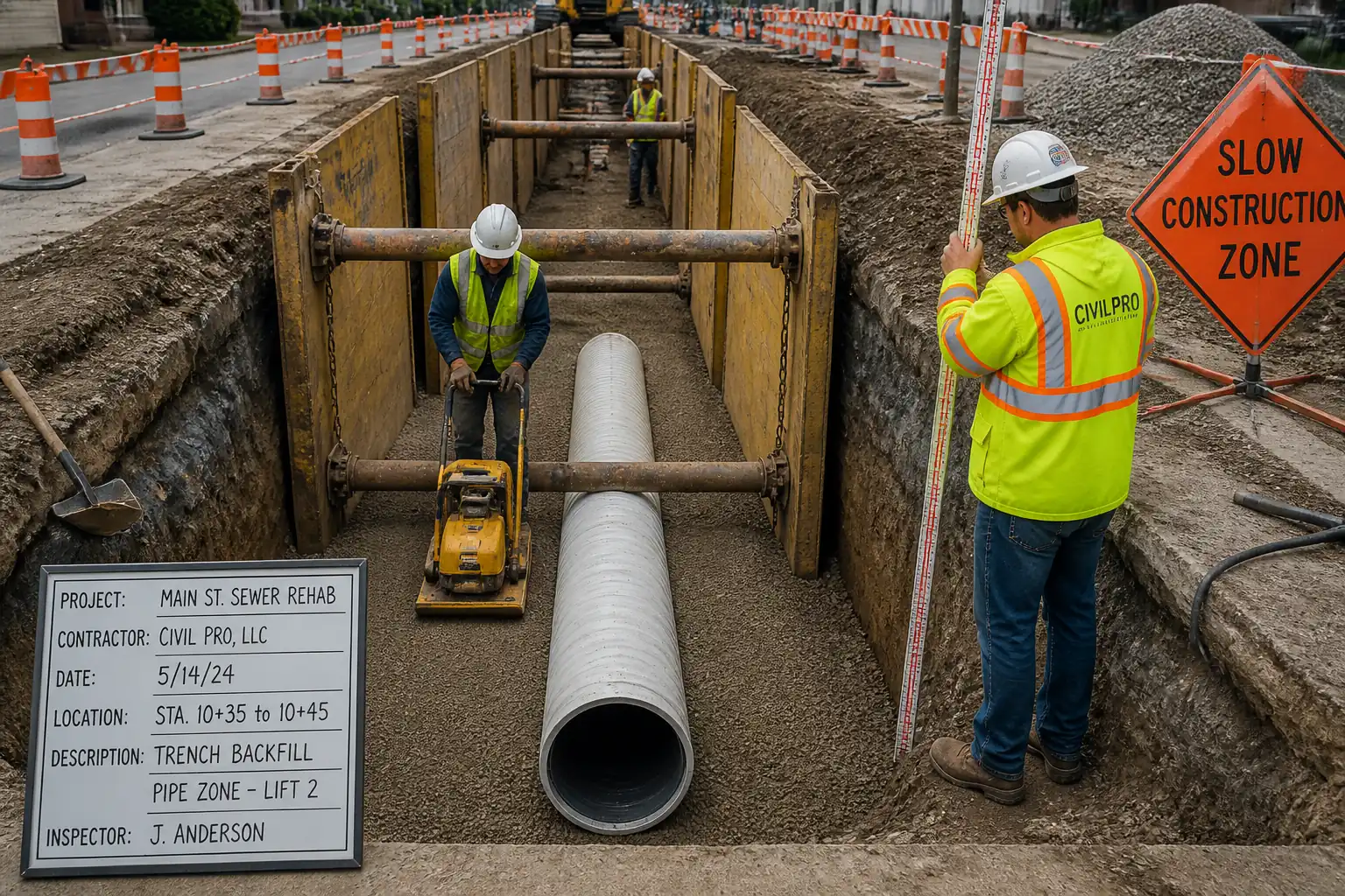
Method Sequence
| Step | Activity | Description | Responsibility | Inspection / Hold Point |
|---|---|---|---|---|
| 1 | Site setup and traffic management | Implement TMP: signs, cones, barriers, lighting, pedestrian diversions. Establish exclusion zones and safe plant-pedestrian interfaces. | Traffic Management Supervisor/Foreman | |
| 2 | Survey and mark-out | Confirm trench extents and layer build-ups. Mark neat reinstatement cut lines minimum 150 mm beyond disturbed edges or per authority standard. | Site Engineer | |
| 3 | Edge saw-cut and trimming | Saw-cut pavement edges full depth of the course to be reinstated with water suppression. Remove loose/undermined material to sound substrate. | Foreman | |
| 4 | Subgrade exposure and proof-rolling | Excavate loose/degraded material. Proof-roll with small roller/plate. Identify soft spots and over-excavate/replace with compacted sub-base. | Foreman/Site Engineer | |
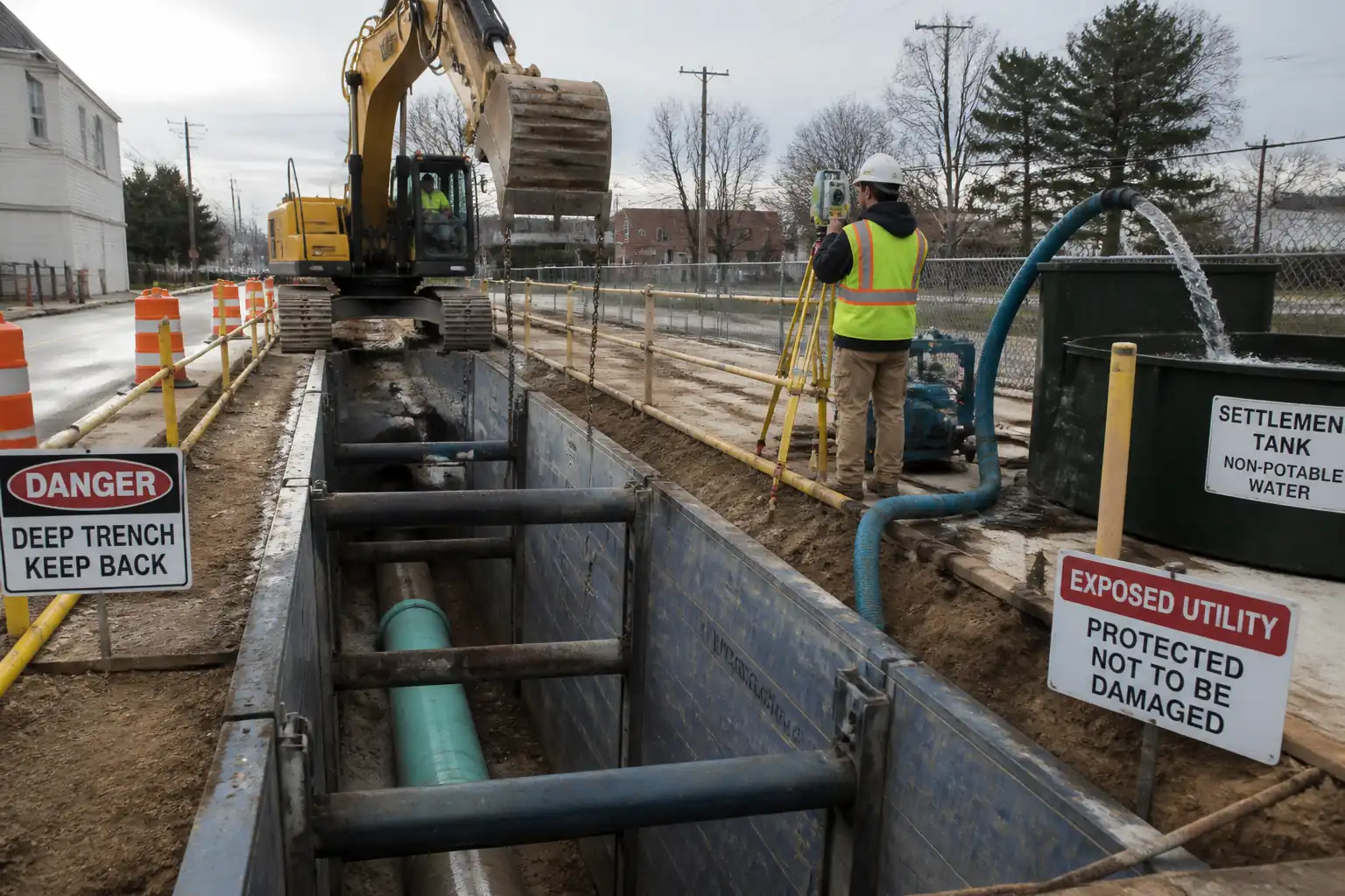
| 5 | Utility bedding/surround (if required) | Place and compact bedding and surround per utility standard (e.g., 100 mm bedding, 150 mm surround above crown) without damaging utility. | Foreman | |
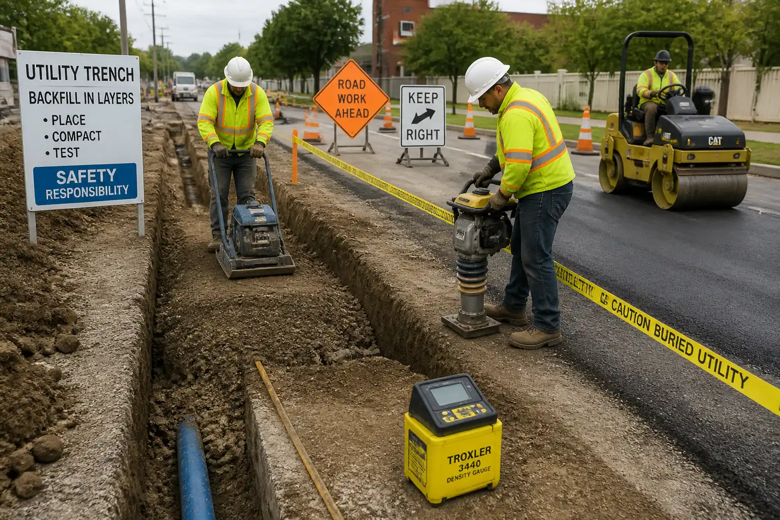
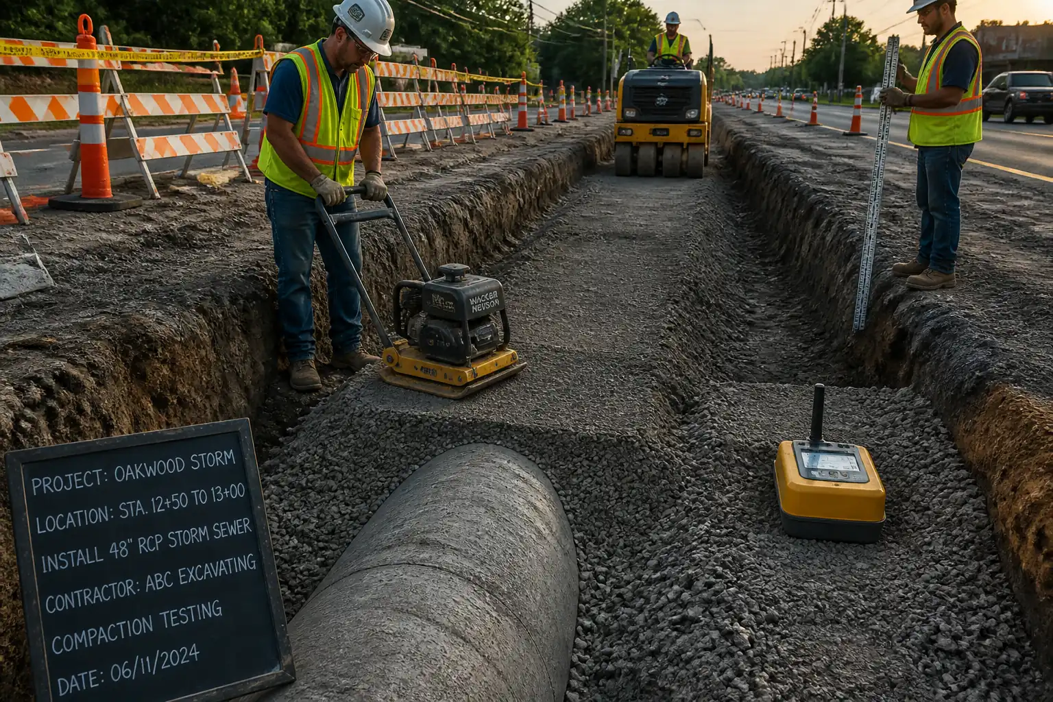
| 6 | Layered backfill placement | Place selected backfill in uniform lifts (typically 150–200 mm). Compact with plate/rammer avoiding utility damage. Moisture near OMC. | Foreman/QA-QC | |
| 7 | Sub-base placement and compaction | Place Type 1 sub-base to specified thickness (typ. 100–225 mm depending on road class). Compact in ≤150 mm lifts. | Foreman/QA-QC | |
| 8 | Preparation for asphalt or concrete | Clean and dry surface. For asphalt: apply tack to vertical edges and horizontal interface. For concrete: dampen base (SSD) and install dowels/tie bars if specified. | Foreman/Site Engineer | |
| 9A | Asphalt binder/base course laying | Place binder/base course (e.g., AC 20) to thickness matching existing layer. Lay temperature within mix design; compact with roller sequence (edge-first). | Asphalt Subcontractor | |
| 9B | Concrete placement (alternative to 9A/10A) | Place concrete to required slab thickness. Vibrate to consolidate, finish to match texture, apply curing compound. Form or saw contraction joints as specified. | Concrete Subcontractor | |
| 10A | Asphalt surface course laying | Apply tack. Lay surface course (e.g., AC 10). Compact to achieve density. Ensure surface matches surrounding profile and texture. | Asphalt Subcontractor | |
| 11 | Joint sealing/overbanding | Seal longitudinal and transverse joints. For asphalt: hot-applied edge seal and overband (typ. 25–50 mm width, 1–2 mm thick) within authority limits. For concrete: clean, prime, and apply sealant to designed width/depth with backer rod where needed. | Foreman/Subcontractor | |
| 12 | Finishing, ironworks, and surface matching | Adjust frames/covers if within reinstatement; match crossfall/camber; broom or texture to blend; reinstate road markings if affected. | Site Engineer/Foreman | |
| 13 | Curing and opening to traffic | Asphalt: allow cooling to ambient (<45°C) before opening. Concrete: maintain curing; open after achieving specified strength or minimum curing time. | Foreman/QA-QC | |
| 14 | Demobilisation and handover | Remove TMP, clean site, dispose waste to licensed facilities, submit test results and as-builts. | Project Manager/QA-QC |
Safety Controls (HSE)
Task-specific hazards and controls
- Hazard: Underground service strike during trimming/compaction
- Likely consequence: Electrocution, gas release, flooding, service outage.
- Engineering/procedural control: Permit-to-dig; latest utility survey and CAT/Genny scan; hand-dug trial holes around marked services; maintain minimum approach distances; use insulated tools near live services.
- Required PPE: Dielectric gloves where appropriate, safety boots with EH rating, eye protection, FR clothing if near electrical risks.
- Collective preventive measure: Physical barriers and spotter; service plans at point of work.
-
Inspection/permit/supervision: Permit-to-dig approval; supervisor sign-off before powered equipment near services; periodic re-scans.
-
Hazard: Live traffic interface and plant movement
- Likely consequence: Struck-by incidents, vehicle collisions.
- Engineering/procedural control: Approved TMP; positive separation (barriers), plant marshals, one-way plant routes, reversing alarms/cameras.
- Required PPE: Hi-vis Class 3, hard hat, boots, gloves.
- Collective preventive measure: Rigid barriers where speed >40 km/h; speed reduction measures.
-
Inspection/permit/supervision: Daily TMP inspection checklist; authority permits; night work lighting check [Verify per local regulations].
-
Hazard: Hot asphalt burns and fume exposure
- Likely consequence: Burns, respiratory irritation.
- Engineering/procedural control: Use insulated hotbox; controlled tipping; no walking on fresh mat; maintain upwind position; SDS briefing.
- Required PPE: Heat-resistant gloves, long sleeves, eye/face protection, respirator if inadequate ventilation [Verify].
- Collective preventive measure: Exclusion zone around paver/hotbox; first-aid burn kit on site.
-
Inspection/permit/supervision: Supervisor to verify temperatures and safe handling; check SDS.
-
Hazard: Silica/asphalt dust from saw-cutting/milling
- Likely consequence: Respiratory disease, eye injury.
- Engineering/procedural control: Water suppression and/or on-tool extraction; damp down; designated cutting area.
- Required PPE: FFP3/N95 respirator, goggles/face shield, hearing protection.
- Collective preventive measure: Screens to protect public; schedule cutting off-peak.
-
Inspection/permit/supervision: RPE fit testing; equipment dust control inspection.
-
Hazard: Noise and vibration (HAVS) from compactors and saws
- Likely consequence: Hearing loss, hand–arm vibration syndrome.
- Engineering/procedural control: Low-vibration tools; task rotation; exposure monitoring; maintain equipment.
- Required PPE: Hearing protection (SNR per site assessment), antivibration gloves (supplemental).
- Collective preventive measure: Acoustic barriers near sensitive receptors.
-
Inspection/permit/supervision: HAVS logs; noise monitoring per permit; equipment maintenance records.
-
Hazard: Manual handling of plates, cores, covers
- Likely consequence: Musculoskeletal injury.
- Engineering/procedural control: Use mechanical aids (lifting keys, hoists); team lifts; pre-lift planning.
- Required PPE: Gloves, boots.
- Collective preventive measure: Lifting A-frames or cover lifters for heavy ironwork.
-
Inspection/permit/supervision: Manual handling training records; lift plan where >50 kg.
-
Hazard: Wet concrete exposure and chemical burns
- Likely consequence: Skin/eye burns, dermatitis.
- Engineering/procedural control: Avoid skin contact; use wash stations; follow SDS; safe handling of curing compounds and sealants.
- Required PPE: Alkali-resistant gloves, eye protection, long sleeves, rubber boots.
- Collective preventive measure: Controlled pouring area and barriers.
-
Inspection/permit/supervision: COSHH/chemical handling permit where required; SDS available.
-
Hazard: Confined/limited width trenches
- Likely consequence: Trapping/crushing during compaction.
- Engineering/procedural control: Use appropriate-sized compaction plant; maintain escape route; operate from stable ground.
- Required PPE: Standard site PPE, with close-fitting clothing.
- Collective preventive measure: Banksman to control plant movements.
-
Inspection/permit/supervision: Supervisor to brief safe system for narrow works.
-
Hazard: Heat/cold and wet weather
- Likely consequence: Heat stress/hypothermia; poor compaction/adhesion.
- Engineering/procedural control: Weather cut-offs; shaded rest; warm/waterproof clothing; adjust rolling patterns.
- Required PPE: Weather-appropriate PPE.
- Collective preventive measure: Shelter and hydration points.
-
Inspection/permit/supervision: Supervisor to enforce weather criteria [Verify per project HSE plan].
-
General requirement: Emergency plan with spill response, first aiders, and contact numbers displayed.
Environmental Controls
- Dust control: Continuous water suppression for cutting/milling; minimize drop heights; sweep rather than blow. Monitor PM near sensitive receptors.
- Noise/vibration: Comply with working hours; use acoustic shrouds; maintain equipment; schedule high-noise tasks daytime; monitor as required by permit.
- Runoff management: Prevent slurry/asphalt fines entering drains. Use drain covers/silt socks. Collect saw-cut slurry for proper disposal.
- Waste management: Segregate asphalt, concrete, soil. Dispose to licensed facilities. Retain weighbridge tickets. Recycle milled asphalt where permitted.
- Materials handling: Store emulsions and fuels in bunded areas; spill kits within 20 m of workface; refuel over drip trays.
- Protection of existing features: Shield trees, street furniture, and ironwork from damage and bitumen overspray. Use geotextile/boards for protection.
- Light pollution: Directional task lighting; avoid spill to residences where practicable.
- Community liaison: Advance notice to residents/businesses; maintain safe pedestrian access.
- Compliance: Follow project CEMP and local environmental regulations [Verify per project HSE plan and local regulations].
QA/QC Requirements
Testing and Inspection
- In-situ density (backfill and sub-base): Nuclear gauge (ASTM D6938) or sand-cone (ASTM D1556). Frequency: minimum 1 test per 10 m trench length per lift, or 1 per 50 m² per lift; minimum 3 tests per lift per day [Verify]. Acceptance: ≥95–98% MDD per spec and layer type.
- Asphalt temperature: Check at truck arrival and during lay/rolling with IR thermometer; record every load and every 30 minutes [Verify temperatures per mix design].
- Asphalt density/voids: Cores or nuclear gauge. Typical frequency: 1 per 50–100 t or 1 per 100–200 m² per layer [Verify]. Acceptance: 92–97% of Gmm or ≥95% Marshall density equivalent; voids within design range.
- Asphalt thickness: Measure from cores or probes at edges; tolerance ±5–10 mm [Verify].
- Concrete tests: Slump (ASTM C143/BS EN 12350-2), air (ASTM C231/BS EN 12350-7), strength (ASTM C39/BS EN 12390-3). Frequency: 1 set per 50 m³ or per pour, min 1 set [Verify]. Early-opening strength per specification.
- Levels and evenness: Survey check at 5 m intervals and at joints. Straightedge 3 m: deviation typically ≤6–10 mm per class [Verify]. Finished level relative to adjacent surface: footway ±6 mm, carriageway ±10 mm [Verify].
- Tack/edge seal: Visual and application rate checks. No tracking, full coverage of edges.
- Joint seal: Continuity, width/thickness within standard (e.g., overband 25–50 mm width, 1–2 mm thickness) [Verify].
- Records: ITP forms, density sheets, temperature logs, delivery tickets, calibration certificates, concrete test reports, core logs, as-built survey.
Nonconformance and Corrective Action
- Any density/level deficiency: Delineate extent, re-compact or remove/replace affected layer; re-test until compliant.
- Segregated or cold asphalt: Remove and relay affected area, ensure proper joint preparation.
- Concrete surface defects: Grind high spots; repair honeycombing per repair procedure; reseal joints as necessary.
Hold/Witness Points (typical)
- Hold: Subgrade approval before backfill.
- Witness: Utility surround/backfill commencement.
- Hold: Sub-base compaction test acceptance.
- Witness: Pre-lay checks for asphalt/concrete including temperatures and tack.
- Hold: Concrete pour start and curing set-up (if concrete option).
- Hold: Final level/evenness and joint seal inspection before opening.
Documentation
- Maintain daily QA/QC checklist, photographs, test results, batch/mix tickets, and as-built drawings for submission to Engineer/Authority.
Attachments
- Standard reinstatement detail drawings (carriageway/footway) [Insert project references]
- Traffic Management Plan and layout drawings
- Daily QA/QC checklist (density, temperature, levels)
- Density test forms (ASTM/BS formats) and gauge calibration certificates
- Asphalt delivery tickets and mix compliance certificates
- Concrete mix design approvals and test report templates
- Joint sealant product data sheets and SDS
- Curing compound product data sheet and SDS
- Permit-to-dig and utility owner authorization
- As-built survey template and final acceptance form
This content is a read-only public reference. Download or customize to get an editable version.
ITP preview
The first inspection activities from the linked ITP for Method Statement: Permanent Reinstatement of Utility Trench Openings in Roadways and Footpaths:
| Activity | Inspection / Test | Acceptance Criteria | Responsibility | Record |
|---|---|---|---|---|
| Pre-works approvals and TMP setup | Check permits, method, ITP, TMP approvals; site signage/barriers in place | All approvals current; TMP implemented per plan | Project Manager / Traffic Supervisor / Engineer | Permit/TMP checklists, photos |
| Subgrade proof and approval | Visual/proof-roll; soft spot identification and treatment record | No rutting >10 mm; subgrade stable and dry; CBR adequate [Verify] | Engineer / QA-QC / Site Engineer | Inspection report, photos |
| Backfill layer compaction | In-situ density by nuclear gauge or sand-cone per lift | ≥95–98% MDD as specified; moisture near OMC | QA-QC / Lab Tech / Foreman | Density test results, calibration certs |
Showing 3 of 10 inspection activities. View full ITP →
Related Inspection and Test Plan
An Inspection and Test Plan (ITP) is available for Method Statement: Permanent Reinstatement of Utility Trench Openings in Roadways and Footpaths. The ITP defines the inspection activities, acceptance criteria, hold and witness points, responsible parties, and records required to verify the work described in this method statement.
View the Method Statement: Permanent Reinstatement of Utility Trench Openings in Roadways and Footpaths ITP →Frequently asked questions
Continue with related Quollnet resources connected to this method statement.