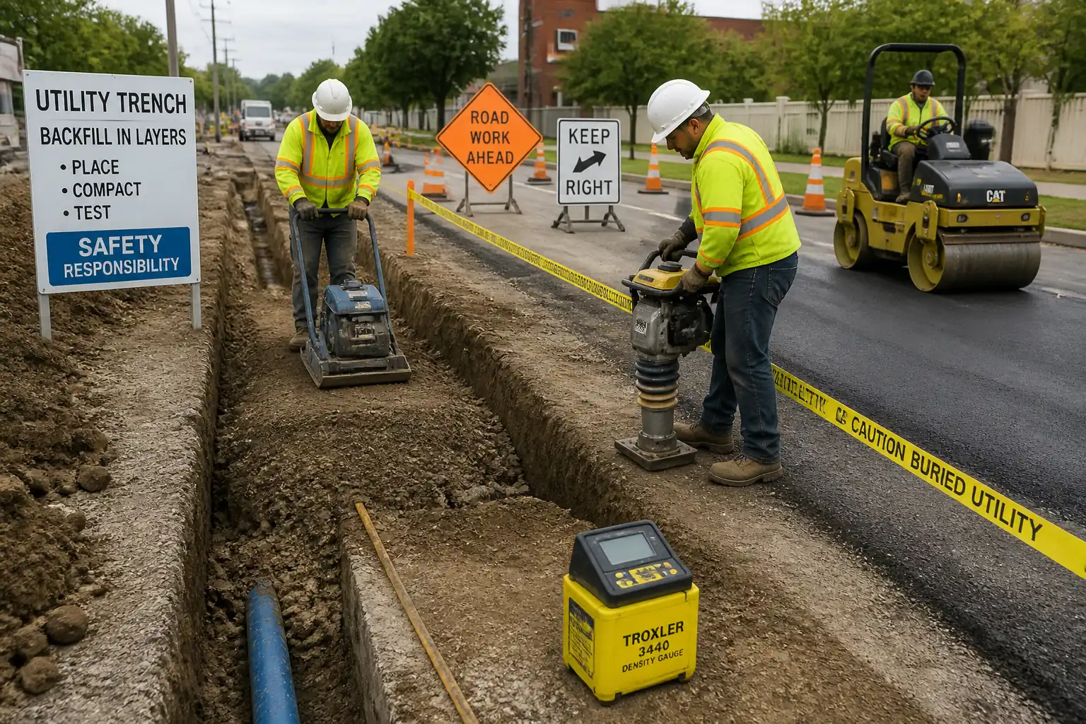
Inspection and Test Plan for Method Statement: Permanent Reinstatement of Utility Trench Openings in Roadways and Footpaths
AI-assisted inspection and test plan connected to a method statement, with PDF and Excel export.
More than a static template
Unlike a downloadable Word or PDF template, this ITP is an AI-assisted editable starting point directly connected to its method statement. Every inspection activity, hold point, and acceptance criterion is structured and ready to adapt to your project.
- AI-assisted customization — Tailor inspection activities and acceptance criteria to your specific project scope.
- Linked method statement — This ITP is connected to the corresponding method statement describing the work sequence.
- Multiple export formats — Download as a formatted PDF or editable Excel spreadsheet.
- Editable starting point, not a final document — Review and verify all content against your project specifications and standards before use.
What you can customize
When you save this ITP to your account, every inspection row becomes editable. You can add, remove, or modify:
- Inspection activity — Description of what is being inspected.
- Inspection type — Hold point (H), Witness point (W), Review (R), or Monitor (M).
- Responsibility — Contractor, subcontractor, engineer, or client.
- Frequency — How often the inspection occurs.
- Acceptance criteria — Referenced standard or specification requirement.
- Records — Forms, test reports, or checklists required as evidence.
Why this ITP is used
To verify each reinstatement layer and surface meets specification for strength, durability, and serviceability before opening to traffic.
Who uses this inspection and test plan
Site engineers, QA/QC staff, laboratory technicians, subcontractors, and the Engineer/Authority.
When this ITP is prepared and submitted
From pre-works approvals through subgrade, backfill, sub-base, paving or concrete works, to final acceptance.
Who receives or approves this ITP
Engineer/Authority for approval prior to works commencement.
Inspection scope
Permits and TMP, subgrade condition, compaction of each lift, asphalt temperatures/densities, concrete tests, joint sealing, levels and evenness, documentation.
Typical hold, witness, and review points
Holds at subgrade approval, sub-base acceptance, concrete pour start, final levels. Witness at backfill density tests, pre-paving checks, joint sealing.
Typical inspection records
Density reports, temperature logs, delivery tickets, concrete test results, core logs, surveys, inspection checklists, permits, as-builts.
Important approval note
This ITP is an AI-assisted editable starting point, not a pre-approved document. Before use on any project, all inspection activities, hold points, and acceptance criteria must be reviewed and approved by the relevant parties (superintendent, principal contractor, or client representative) in accordance with your contract and project quality plan.
Always verify acceptance criteria against your applicable drawings, specifications, and regulatory requirements. Hold points must be confirmed with the relevant authority before work proceeds past that point.
Inspection and test plan
| Activity | Inspection / Test | Acceptance Criteria | Responsibility | Record |
|---|---|---|---|---|
| Pre-works approvals and TMP setup | Check permits, method, ITP, TMP approvals; site signage/barriers in place | All approvals current; TMP implemented per plan | Project Manager / Traffic Supervisor / Engineer | Permit/TMP checklists, photos |
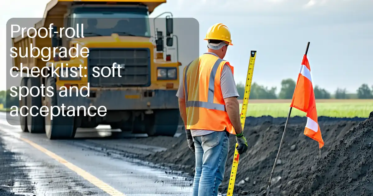
| Subgrade proof and approval | Visual/proof-roll; soft spot identification and treatment record | No rutting >10 mm; subgrade stable and dry; CBR adequate [Verify] | Engineer / QA-QC / Site Engineer | Inspection report, photos |
| Backfill layer compaction | In-situ density by nuclear gauge or sand-cone per lift | ≥95–98% MDD as specified; moisture near OMC | QA-QC / Lab Tech / Foreman | Density test results, calibration certs |
| Sub-base placement and compaction | Density testing; thickness/level check | Density ≥98% (carriageway) / ≥95% (footway) MDD [Verify]; level ±6 mm | QA-QC / Lab Tech / Engineer | Density sheets, survey records |
| Pre-paving checks (asphalt) | Edge/tack application, cleanliness, temperature of mix at delivery | Tack coverage 100%; delivery temp within mix design; edges clean/dry | QA-QC / Asphalt Subcontractor | Pre-lay checklist, temp log, delivery tickets |
| Asphalt compaction and density | Core density or nuclear density; thickness checks | 92–97% Gmm or ≥95% Marshall density [Verify]; thickness ±5–10 mm | QA-QC / Lab Tech | Core logs, density reports |
| Concrete placement (if applicable) | Slump, air, temperature; cylinders/cubes; curing application | Within approved mix limits; curing applied; strength at opening per spec | Engineer / QA-QC / Concrete Subcontractor | Concrete test reports, curing log |
| Joint sealing and overband | Visual and dimensional check of seal/overband | Continuous seal; width/thickness within authority limits; adhesion satisfactory | QA-QC / Foreman | Inspection sheet, photos |
| Levels/evenness and tie-in to ironwork | Survey and 3 m straightedge checks; ironwork level check | Level tolerance: footway ±6 mm; carriageway ±10 mm; evenness within class [Verify] | Site Engineer / QA-QC / Engineer | Survey log, straightedge checklist |
| Final acceptance and opening | Documentation review; visual inspection | All tests passed; surfaces clean; TMP removed safely | Engineer / Authority / PM | Handover certificate, as-builts |
This table is a read-only public reference. Download the PDF or Excel version, or customize this ITP to edit it for your project.
Frequently asked questions
Related method statement
This Inspection and Test Plan is associated with the Method Statement: Permanent Reinstatement of Utility Trench Openings in Roadways and Footpaths method statement, which describes the step-by-step construction sequence, resources, materials, equipment, safety controls, and environmental controls for this activity.
View the Method Statement: Permanent Reinstatement of Utility Trench Openings in Roadways and Footpaths method statement →Continue with related inspection, method statement, article, and checklist resources.