
Method Statement – Horizontal Data Cabling Installation (Office Floors) – Method Statement
AI-assisted method statement with matching ITP, PDF download, and Excel export.
More than a static template
Unlike a downloadable Word or PDF template, this method statement is an AI-assisted editable starting point connected directly to a matching Inspection and Test Plan. Every section is structured, project-adaptable, and ready to export.
- AI-assisted drafting — Customize every section with AI for your specific project scope.
- Linked ITP — A matching inspection and test plan is generated alongside the method statement.
- Multiple export formats — Download as a formatted PDF or editable Excel spreadsheet.
- Editable starting point, not a final document — Review, verify, and adjust all content against your project requirements before use.
Static template vs. Quollnet workflow
| Feature | Static template | Quollnet |
|---|---|---|
| Project-specific content | Manual fill-in required | AI-assisted customization |
| Linked ITP | Separate document, no link | Matching ITP included |
| Export formats | Usually PDF only | PDF and Excel |
| Structured sections | Free-form layout | 13 standardized sections |
| Saved to your account | Local file only | Cloud-saved, reusable |
| Content accuracy | You verify everything | AI-assisted, you still verify |
| Cost | Often free but time-intensive | Free to customize and download |
What you can customize
When you save this method statement to your account, every section becomes editable. The following 13 sections are included:
- Scope — Defines the activity and its boundaries.
- References — Standards, specifications, and drawings.
- Responsibilities — Roles and accountabilities.
- Resources — Labour, plant, and equipment summary.
- Materials — Materials and compliance requirements.
- Equipment — Tools and equipment details.
- Prerequisites — Hold points and pre-conditions.
- Method sequence — Step-by-step construction sequence.
- Safety controls — HSE risk controls and PPE.
- Environmental controls — Environmental mitigation measures.
- QA/QC — Quality inspection and test requirements.
- ITP — Inspection and Test Plan table (has its own page).
- Attachments — Referenced drawings and documentation.
Why this method statement is used
This method statement is used to define and communicate the approved procedure for carrying out method statement – horizontal data cabling installation (office floors) on site. It ensures the work is planned in advance, the correct resources and controls are in place, and all personnel understand responsibilities, sequence, quality requirements, and safety controls before work begins. It aligns site execution with the documented scope and acceptance expectations.
Who uses this method statement
This method statement is used by contractors, site supervisors, project engineers, QA/QC engineers, HSE officers, consultants, and client representatives. It serves as a shared reference for planning, execution, supervision, inspection, and approval of the activity on site.
When it is prepared and submitted
The method statement is prepared before the work activity starts and submitted as part of the pre-construction documentation package for review and approval.
Who reviews or approves it
The method statement is usually submitted to the client representative, consultant, resident engineer, or project management consultant for review and approval before the work commences.
Important approval note
This method statement is an AI-assisted editable starting point, not a pre-approved document. Before use on any project, all content must be reviewed and approved by the relevant parties (superintendent, principal contractor, or client representative) in accordance with your contract and project quality plan.
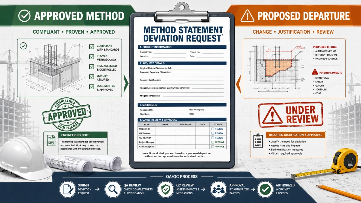
For example: if your specification requires a departure from a referenced standard, that departure must be documented and approved separately — this method statement will not capture that automatically. Always verify against your applicable drawings, specifications, and regulatory requirements.
Method statement content
Scope
Work Included
- Supply, installation, and testing of horizontal structured cabling (Cat6 or Cat6A) from Telecommunications Rooms (TRs) to Work Area Outlets (WAOs).
- Coordination and use of approved containment (trays, baskets, conduits, trunking) including penetrations and firestopping.
- Termination at patch panels and outlets, patch panel dressing, cable management, and administration/labeling per TIA-606.
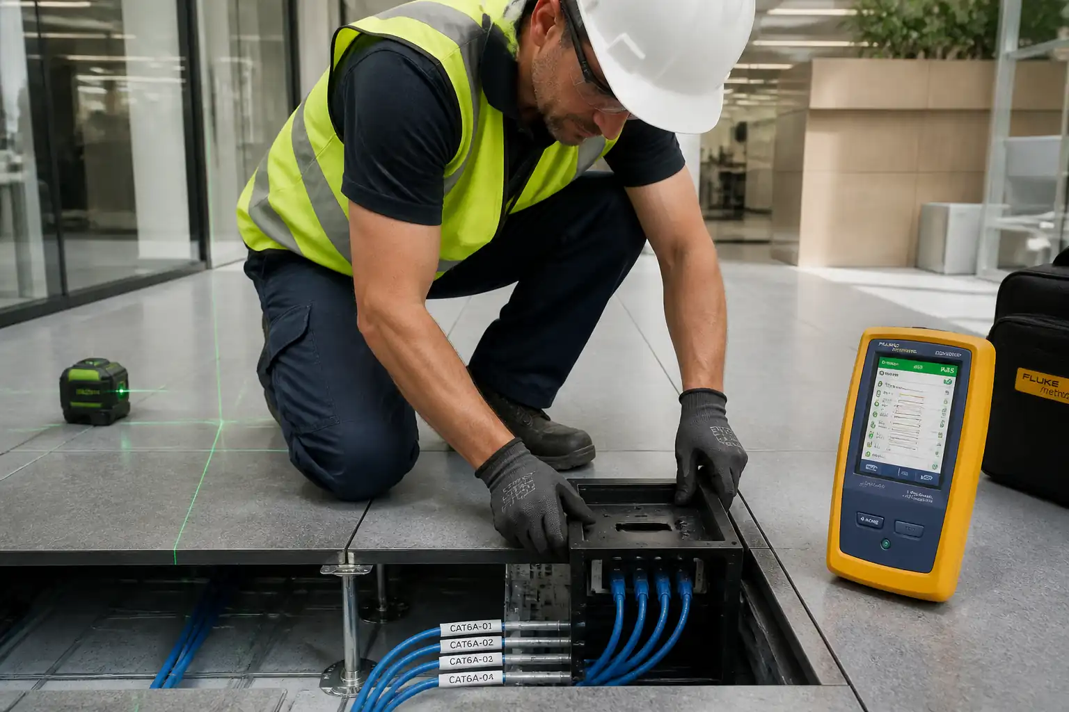
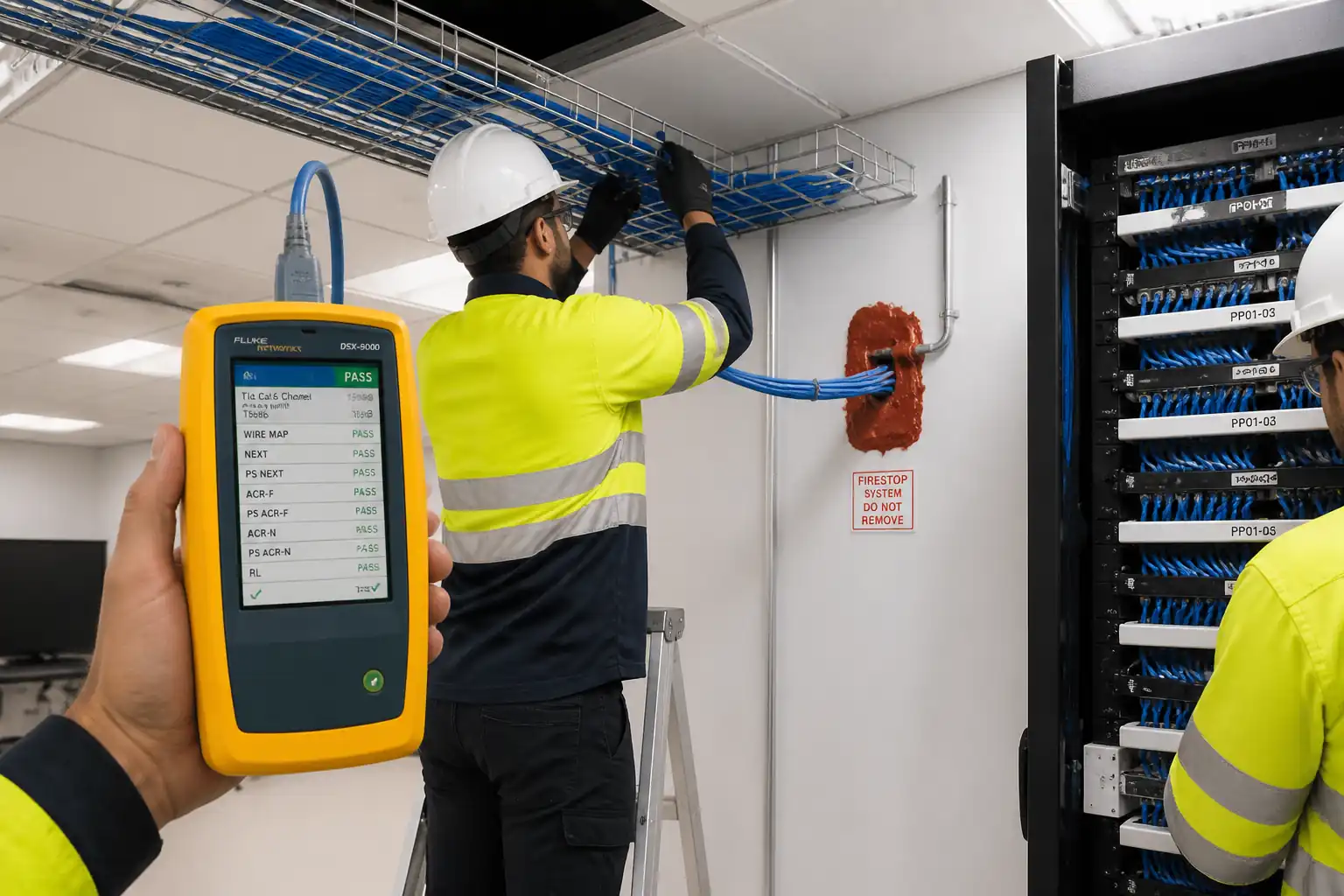
- Field certification testing with Fluke DSX series (or equivalent) to ANSI/TIA-568.2-D limits (Permanent Link or Channel as specified).
- Submission of test certificates, redlines/as-built drawings, labeling schedules, and O&M manuals.
Exclusions
- Active network equipment configuration and power works except as required for testing environments.
- Backbone/fiber infrastructure unless identified elsewhere.
- Containment installation by others (unless explicitly included). Coordination and compliance are included.
Interfaces
- Architectural ceilings/partitions; MEP containment; electrical power; firestopping contractor; IT/ELV integrator; main contractor scheduling and permits.
References
| Document Type | Reference / Number | Revision | Notes |
|---|---|---|---|
| Standard | ISO/IEC 11801-1: Information technology — Generic cabling for customer premises | Overall structured cabling performance and topology [Verify per project] | |
| Standard | ANSI/TIA-568.2-D: Balanced Twisted-Pair Telecommunication Cabling and Components | Categories, performance, termination, and field testing limits (Cat6/Cat6A) | |
| Standard | ANSI/TIA-569-D: Telecommunications Pathways and Spaces | Conduit/basket/tray fill, bend radii, clearances, separations [Verify per project] | |
| Standard | ANSI/TIA-606-C: Administration Standard for ICT Infrastructure | Labeling scheme, records, color coding, identifiers | |
| Standard | ANSI/TIA-607-D: Generic Telecommunications Bonding and Grounding (Earthing) for Customer Premises | Bonding of metallic pathways, racks, and cable trays | |
| Standard | ANSI/TIA-1152-A: Requirements for Field Test Instruments and Measurements for Balanced Twisted-Pair Cabling | Tester accuracy level (Level IIIe for Cat6, Level 2G for Cat6A) | |
| Standard | IEEE 802.3 (incl. 802.3af/at/bt) | PoE/PoE+/4PPoE considerations and bundle heating [Verify per project] | |
| Standard | IEC 60332-1/3, IEC 60754-2, IEC 61034-2 or CPR EN 50575 | Flame propagation, halogen/acid gas, smoke density; CPR Euroclass where applicable [Verify] | |
| Standard | UL 1479 / ASTM E814 or EN 1366-3 | Through-penetration firestop systems and approvals [Verify per region] | |
| Code | NEC (NFPA 70) or IEC 60364 series [Verify per jurisdiction] | Low-voltage comms circuits, separation from power, earthing |
Responsibilities
| Role | Responsibility | Name / Party |
|---|---|---|
| Project Manager | Project Manager | Contractor |
| Lead Engineer | ICT Lead Engineer | Contractor |
| Site Engineer | Site Engineer / Supervisor | Contractor |
| QA/QC Engineer | QA/QC Engineer | Contractor |
| HSE | HSE Manager/Officer | Contractor |
| Technicians | Structured Cabling Technicians | Contractor/Subcontractor |
| Consultant | Client/Consultant Representative | Client/Consultant |
Resources
| Resource Type | Description | Quantity | Remarks |
|---|---|---|---|
| Personnel | PM, ICT Lead, QA/QC, HSE | 4-6 | |
| Personnel | Supervisor, 6–12 technicians, 1 storekeeper | 8–14 | |
| Personnel | Certified field test operator for Fluke DSX | 1–2 |
Materials
| Material | Specification / Grade | Quantity | Remarks |
|---|---|---|---|
| Data cable | AWG23/24 solid, color per project [Verify] | As per BOQ | |
| Patch panel | Cat6/Cat6A, shielded as required | ||
| Keystone jacks & plates | Cat6/Cat6A rated | ||
| Patch cords | Cat6/Cat6A, lengths per layout | ||
| Labels | UV/abrasion resistant | ||
| Firestop | Rated to partition FRL [Verify] | ||
| Accessories | Non-metallic edge protection where required |
Equipment
| Equipment | Capacity / Type | Quantity | Inspection Required |
|---|---|---|---|
| Fluke DSX | 1–2 | ||
| Pulling tools | As required | ||
| Termination kit | Set per crew | ||
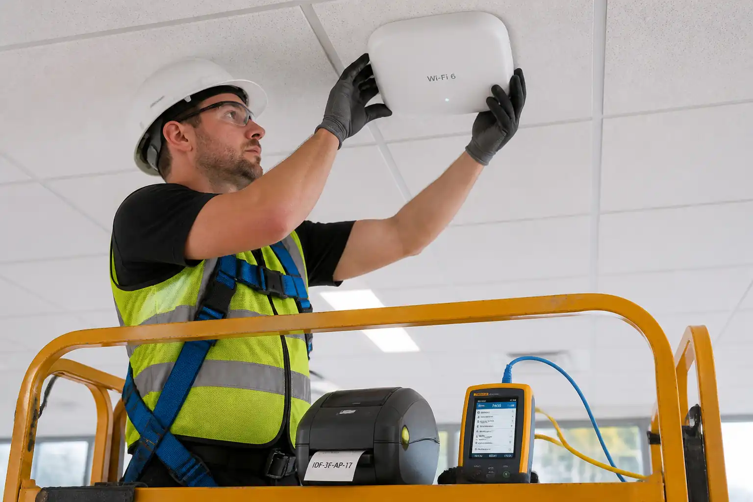
| Work at height | As required | ||
| Label printer | 1–2 | ||
| Cleaning | As required |
Prerequisites
- Approved IFC drawings, cabling layouts, TR elevations, schematics, schedules, and labeling matrix.
- Approved material submittals (cables, jacks, patch panels, firestop systems, labels) and MIRs.
- Confirm containment is installed, cleaned, free of burrs/sharp edges, earthed (if metallic), and load-rated; supports at required spacing [Verify per project; typical basket support ≤1.2 m centers].
- Confirm separation from power/EMI sources per TIA-569-D and local codes [typical: 50–100 mm in segregated metallic pathways, 300 mm in open pathways; [Verify per project specifications]].
- Penetration approvals and firestop system details available; opening sizes verified.
- Permits to Work: work-at-height, hot works (if drilling), ceiling access, out-of-hours work where required [Verify per project HSE plan and local regulations].
- Tester calibration certificates valid (<12 months). Termination tools and torque settings verified.
- RFI closures on clashes with MEP/architectural works; room access handover by Main Contractor; environmental conditions within 0–50°C and <85% RH non-condensing for cable handling [Verify].
- Coordination meeting completed; install sequence and areas released; method statement and ITP approved.
- Utility isolation/identification in ceiling voids; existing services visually inspected and protected.
Method Sequence
| Step | Activity | Description | Responsibility | Inspection / Hold Point |
|---|---|---|---|---|
| 1 | Material receiving and storage | Receive cables on intact drums, verify model/Category, jacket rating, length; store upright on pallets in dry indoor area (5–40°C). | Storekeeper / QA/QC | Visual, MIR |
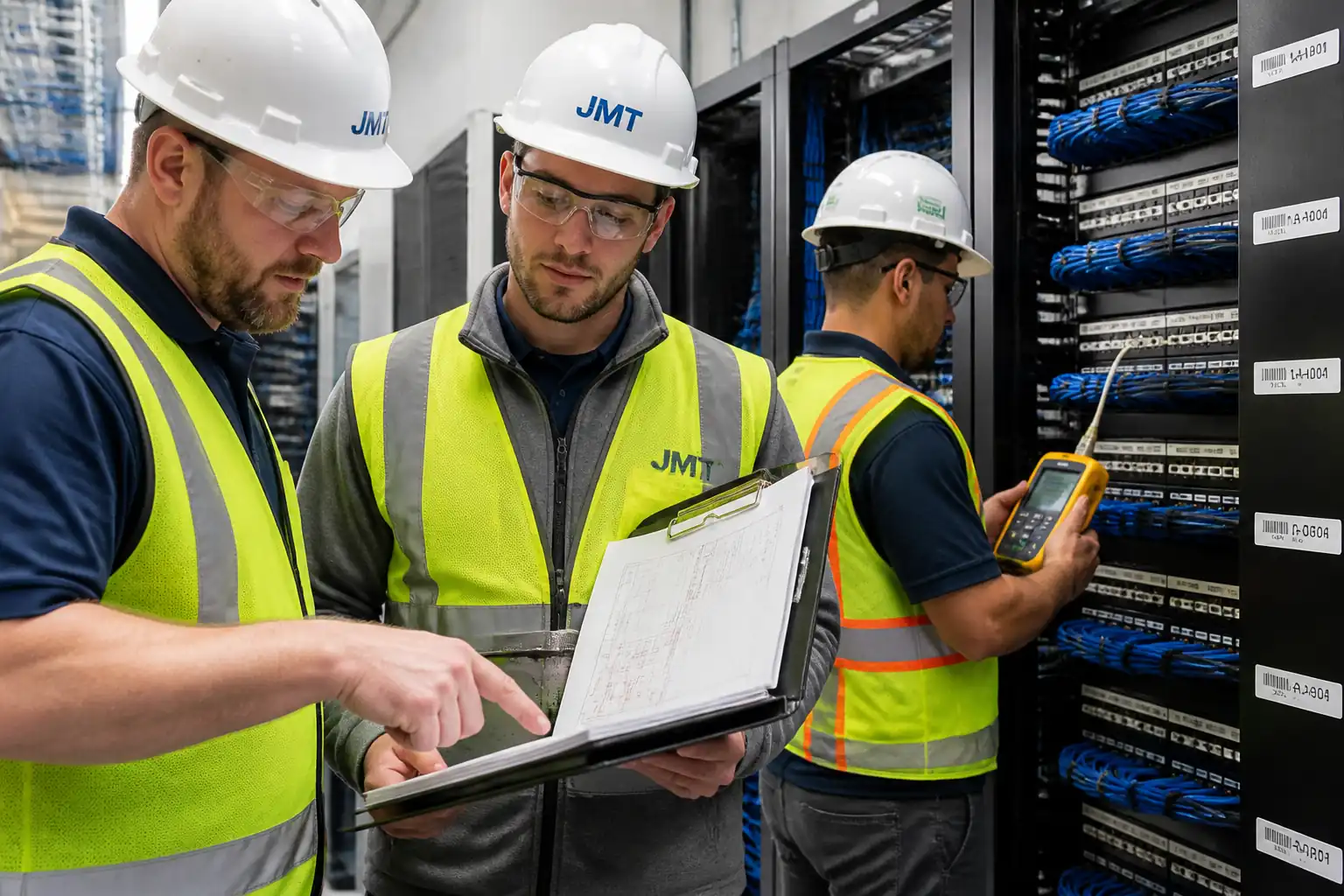
| 2 | Pre-install walkdown | Joint survey with MC/MEP to confirm routes, clearances, tray occupancy, penetrations, and TR readiness. | Site Engineer | Walkdown checklist |
| 3 | Containment preparation | Install grommets/bushings; deburr; clean trays; verify bonding of metallic pathways per TIA-607-D. | Supervisor | Visual |
| 4 | Cable pulling setup | Stage drums on jacks with pay-off in pulling direction; set rollers; insert draw wire; apply approved lubricant if needed; install pull rope rated >2× expected load. | Lead Technician | Toolbox talk; equipment check |
| 5 | Cable pulling – horizontals | Pull steady, keep bend radius ≥4×OD (UTP) or ≥8×OD (F/UTP); do not exceed max tensile 110 N (25 lbf) unless manufacturer states otherwise; bundle size and pathway fill per TIA-569-D. | Technicians | Monitor tension, radii |
| 6 | WAO termination | Leave 300 mm service loop at outlet; terminate to keystone per vendor tool; maintain pair untwist ≤13 mm for Cat6 and ≤6 mm for Cat6A; pinout 568A or 568B consistently project-wide. | Technicians | Visual, continuity spot-check |
| 7 | TR end preparation | Dress cables to patch panels with rear bars; leave ≥1 m slack neatly managed; install cables in numerical order as per schedule; maintain bend radius and separation from power. | Technicians | Visual |
| 8 | Patch panel termination | Terminate to patch panels per vendor instructions; torque hardware to spec; shield continuity verified for F/UTP; bond panel to rack earth bar per TIA-607-D. | Lead Technician | Continuity check |
| 9 | Labeling and administration | Apply labels at TR, intermediate points (if required), and outlet; identifiers per TIA-606-C: Floor–TR–Rack–Panel–Port ↔ Room–Outlet–Port; update cable schedule in real time. | Technicians / QA | Label audit |
| 10 | Firestopping of penetrations | Install approved firestop systems matching tested assembly; document system ID and quantity; apply backers as required. | Certified Firestop Installer | Inspection of system |
| 11 | Field certification testing | Set tester to Permanent Link (if testing links) or Channel (if patch cords included); select Cat6/Cat6A limit; test 100% of runs including: wiremap, length (≤90 m PL; ≤100 m CH), IL, NEXT/PSNEXT, ACR-F/PSACR-F, RL, Prop Delay, Delay Skew. Ambient 0–40°C. | Certified Tester | Real-time review |
| 12 | Rectification and retest | Identify defects (excess untwist, poor terminations, damage); re-terminate/replace as needed; limit ≤2 reterminations per jack [Verify]. | Technicians | Re-test |
| 13 | Patch panel dressing finalization | Install horizontal/vertical managers; bundle with Velcro; apply panel IDs and port maps; install blanking panels where unused. | Technicians | Visual |
| 14 | As-built documentation | Update floor plans with actual routes and outlet IDs; update schedules; compile test results, warranties, and O&M manuals. | QA/QC / CAD | Document review |
| 15 | Final inspection and handover | Joint inspection with Client/Consultant; submit certificates and closeout documents; demonstrate labeling and record traceability. | Project Manager / ICT Lead | Final WIR |
Health, Safety, and Environment – Safety Controls
Task-specific Hazards and Controls
1) Work at height (ladders, podiums, lifts)
- Consequence: Falls causing serious injury.
- Engineering/procedural control: Use podium steps/mobile towers with guardrails for sustained work; ladder only for light, short-duration tasks; keep 3-point contact; secure ladder at top/bottom; segregate work zone below.
- PPE: Safety helmet, non-slip safety footwear, gloves.
- Collective measure: Edge protection/guardrails, toe boards, exclusion zones.
- Inspection/permit/supervision: Pre-use inspection of access equipment; Work-at-Height permit; competent operator for MEWP; supervision by Site Engineer. [Verify per project HSE plan and local regulations]
2) Ceiling void work and existing services
- Consequence: Electric shock, service damage, falling debris.
- Control: Visual inspection before penetration; use non-conductive fish rods; lockout/tagout where isolation is required; use cable locators where unknown services; never sit/step on ceiling tiles; use platforms.
- PPE: Safety glasses, helmet, gloves.
- Collective measure: Service mapping, covers for open ceiling grids, debris netting if required.
- Inspection/permit/supervision: Permit for ceiling access; supervisor sign-off; daily TBT.
3) Drilling/coring for penetrations (if within scope)
- Consequence: Utility strike, flying debris, dust inhalation, fire risk.
- Control: Scan walls/soffits (GPR/ferroscan) as required; approved method statement for hot works; use drill collars and vacuums; fit grommets/bushings; stop-work if resistance change felt.
- PPE: Safety glasses/face shield, hearing protection, gloves, dust mask (P2/P3 as required).
- Collective measure: Extraction/HEPA vacuum; barriers and signage.
- Inspection/permit/supervision: Hot Work/Permit to Drill; HSE monitoring.
4) Manual handling of cable drums
- Consequence: Strain, crush injuries.
- Control: Use drum jacks/trolleys; team lift for small drums; keep hands clear; chock drums.
- PPE: Safety footwear, gloves.
- Collective measure: Mechanical aids; clear travel paths.
- Inspection/permit/supervision: Equipment inspection; manual handling training.
5) Sharp edges and cuts from trays and tools
- Consequence: Lacerations.
- Control: Deburr and fit edge protectors; use correct tools; maintain housekeeping.
- PPE: Cut-resistant gloves, long sleeves.
- Collective measure: Tray end caps/grommets installed.
- Inspection/permit/supervision: Pre-install checklists.
6) Noise and vibration from power tools
- Consequence: Hearing damage.
- Control: Select low-noise tools; limit exposure; schedule noisy tasks off-hours.
- PPE: Hearing protection (earplugs/muffs).
- Collective measure: Barriers and signage.
- Inspection/permit/supervision: Noise monitoring if required.
7) Firestopping chemicals/adhesives
- Consequence: Skin/eye irritation, respiratory effects.
- Control: Review SDS; use in ventilated areas; avoid incompatible materials; follow cure times.
- PPE: Nitrile gloves, goggles, disposable coveralls if needed.
- Collective measure: Spill kits, eyewash stations.
- Inspection/permit/supervision: COSHH/chemical permit as applicable; SDS on site.
8) Working over occupied areas
- Consequence: Falling objects injuring occupants.
- Control: Work after-hours or zone off; tool lanyards; no open ceiling without protection.
- PPE: Helmet for all in zone.
- Collective measure: Physical barriers, signage, spotter.
- Inspection/permit/supervision: Permit and coordination with building management.
9) Electrical bonding/earthing (metal containment)
- Consequence: Electric shock, EMC issues.
- Control: Qualified electrician to install bonds; verify continuity to earth bar; use marked bonding jumpers.
- PPE: Electrical gloves as required, insulated tools.
- Collective measure: Lockable earth bars, labels.
- Inspection/permit/supervision: Electrical permit; test records filed.
10) PoE bundle heating (during commissioning)
- Consequence: Cable temperature rise, performance degradation.
- Control: Adhere to bundle size limits per manufacturer; ensure ventilation and avoid tight bundles.
- PPE: General PPE.
- Collective measure: Cable managers to avoid compression.
- Inspection/permit/supervision: Engineer review before enabling high-power PoE.
Environmental Controls
- Waste management: Segregate copper cable offcuts for recycling; dispose of jackets/packaging per local regulations; collect and return empty drums.
- Dust and debris: Use HEPA vacuums when drilling/working in ceiling voids; cover sensitive equipment/furniture; wet methods where feasible.
- Noise: Schedule noisy works out-of-hours; use low-noise core bits; maintain equipment to reduce noise.
- Chemical handling: Store firestop compounds in bunded trays; prevent spills; use drip mats; follow SDS disposal guidance.
- Energy and lighting: Use task lighting with LED; switch off idle equipment.
- Indoor air quality: Use low-VOC sealants where specified; ensure ventilation during curing; maintain clean TRs free of construction dust.
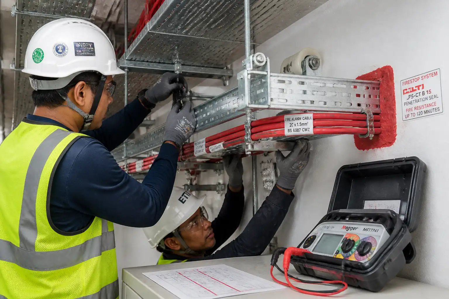
- Fire integrity: Seal all penetrations with approved systems immediately after cable installation; tag systems for traceability.
- Compliance: Follow project Environmental Management Plan and local environmental regulations [Verify per project HSE plan and local regulations].
Quality Assurance / Quality Control
Submittals
- Vendor datasheets and certificates of compliance for all passive components.
- Calibration certificates for field testers (<12 months).
- Labeling schema per ANSI/TIA-606-C including identifier format and color coding.
Controls and Tolerances
- Bend radius: ≥4×OD for U/UTP; ≥8×OD for F/UTP/shielded [Verify per cable vendor].
- Maximum pull tension: 110 N (25 lbf) typical unless manufacturer states otherwise [Verify].
- Conduit fill: ≤40% initial; basket/tray occupancy per TIA-569-D and manufacturer [Verify].
- Pair untwist at termination: ≤13 mm for Cat6; ≤6 mm recommended for Cat6A [Verify].
- Service loops: ≥300 mm at WAO; ≥1 m at rack end [Verify per project].
- Separation from power: Maintain per TIA-569-D/local code; typical 50–300 mm depending on pathway and power rating [Verify].
- Tester settings: Permanent Link for link certification unless Channel specified by Employer; ANSI/TIA-568.2-D limits; accuracy Level IIIe/2G as applicable.
Testing Frequency
- 100% of installed links tested and recorded.
- Spot continuity check after each panel/outlet termination batch (min. 10% sample or 5 links, whichever greater).
Records
- MIRs with batch numbers; WIRs at hold/witness points; daily site diaries; redline drawings; native tester files; PDF summaries; labeling registers; firestop logs; earthing continuity records.
Nonconformance
- Record NCR for any failed tests, damaged cables, or administration discrepancies; perform root cause analysis; corrective action and retest until PASS.
Training and Competence
- Termination and testing personnel certified/tooled per manufacturer; toolbox talks before cable pulling and before testing.
Attachments
- Cable schedule template and labeling matrix example (TIA-606 compliant).
- Typical TR rack elevation and patch panel dressing guide.
- Firestop system data sheets (UL/ETA) and installation instructions.
- Pre-pull checklist; termination checklist; test data naming convention guide.
- Sample WIR/MIR forms; daily report template.
- Manufacturer termination manuals and torque charts.
- Risk Assessment & Method Statement (RAMS) summary for this activity.
This content is a read-only public reference. Download or customize to get an editable version.
ITP preview
The first inspection activities from the linked ITP for Method Statement – Horizontal Data Cabling Installation (Office Floors):
| Activity | Inspection / Test | Acceptance Criteria | Responsibility | Record |
|---|---|---|---|---|
| Material delivery and MIR | Check cable drums, passive components, certificates | Materials match approved submittals; damage-free; certificates available | QA/QC Engineer / Consultant | MIR, photos |
| Pre-install walkdown (HP-1) | Verify routes, tray condition, fill limits, separations | Routes clear; separations achievable; trays bonded; supports per spec | Site Engineer / Consultant | Walkdown checklist, WIR approval |
| Containment preparation | Edge protection, bonding continuity, cleanliness | No sharp edges; earth continuity verified; area clean | Site Engineer / QA/QC | Inspection report |
Showing 3 of 11 inspection activities. View full ITP →
Related Inspection and Test Plan
An Inspection and Test Plan (ITP) is available for Method Statement – Horizontal Data Cabling Installation (Office Floors). The ITP defines the inspection activities, acceptance criteria, hold and witness points, responsible parties, and records required to verify the work described in this method statement.
View the Method Statement – Horizontal Data Cabling Installation (Office Floors) ITP →Frequently asked questions
Continue with related Quollnet resources connected to this method statement.