
Method Statement: Public Address & Voice Alarm (PAVA) System Installation, Configuration, Testing and Commissioning – Method Statement
AI-assisted method statement with matching ITP, PDF download, and Excel export.
More than a static template
Unlike a downloadable Word or PDF template, this method statement is an AI-assisted editable starting point connected directly to a matching Inspection and Test Plan. Every section is structured, project-adaptable, and ready to export.
- AI-assisted drafting — Customize every section with AI for your specific project scope.
- Linked ITP — A matching inspection and test plan is generated alongside the method statement.
- Multiple export formats — Download as a formatted PDF or editable Excel spreadsheet.
- Editable starting point, not a final document — Review, verify, and adjust all content against your project requirements before use.
Static template vs. Quollnet workflow
| Feature | Static template | Quollnet |
|---|---|---|
| Project-specific content | Manual fill-in required | AI-assisted customization |
| Linked ITP | Separate document, no link | Matching ITP included |
| Export formats | Usually PDF only | PDF and Excel |
| Structured sections | Free-form layout | 13 standardized sections |
| Saved to your account | Local file only | Cloud-saved, reusable |
| Content accuracy | You verify everything | AI-assisted, you still verify |
| Cost | Often free but time-intensive | Free to customize and download |
What you can customize
When you save this method statement to your account, every section becomes editable. The following 13 sections are included:
- Scope — Defines the activity and its boundaries.
- References — Standards, specifications, and drawings.
- Responsibilities — Roles and accountabilities.
- Resources — Labour, plant, and equipment summary.
- Materials — Materials and compliance requirements.
- Equipment — Tools and equipment details.
- Prerequisites — Hold points and pre-conditions.
- Method sequence — Step-by-step construction sequence.
- Safety controls — HSE risk controls and PPE.
- Environmental controls — Environmental mitigation measures.
- QA/QC — Quality inspection and test requirements.
- ITP — Inspection and Test Plan table (has its own page).
- Attachments — Referenced drawings and documentation.
Why this method statement is used
This method statement is used to define and communicate the approved procedure for carrying out method statement: public address & voice alarm (pava) system installation, configuration, testing and commissioning on site. It ensures the work is planned in advance, the correct resources and controls are in place, and all personnel understand responsibilities, sequence, quality requirements, and safety controls before work begins. It aligns site execution with the documented scope and acceptance expectations.
Who uses this method statement
This method statement is used by contractors, site supervisors, project engineers, QA/QC engineers, HSE officers, consultants, and client representatives. It serves as a shared reference for planning, execution, supervision, inspection, and approval of the activity on site.
When it is prepared and submitted
The method statement is prepared before the work activity starts and submitted as part of the pre-construction documentation package for review and approval.
Who reviews or approves it
The method statement is usually submitted to the client representative, consultant, resident engineer, or project management consultant for review and approval before the work commences.
Important approval note
This method statement is an AI-assisted editable starting point, not a pre-approved document. Before use on any project, all content must be reviewed and approved by the relevant parties (superintendent, principal contractor, or client representative) in accordance with your contract and project quality plan.
For example: if your specification requires a departure from a referenced standard, that departure must be documented and approved separately — this method statement will not capture that automatically. Always verify against your applicable drawings, specifications, and regulatory requirements.
Method statement content
Scope
Overview
This method covers supply, installation, configuration, testing, and commissioning of the Public Address & Voice Alarm (PAVA) system including:
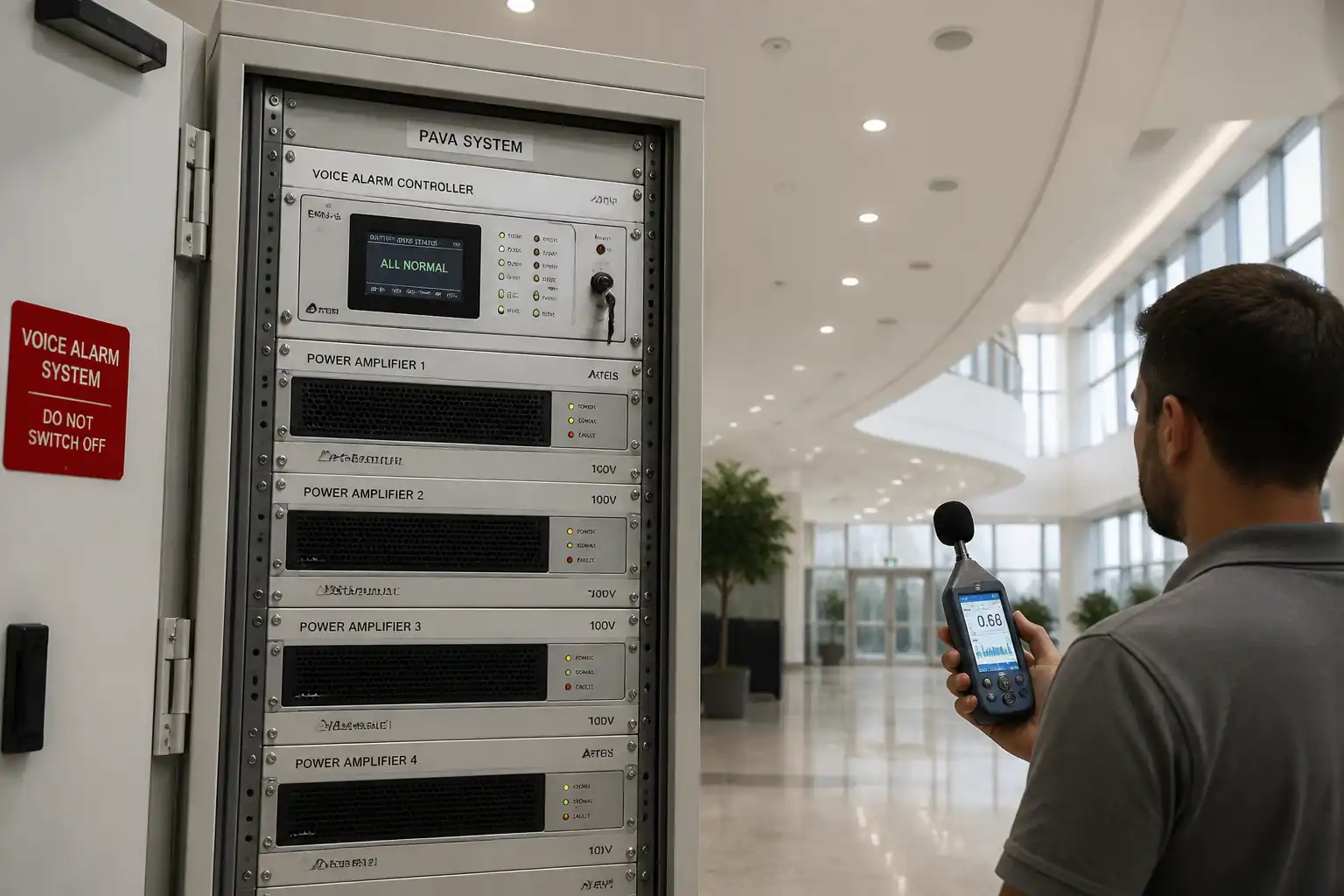
- 19" equipment rack assembly, EN 54-16 compliant control/indication equipment and router/DSP configuration
- Installation of 100 V line power amplifiers and backup/automatic changeover
- Supervised speaker circuits (EN 54-24 loudspeakers) including loop or radial topology, EOL/line monitoring modules, and line isolation where specified
- Structured cabling, terminations, labeling, and fire-stopping of penetrations
- Electrical power supplies, EN 54-4 power and VRLA batteries sizing and installation
- Functional tests: continuity, polarity, insulation resistance (prior to equipment connection), impedance/load, line supervision/fault annunciation, paging/priority logic, message playback, and battery autonomy
- Acoustic testing: background noise survey, SPL checks, equalization/levels, and STI/STIPA intelligibility measurements with reporting and corrective actions
Inclusions
- Matrix router/DSP programming (zones, priorities, ducking, EQ, limiters)
- Paging/emergency microphone setup and zone mapping
- Integration with Fire Detection & Alarm System (FDAS) for emergency control signals
- As-built documentation, training, and handover test packs
Exclusions
- FDAS supply/commissioning beyond dry contacts/interfaces
- Architectural works beyond necessary back-boxes/penetrations
- Network backbone outside the PAVA VLAN unless specified
[Verify per project specifications]
References
| Document Type | Reference / Number | Revision | Notes |
|---|---|---|---|
| Standard | BS 5839-8 | ||
| Standard | EN 54 series | Fault detection typically ≤100 s; PSU/battery sizing per duty cycle [Verify]. | |
| Standard | ISO 7240-19 / EN 50849 | ||
| Standard | IEC 60268-16 | ||
| Standard | IEC 62368-1, IEC 61000-6-x | ||
| Standard | BS 7671 or NFPA 70 | Apply regional code [Verify]. | |
| Standard | BS 7629-1 / BS 7846 | Cable category/PH rating per spec [Verify]. | |
| Project Docs | As approved | Follow manufacturer-specific line monitoring and configuration steps. |
Responsibilities
| Role | Responsibility | Name / Party |
|---|---|---|
| PM | Main Contractor | MC |
| Engineer | Specialist Subcontractor | SSC |
| Cx Engineer | Specialist Subcontractor | SSC |
| HSE | Main Contractor | MC |
| QA/QC | Main Contractor | MC |
| Vendor Rep | Vendor | Vendor |
| Engineer | Employer/Engineer | Employer |
Resources
| Resource Type | Description | Quantity | Remarks |
|---|---|---|---|
| Manpower | Cable pulling, terminations, device mounting. | As scheduled | |
| Manpower | Power supplies, earthing/bonding. | 1–2 | |
| Manpower | DSP/router programming, STI. | 1–2 | |
| Manpower | High-level speaker installation. | As required |
Materials
| Material | Specification / Grade | Quantity | Remarks |
|---|---|---|---|
| Controller | EN 54-16 | As schedule | |
| Amplifier | ≥ rated load + 20–30% headroom [Verify] | Per load calc | |
| Speakers | EN 54-24 | As BOQ | |
| Cable | BS 7629-1 / BS 7846 / IEC 60332 | As drawings | |
| Module | Compatible with EN 54-16 | Per circuit | |
| Batteries/PSU | EN 54-4 | As calc | |
| Mic | EN 54-16 compatible | As drawings | |
| Accessories | IEC 60297 | As required |
Equipment
| Equipment | Capacity / Type | Quantity | Inspection Required |
|---|---|---|---|
| Laptop | 1+ | ||
| Impedance Meter | 1 | ||
| Megger | 1 | ||
| SLM/STIPA | 1 | ||
| Network Tester | 1 | ||
| MEWP | As required | ||
| Drills | As required | ||
| Printer | 1 |
Prerequisites
- Approved shop drawings, schematics, cable schedules, loudspeaker layout, zoning diagrams
- Approved material submittals (EN 54 compliance certificates, DoP, test reports)
- Room readiness: equipment room complete with HVAC, lighting, earthing bar, dedicated power circuits, rack space
- Incoming mains, UPS (if applicable), and earthing verified and energized with PTW/LOTO controls
- Conduits/trays installed, inspected, and fire-stopping method approved
- Network services provisioned for PAVA (dedicated VLAN/QoS if IP-based), IP scheme documented
- Interface details with FDAS and BMS agreed; cause-and-effect matrix approved
- Battery sizing calculation approved; batteries delivered, dated, and float-charged as per vendor
- Calibrated test equipment with valid certificates
- HSE: task-specific Risk Assessment/Method Statement (RAMS) approved; permits to work for work at height, drilling, live testing; asbestos survey for existing buildings [Verify per project HSE plan and local regulations]
- Stakeholder notification and schedules for acoustic testing at planned times to manage noise exposure
Method Sequence
| Step | Activity | Description | Responsibility | Inspection / Hold Point |
|---|---|---|---|---|
| 1 | Rack Preparation and Mounting | Install 19" racks; fit earth bars; verify level and anchorage; install blank panels and cable managers. | Site Supervisor | Visual, torque of anchors |
| 2 | Controller/Amplifier Installation | Mount EN 54-16 controller/router and amplifiers; maintain ventilation clearances; fit backup/auto changeover modules. | ELV Engineer | Visual, nameplate check |
| 3 | Power and Earthing | Install dedicated circuits, breakers, and earthing; connect EN 54-4 PSU and battery cabinet (not yet energizing loads). | Electrician | Continuity, polarity |
| 4 | Speaker Cable Installation | Pull fire-resistant cables on approved routes; maintain segregation from LV power per code; install supports at ≤300–400 mm for verticals and ≤1.2 m for horizontals [Verify]. | Technician | Route/segregation inspection |
| 5 | First-Fix Devices | Mount back-boxes, speaker cutouts, grilles; ensure clearances from sprinklers/architectural features. | Technician | Visual |
| 6 | Terminations and Polarity | Terminate speakers with crimped ferrules; maintain polarity (+/–) throughout; install EOL/monitoring modules at line ends per manufacturer. | Technician | Random inspection 10% |
| 7 | Pre-Connection Cable Tests (Dead Tests) | Before connecting to electronics: perform continuity, ring out, and insulation resistance tests on each circuit. | ELV Engineer | Witness by QA/QC |
| 8 | Connect Circuits to Amplifiers/Router | Connect speaker lines to supervised outputs; install fuses; configure pilot-tone or impedance monitoring as per vendor. | ELV Engineer | Visual, torque |
| 9 | System Power-Up and PSU/Battery Setup | Energize PSU; set float/boost per vendor; connect batteries; verify charge current and fault relays. | Vendor Rep/ELV | Voltage/current check |
| 10 | Router/DSP Configuration | Program zones, priorities, routing, emergency messages; configure EQ, limiters, delay; set network/IP if applicable. | Commissioning Engineer | Software config review |
| 11 | Speaker Circuit Impedance and Load Check | Measure each 100 V line with impedance meter; compare with design load; verify spare capacity/headroom. | Commissioning Engineer | Witness by QA/QC |
| 12 | Line Monitoring and Fault Simulation | Enable pilot-tone/impedance monitoring; simulate open, short, and earth faults; verify annunciation within required time. | Commissioning Engineer | Functional test |
| 13 | Paging Mics and End-User Controls | Test PTT mic, zone selection, chimes; verify pre-recorded messages and language packs. | Commissioning Engineer | Operational check |
| 14 | Background Noise Survey | Measure LAeq in representative occupied conditions or simulated; map per zone. | Acoustic/Commissioning | Cal check pre/post |
| 15 | SPL Setting and Equalization | Set amplifier gains and DSP EQ to achieve target SPL and frequency balance without distortion. | Commissioning Engineer | Listening tests + SLM |
| 16 | STI/STIPA Measurements | Measure STIPA at ear height in representative grid; more points in acoustically challenging areas. | Acoustic/Commissioning | Witness by Consultant |
| 17 | Battery Autonomy Test (Calculation/Prove) | Confirm capacity: standby (e.g., 24 h) + alarm (e.g., 30 min) duty; perform discharge test if specified. | Vendor/ELV | Voltage log |
| 18 | Integration and Cause-and-Effect | Test FDAS triggers; verify phased evacuation, all-call, and zone isolation per matrix. | Commissioning Engineer | End-to-end test |
| 19 | Training and Documentation | Provide operator training; hand over O&M, as-builts, test packs, backups. | ELV Lead | Attendance |
| 20 | Snag Rectification and Final Acceptance | Close outstanding NCRs/snags; conduct SAT. | PM/ELV | Final walkthrough |
Health, Safety and Environment (HSE) – Task-Specific Controls
Key Hazards and Controls
1) Working at height (speakers at ceilings/atria)
- Likely consequence: Fall leading to serious injury or fatality
- Engineering/procedural control: Use MEWP with guardrails; exclude ladders for sustained work; install edge protection; use approved anchor points for short-duration tasks
- Required PPE: Full-body harness with lanyard, hard hat with chin strap, safety footwear, gloves
- Collective preventive measure: MEWP with secondary guarding; barriered exclusion zone below
- Inspection/permit/supervision: Daily MEWP LOLER inspection tag; Work at Height PTW; licensed operator; spotter present [Verify per project HSE plan and local regulations]
2) Electrical energization and battery hazards
- Likely consequence: Electric shock, burns, arc, acid spill
- Engineering/procedural control: LOTO during installation; insulated tools; battery handling trolley; spill kit; correct polarity and fusing; remove jewelry
- Required PPE: Insulated gloves, eye protection/face shield for battery work, apron
- Collective preventive measure: Barriers and warning labels on live panels; insulated covers on terminals
- Inspection/permit/supervision: Electrical PTW; battery MSDS; inspection of cables, fuses; supervision by authorized person
3) Drilling/penetrations and silica dust
- Likely consequence: Respiratory harm, eye injury, hidden service strike
- Engineering/procedural control: Service scan/permit before drilling; use drill with M-class extraction; wet core where permitted; debris containment
- Required PPE: Dust mask (FFP3), goggles, gloves, hearing protection
- Collective preventive measure: Local exhaust ventilation; segregation screens
- Inspection/permit/supervision: Permit to Drill with utility drawings; check fire-stop approvals
4) Noise exposure during SPL/STI testing
- Likely consequence: Hearing damage to workers/occupants
- Engineering/procedural control: Schedule tests off-hours; limit test duration; post warnings and restrict access; monitor dB levels
- Required PPE: Hearing protection (ear defenders)
- Collective preventive measure: Area cordon and signage
- Inspection/permit/supervision: Test notification to facility; HSE officer to verify controls
5) Manual handling of racks/amplifiers/batteries
- Likely consequence: Musculoskeletal injury, crush injury
- Engineering/procedural control: Use team lift, dollies, battery carriers; plan lift path
- Required PPE: Gloves, safety shoes
- Collective preventive measure: Mechanical aids; lift training
- Inspection/permit/supervision: Manual handling assessment; supervisor oversight
6) Fire integrity breaches
- Likely consequence: Compromised compartmentation and smoke spread
- Engineering/procedural control: Pre-approved fire-stopping system; certified installers; label all fire-stopped penetrations
- Required PPE: Standard PPE
- Collective preventive measure: Fire-stop registers and inspections
- Inspection/permit/supervision: QA fire-stop inspection and sign-off
7) Interface with Fire Alarm (false evacuation risk)
- Likely consequence: Unwanted evacuation/panic
- Engineering/procedural control: Coordinate isolation/disablement under PTW; temporary covers on call points; inform security/occupants; simulate signals safely
- Required PPE: Standard PPE
- Collective preventive measure: Lockable controls and signage
- Inspection/permit/supervision: FLS permit; witness by Consultant/Client
8) Asbestos/unknown materials in existing buildings
- Likely consequence: Exposure to hazardous fibers
- Engineering/procedural control: Review asbestos survey; no disturbance until cleared; licensed removal if found
- Required PPE: As specified by survey (e.g., P3 RPE)
- Collective preventive measure: Area isolation
- Inspection/permit/supervision: Permit; specialist supervision [Verify per local regulations]
Environmental Controls
- Noise: Schedule STI/SPL tests outside sensitive hours; maintain dB levels within local ordinance; notify neighbors where applicable
- Dust: Use on-tool extraction and wet methods; vacuum with M-class filters; clean daily
- Waste: Segregate cable offcuts, packaging, pallets; dispose batteries under hazardous waste/WEEE; maintain transfer notes
- Energy: De-energize non-essential equipment after hours; configure amplifiers for standby/sleep modes where supported
- Chemical: Store VRLA batteries upright in bunded area; maintain spill kits; train staff in spill response
- Fire-stopping: Use low-VOC mastics; maintain documentation for environmental compliance
- Transport: Optimize deliveries to reduce trips; use reusable crates where possible
[Verify per project environmental plan and local regulations]
Quality Assurance and Quality Control
QA/QC Strategy
- Submittal approvals: Verify EN 54 certificates, DoP, and compatibility matrices
- ITP adherence: Hold/witness points at dead testing, power-up, line monitoring, STI/STIPA
- Calibration: All meters (SLM/STIPA, impedance, IR) with in-date calibration; perform field acoustic calibrator checks pre/post
- Document control: Maintain cable schedules, amplifier load schedules, zone maps, DSP configuration backups, and cause-and-effect matrix
- Labeling: Permanent labels on racks, circuits, terminations, speakers; ferrules heat-shrink printed both ends
- Tolerances: Load within ±10% of design; headroom ≥20%; SPL within ±3 dB of target in coverage areas [Verify]
- Corrective actions: If STI below target, implement EQ, delay, level adjustments, speaker re-aim/additions, acoustic treatments (subject to client)
- As-builts: Redline drawings during works; issue CAD/PDF and native config files at handover
- Training: Operator and maintenance training with attendance sheets and quick guides
Attachments
- Approved equipment data sheets and EN 54 certificates (controllers, amplifiers, speakers, PSU)
- Cable schedules and amplifier load schedules
- Zoning diagrams and cause-and-effect matrix
- Shop drawings/as-built layouts with speaker locations and IDs
- Commissioning forms: dead tests, impedance, monitoring, SPL, STI/STIPA
- PSU/battery sizing calculation and records
- Configuration backups (router/DSP, messages, priorities) and passwords handover protocol
- Training agenda and attendance sheets
- Fire-stopping system approvals and registers
This content is a read-only public reference. Download or customize to get an editable version.
ITP preview
The first inspection activities from the linked ITP for Method Statement: Public Address & Voice Alarm (PAVA) System Installation, Configuration, Testing and Commissioning:
| Activity | Inspection / Test | Acceptance Criteria | Responsibility | Record |
|---|---|---|---|---|
| Materials receipt and certification | Check EN 54 certificates, DoP, serial numbers; visual for damage. | Compliant with approvals; no damage. | QA/QC + SSC | MIR/MTC, IRF |
| Cable routes and containment | Segregation from LV; support spacing; fire-stop provisions. | Per drawings/BS 7671; no sharp edges; correct tags. | QA/QC + Consultant | Inspection report with photos |
| Pre-connection dead tests | Continuity/ring-out; IR at 500 V DC cores-to-core/earth. | IR ≥ 1 MΩ; continuity consistent with loop length. | QA/QC (Witness) | Cable test sheets |
Showing 3 of 12 inspection activities. View full ITP →
Related Inspection and Test Plan
An Inspection and Test Plan (ITP) is available for Method Statement: Public Address & Voice Alarm (PAVA) System Installation, Configuration, Testing and Commissioning. The ITP defines the inspection activities, acceptance criteria, hold and witness points, responsible parties, and records required to verify the work described in this method statement.
View the Method Statement: Public Address & Voice Alarm (PAVA) System Installation, Configuration, Testing and Commissioning ITP →Frequently asked questions
Continue with related Quollnet resources connected to this method statement.