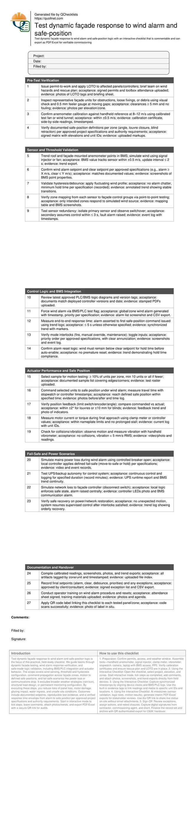
Test Dynamic Façade Wind Alarm and Safe-Position Logic
Definition: Test dynamic façade response to wind alarm and safe-position logic for commissioning and operations teams validating sensors, control logic, and actuators meet specification and reliably protect building envelopes during hazardous wind events.
- Proves wind sensor accuracy, thresholds, and debounce against specifications.
- Confirms control logic drives all façade zones to safe positions.
- Validates fail-safe behaviors during power or network interruptions.
- Interactive, commentable, export, QR code for field verification.
Test dynamic façade response to wind alarm and safe-position logic is the focus of this practical, field-ready checklist. We guide teams through dynamic facade testing, wind alarm response verification, and safe-mode logic validation, including BMS/PLC integration and actuator behavior. The scope covers wind sensing, threshold and hysteresis configuration, command propagation across façade zones, motion to defined safe positions, and fail-safe scenarios like power loss or communications drop. It excludes broader weather strategies (rain/sun), structural load design, or permanent monitoring configuration. By executing these steps, you reduce risks of panel loss, motor damage, glazing impact, water ingress, and unsafe site conditions. Outcomes include documented setpoints, reproducible test evidence, and a verified response time envelope from alarm to safe position per approved project specifications and authority requirements. Start in interactive mode to tick steps, leave comments, attach photos/trends, and export PDF/Excel with a secure QR link for audits.
- This checklist validates wind sensor accuracy, threshold settings, hysteresis, and zone mapping, then confirms BMS/PLC logic reliably commands all dynamic façade elements to defined safe positions within specified time and torque/current limits.
- It addresses real risk scenarios—sudden gusts, oscillating wind speeds, power or network failures—ensuring façades fail safe, alarms are time-stamped, and recoveries are controlled, preventing damage to cladding, motors, and glazing while protecting public safety.
- Interactive online checklist with tick, comment, and export features secured by QR code.
- Deliverables include calibrated readings, screenshots, trend logs, position-feedback reports, exception lists, and approvals—creating a traceable record that supports operations readiness, warranty claims, and compliance with approved project specifications and authority requirements.
Pre-Test Verification
Sensor and Threshold Validation
Control Logic and BMS Integration
Actuator Performance and Safe Position
Fail-Safe and Power Scenarios
Documentation and Handover
Why wind alarm logic must be proven under real conditions
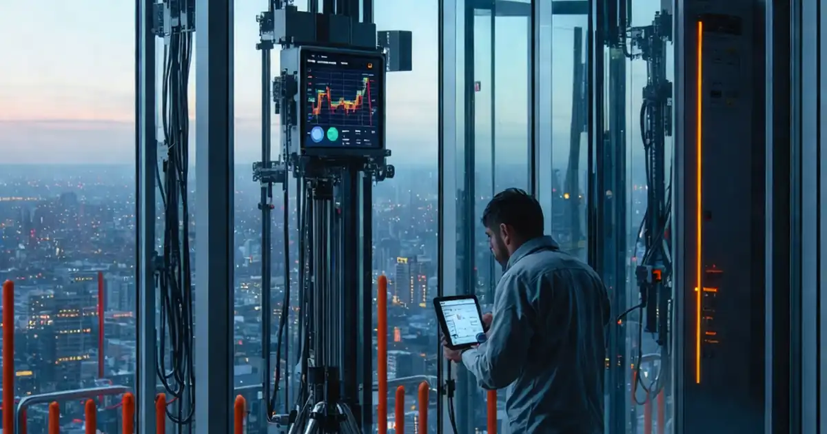
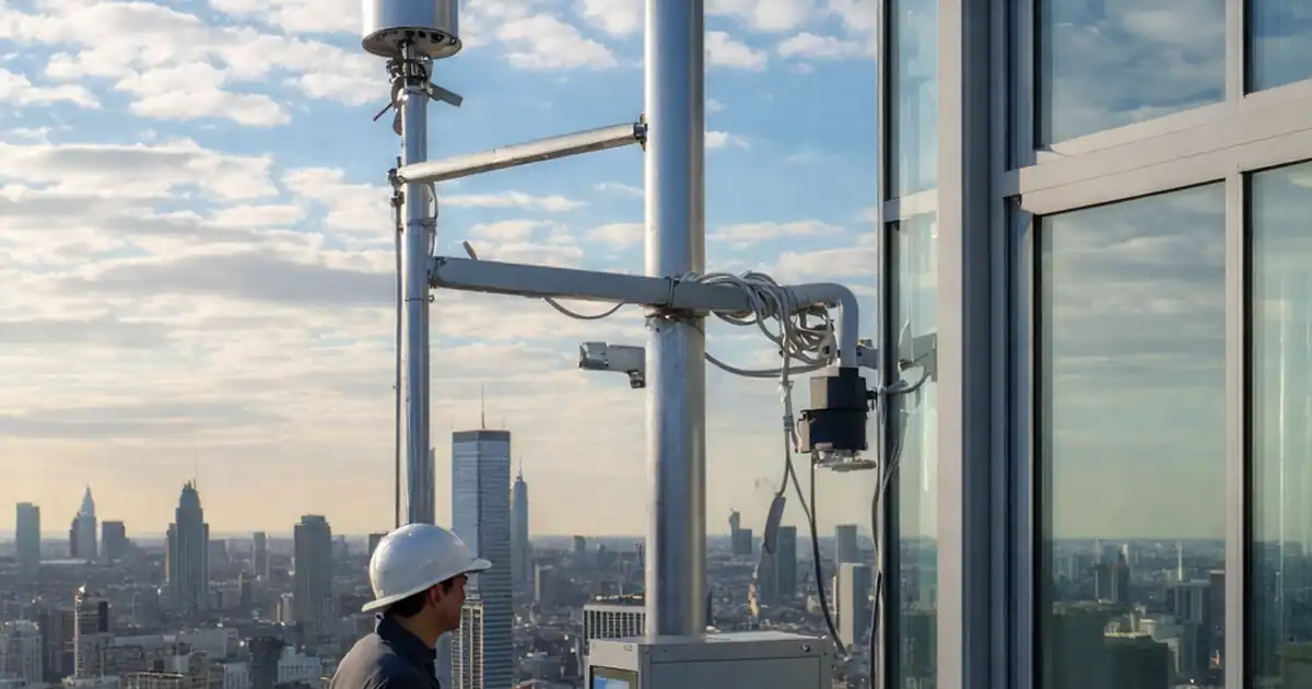
Dynamic façades reduce solar gain and glare but can become hazardous under high winds. Proving wind alarm logic ensures sensors read accurately, alarms trigger once, and commands propagate quickly to drive units into safe positions. In practice, gusting conditions can cause alarm chatter if hysteresis and debounce are not correctly configured, leading to excessive cycling and premature wear. Thorough testing captures response time, verifies priority interlocks (fire, maintenance, manual), and confirms BMS/PLC logic aligns with approved project specifications and authority requirements. Teams should trend data during simulated wind ramps, observing the exact moment alarms assert and clear. Jobsite examples show that a 1–2 s network delay or a mis-mapped zone can leave corner units exposed, where wind pressures are highest. This checklist builds a defensible record for warranty and handover, demonstrating that every tested unit reaches its defined safe position within the specified window and without overcurrent or vibration alarms.
- Trend alarms and commands with synchronized timestamps.
- Enforce hysteresis to prevent alarm chatter.
- Prioritize interlocks per approved specifications.
- Map sensors to zones with evidence screenshots.
Defining safe positions and acceptable motion performance
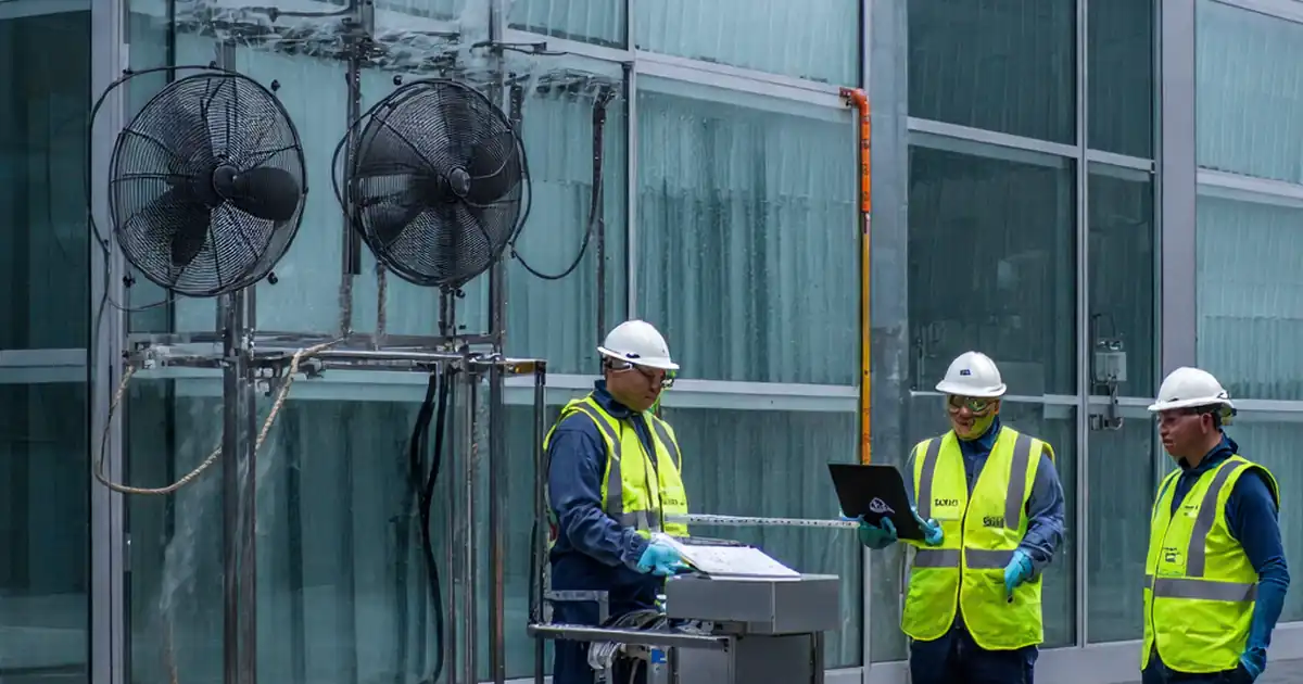
Safe positions must be explicitly defined by elevation and unit type: full closure for louvres, full retraction for blinds, or a specified angle minimizing wind load. Acceptance criteria should include travel time limits, end-stop verification, and allowable torque/current at approach. Feedback devices—limit switches or encoders—provide proof that commands translate to physical positions; align these with BMS points for transparent status. Use calibrated handheld meters and controller trends to validate current draw and timing. Field crews should sample a statistically meaningful set—at least 10% per zone, including edge and corner units that experience higher loads. Excessive vibration often indicates mounting issues or binding; a simple vibrometer reading in mm/s RMS provides objective evidence. Clear photographic records of before/after positions, with unit IDs visible, strengthen traceability. By combining these methods, teams can approve performance confidently and avoid latent defects that only emerge in the first wind event.
- Define safe positions per unit type and zone.
- Verify end-stops via feedback within tight tolerances.
- Time motion and compare to specified limits.
- Measure current/torque near end-stop.
Planning for fail-safe behavior and clean recovery
Real resilience depends on how the façade behaves when things go wrong. Power interruptions or network loss should not create unsafe movements or leave units exposed. Controllers must enforce a local, deterministic fail-safe, either holding or moving to the safe position as specified. UPS provisions should keep logic alive long enough to complete a safe action and log events. Recovery is equally important: after restoration, systems should not surge into motion; instead, they should verify interlocks, wind status below clear thresholds, and then resume supervised control. Logging the switchover, UPS runtime, and communication alarms creates an auditable trail. Testing redundancy—such as sensor failover—prevents blind spots during extreme weather. These steps prove that the building envelope remains protected and operators retain situational awareness through alarms and trends, reducing the risk of panel loss, glazing damage, or injuries during unexpected outages or gusts.
- Simulate power and network loss safely.
- Confirm local controller enforces safe state.
- Verify orderly recovery before resuming motion.
- Document UPS runtime and alarms.
How to Execute and Capture This Test
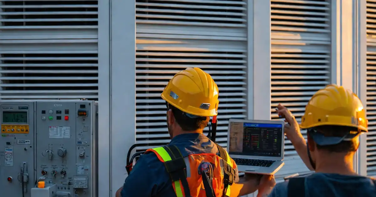
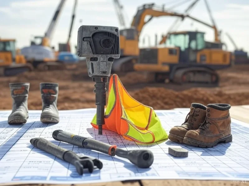
- Preparation: Confirm permits, access, and weather window. Assemble tools—handheld anemometer, signal injector, clamp meter, vibrometer, stopwatch, camera, laptop with BMS access, PPE. Verify calibration certificates and ensure rescue plan and LOTO are in place.
- Using the Interactive Checklist: Open the checklist, select project, elevation, and zones. Start interactive mode, tick steps as completed, add comments, and attach photos, screenshots, and trend exports directly from field devices.
- Using the Interactive Checklist: Capture synchronized timestamps by aligning device clocks and BMS/PLC logs. Use the built-in evidence tags to link readings and media to specific unit IDs and locations.
- Using the Interactive Checklist: At milestones (sensor validation, logic tests, motion results), generate interim PDF/Excel exports for stakeholder reviews. Use the QR link to share live status on-site without email attachments.
- Sign-Off: Review exceptions, assign actions, and retest closures. Capture digital signatures from contractor, commissioning agent, and client. Finalize the record set and archive with QR-authenticated export for O&M handover.
Call to Action
- Start Checklist Tick off tasks, leave comments on items or the whole form, and export your completed report to PDF or Excel—with a built-in QR code for authenticity.
- Download Excel - Dynamic Façade Wind Alarm and Safe-Position Test
- Download PDF - Dynamic Façade Wind Alarm and Safe-Position Test
- View Image - Dynamic Façade Wind Alarm and Safe-Position Test
Cite & Embed
“Dynamic Façade Wind Alarm and Safe-Position Test by Quollnet”
with a link to
this source page.

FAQ
Question: What wind speed should trigger the façade wind alarm?
Question: How many façade units should we test to validate performance?
Question: How do we simulate wind safely without exposing the site to hazards?
Question: What evidence should we keep for warranty and compliance?
Related Articles
Broader reading and guidance connected to this checklist topic.


Safety In Construction: The Role Of Periodic Safety Checklists

Related Checklists
Keep the workflow moving with nearby templates chosen from similar checklist content.