Dynamic Façade Actuator Synchronization Across Linked Panels
Definition: Test dynamic façade actuator synchronization across linked panels to verify coordinated motion, timing, and safety for commissioning teams, system integrators, and façade contractors on complex high-performance building envelopes.
- Confirm wiring, addressing, and control parameters before live testing.
- Measure position skew and timing jitter under load and wind signals.
- Validate safety interlocks, obstruction detection, and power-loss recovery.
- Interactive, commentable checklist; export PDF/Excel; QR code verification.
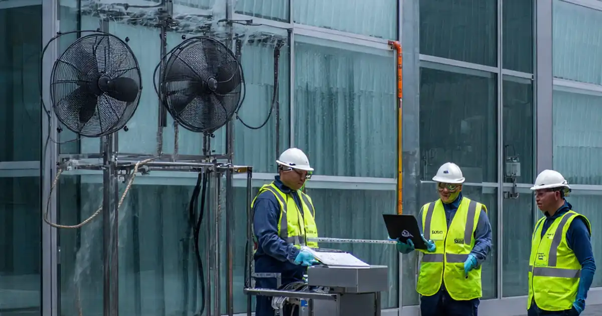
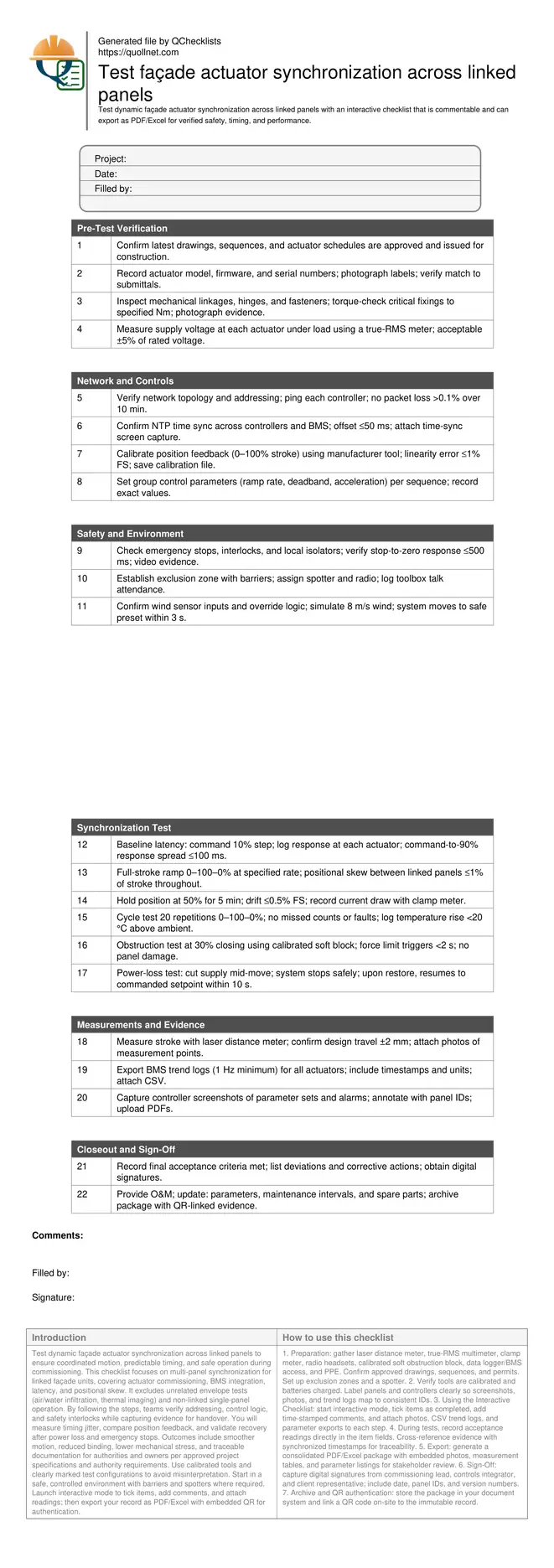
Test dynamic façade actuator synchronization across linked panels to ensure coordinated motion, predictable timing, and safe operation during commissioning. This checklist focuses on multi-panel synchronization for linked façade units, covering actuator commissioning, BMS integration, latency, and positional skew. It excludes unrelated envelope tests (air/water infiltration, thermal imaging) and non-linked single-panel operation. By following the steps, teams verify addressing, control logic, and safety interlocks while capturing evidence for handover. You will measure timing jitter, compare position feedback, and validate recovery after power loss and emergency stops. Outcomes include smoother motion, reduced binding, lower mechanical stress, and traceable documentation for authorities and owners per approved project specifications and authority requirements. Use calibrated tools and clearly marked test configurations to avoid misinterpretation. Start in a safe, controlled environment with barriers and spotters where required. Launch interactive mode to tick items, add comments, and attach readings; then export your record as PDF/Excel with embedded QR for authentication.
- Verify network addressing, time synchronization, and control parameters before movement to prevent panel skew, racking, and overload. The checklist guides you through evidence capture with photos, data logs, and signatures so issues are fixed before public exposure or warranty start.
- Run progressive motion tests across the full stroke, measuring timing jitter and positional skew under simulated wind and real loads. Acceptance thresholds focus on repeatable, safe, low-latency response while protecting linkages, hinges, and glazing from undue stress or binding.
- Interactive online checklist with tick, comment, and export features secured by QR code.
- Document safety interlocks, obstruction detection, and power-loss recovery to avoid unsafe states. Structured logging with synchronized clocks ensures traceability; final outputs include calibrated measurements, firmware versions, and approvals aligned with project specifications and stakeholder expectations.
Pre-Test Verification
Network and Controls
Safety and Environment
Synchronization Test
Measurements and Evidence
Closeout and Sign-Off
Why synchronization across linked panels matters
Linked façade panels must move as a coordinated set to prevent racking, hinge wear, and glazing stress. During commissioning, we verify that group commands yield uniform motion, with low latency and minimal positional skew. This checklist targets actuator networks, group controllers, and BMS interfaces that influence timing and feedback. It excludes weatherproofing, thermal, or acoustic testing to maintain scope discipline. Field experience shows most faults stem from misaddressed devices, unsynchronized clocks, and uncalibrated feedback. By establishing a clean baseline and measuring spread between actuators under realistic loads, teams detect binding and drift before handover. The acceptance cues focus on jitter, skew, drift, and safe recovery after interruptions. Evidence such as calibrated measurements, screenshots, and event logs supports closeout and warranty. Follow the steps in a controlled zone with a spotter, maintain communication, and document all settings before and after adjustments to ensure traceability and repeatability for future maintenance.
- Uniform motion reduces racking and hinge wear.
- Clock sync is essential for reliable log comparison.
- Calibration tightens feedback accuracy and repeatability.
- Evidence enables traceable, defensible handovers.
Measurement methods and acceptance criteria on site
Reliable synchronization testing blends simple tools with digital logging. Use laser distance meters to confirm stroke end-points and verify travel tolerances. Clamp meters track current draw to reveal binding, while thermography or onboard sensors show heat rise during cycling. Controller tools export parameter sets and trend logs, but only if clocks are synchronized. For timing, a data logger or BMS trending at 1 Hz or better allows calculation of response spread and jitter. Acceptance targets here prioritize safety and repeatability: skew within 1% of stroke during ramps, response spread within 100 ms on steps, drift below 0.5% at hold, and safe-stop within 500 ms for emergency signals. Record any deviations, apply corrective actions per approved project specifications and authority requirements, and retest with the same methods to confirm closure. Attach annotated photos marking measurement points so future technicians can reproduce the setup and validate ongoing performance during maintenance.
- Measure timing spread and jitter with synchronized logs.
- Target ≤1% skew across the full movement profile.
- Hold-position drift should remain under 0.5% FS.
- Emergency stops must achieve safe-stop within 500 ms.
- Retest after adjustments using identical methods.
Common field pitfalls and practical fixes
Commissioning teams often face issues like miswired polarity causing opposite motion, under-voltage at the end of long cable runs, or non-linear feedback because of incorrect scaling. Another frequent trap is parameter drift after firmware updates, which silently alters ramp rates or deadbands. Start by validating power under load, confirming address maps, and reapplying saved parameter sets. If skew persists, slow ramp rates and increase synchronization frequency to improve tracking, then retune once alignment is proven. Use obstruction tests with calibrated soft blocks to check force limits without risking damage. For power-loss scenarios, verify the resume logic lands on the correct setpoint, not just a safe park. Document each change, capture before/after logs, and seek sign-off only when targets are met under repeated cycles. This disciplined loop prevents latent faults reaching operations.
- Under-voltage causes slow or uneven travel.
- Firmware changes can reset parameters silently.
- Soft-block obstruction tests prevent damage.
- Slow ramps improve initial synchronization.
- Always compare before/after trends.
How to Use This Interactive Synchronization Test Checklist
- Preparation: gather laser distance meter, true-RMS multimeter, clamp meter, radio headsets, calibrated soft obstruction block, data logger/BMS access, and PPE. Confirm approved drawings, sequences, and permits. Set up exclusion zones and a spotter.
- Verify tools are calibrated and batteries charged. Label panels and controllers clearly so screenshots, photos, and trend logs map to consistent IDs.
- Using the Interactive Checklist: start interactive mode, tick items as completed, add time-stamped comments, and attach photos, CSV trend logs, and parameter exports to each step.
- During tests, record acceptance readings directly in the item fields. Cross-reference evidence with synchronized timestamps for traceability.
- Export: generate a consolidated PDF/Excel package with embedded photos, measurement tables, and parameter listings for stakeholder review.
- Sign-Off: capture digital signatures from commissioning lead, controls integrator, and client representative; include date, panel IDs, and version numbers.
- Archive and QR authentication: store the package in your document system and link a QR code on-site to the immutable record.
Call to Action
- Start Checklist Tick off tasks, leave comments on items or the whole form, and export your completed report to PDF or Excel—with a built-in QR code for authenticity.
- Download Excel - Dynamic Façade Actuator Synchronization Test
- Download PDF - Dynamic Façade Actuator Synchronization Test
- View Image - Dynamic Façade Actuator Synchronization Test
Cite & Embed
“Dynamic Façade Actuator Synchronization Test by Quollnet”
with a link to
this source page.
FAQ
Question: What are realistic acceptance criteria for synchronized linked façade panels?
Question: How do we measure timing spread without specialized high-speed tools?
Question: What common issues cause poor synchronization across linked panels?
Question: How should we test obstruction detection safely on glazed panels?
Related Articles
Broader reading and guidance connected to this checklist topic.


Related Checklists
Keep the workflow moving with nearby templates chosen from similar checklist content.