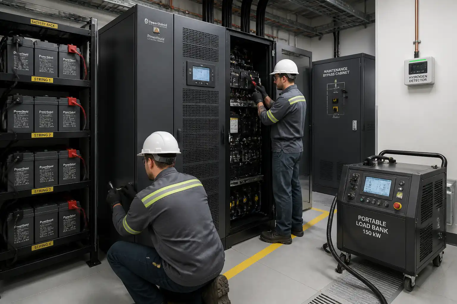

Method Statement: Installation and Commissioning of UPS System with Battery Racks, DC Cabling, Static & Maintenance Bypass, Ventilation, and Performance Tests – Method Statement
AI-assisted method statement with matching ITP, PDF download, and Excel export.
More than a static template
Unlike a downloadable Word or PDF template, this method statement is an AI-assisted editable starting point connected directly to a matching Inspection and Test Plan. Every section is structured, project-adaptable, and ready to export.
- AI-assisted drafting — Customize every section with AI for your specific project scope.
- Linked ITP — A matching inspection and test plan is generated alongside the method statement.
- Multiple export formats — Download as a formatted PDF or editable Excel spreadsheet.
- Editable starting point, not a final document — Review, verify, and adjust all content against your project requirements before use.
Static template vs. Quollnet workflow
| Feature | Static template | Quollnet |
|---|---|---|
| Project-specific content | Manual fill-in required | AI-assisted customization |
| Linked ITP | Separate document, no link | Matching ITP included |
| Export formats | Usually PDF only | PDF and Excel |
| Structured sections | Free-form layout | 13 standardized sections |
| Saved to your account | Local file only | Cloud-saved, reusable |
| Content accuracy | You verify everything | AI-assisted, you still verify |
| Cost | Often free but time-intensive | Free to customize and download |
What you can customize
When you save this method statement to your account, every section becomes editable. The following 13 sections are included:
- Scope — Defines the activity and its boundaries.
- References — Standards, specifications, and drawings.
- Responsibilities — Roles and accountabilities.
- Resources — Labour, plant, and equipment summary.
- Materials — Materials and compliance requirements.
- Equipment — Tools and equipment details.
- Prerequisites — Hold points and pre-conditions.
- Method sequence — Step-by-step construction sequence.
- Safety controls — HSE risk controls and PPE.
- Environmental controls — Environmental mitigation measures.
- QA/QC — Quality inspection and test requirements.
- ITP — Inspection and Test Plan table (has its own page).
- Attachments — Referenced drawings and documentation.
Why this method statement is used
This method statement is used to define and communicate the approved procedure for carrying out method statement: installation and commissioning of ups system with battery racks, dc cabling, static & maintenance bypass, ventilation, and performance tests on site. It ensures the work is planned in advance, the correct resources and controls are in place, and all personnel understand responsibilities, sequence, quality requirements, and safety controls before work begins. It aligns site execution with the documented scope and acceptance expectations.
Who uses this method statement
This method statement is used by contractors, site supervisors, project engineers, QA/QC engineers, HSE officers, consultants, and client representatives. It serves as a shared reference for planning, execution, supervision, inspection, and approval of the activity on site.
When it is prepared and submitted
The method statement is prepared before the work activity starts and submitted as part of the pre-construction documentation package for review and approval.
Who reviews or approves it
The method statement is usually submitted to the client representative, consultant, resident engineer, or project management consultant for review and approval before the work commences.
Important approval note
This method statement is an AI-assisted editable starting point, not a pre-approved document. Before use on any project, all content must be reviewed and approved by the relevant parties (superintendent, principal contractor, or client representative) in accordance with your contract and project quality plan.
For example: if your specification requires a departure from a referenced standard, that departure must be documented and approved separately — this method statement will not capture that automatically. Always verify against your applicable drawings, specifications, and regulatory requirements.
Method statement content
Scope
Overview
This method statement describes the end-to-end installation and commissioning of an Uninterruptible Power Supply (UPS) system, including:
- UPS cabinets/frames (rectifier/charger, inverter, static switch if integral)
- External static bypass switch (if separate) and maintenance bypass cabinet/board
- Battery racks and battery blocks/cells, inter-tier and inter-string connections
- DC cabling from battery strings to UPS DC bus, AC input/output cabling (interface scope as applicable)
- Earthing/bonding, labels/identification, protection devices
- Battery room ventilation and hydrogen detection (where lead-acid/NiCd batteries are used)
- Initial commissioning charge, baseline battery impedance test (HOLD), functional tests, and full-load backup discharge test (HOLD)
Inclusions
- Pre-installation verifications of room readiness, structural supports, clearances, HVAC and ventilation
- Mechanical installation, alignment, and anchorage
- Electrical installation, terminations, polarity/continuity checks
- Commissioning configuration, alarms/interlocks verification, and performance testing
- QA/QC documentation, redlines/as-builts, O&M handover
Exclusions
- Civil/architectural works outside the immediate equipment foundations/anchors
- Upstream utility works beyond defined points of connection
- Fire protection system installation (only interface checks included)
Assumptions
- Battery chemistry is VRLA lead-acid unless otherwise specified [Verify per project specifications]
- Room is purpose-built for electrical equipment with required fire rating and environmental control [Verify per project specifications]
- Outage/energization windows will be granted via approved Method of Procedure (MOP)
References
| Document Type | Reference / Number | Revision | Notes |
|---|---|---|---|
| IEC 62040-1/3 | |||
| IEC 60364 / BS 7671 / NEC | |||
| IEC 60896, IEC 62485-2, IEEE 484 | |||
| IEEE 1188 / 450 / 1106 | |||
| IEC 61439 / IEC 60947 | |||
| IEC 60228/60332/60754/61034/60529 | |||
| IEC 61238-1 | |||
| ISO 45001 / NFPA 70E | |||
| ISO / Local regs | |||
| Project Docs |
Responsibilities
| Role | Responsibility | Name / Party |
|---|---|---|
| Construction Manager | Construction Manager | Contractor |
| Electrical Supervisor | Electrical Supervisor | Contractor |
| QA/QC Engineer | QA/QC Engineer | Contractor |
| HSE Officer | HSE Officer | Contractor |
| Commissioning Engineer | UPS OEM Commissioning Engineer | Supplier/OEM |
| Battery Technician | Battery Specialist/Technician | Supplier/Subcontractor |
| Engineer/Client Rep | Engineer/Client Rep | Engineer/Client |
Resources
| Resource Type | Description | Quantity | Remarks |
|---|---|---|---|
| Skilled labor | UPS/battery installation and terminations | 4–8 [Verify per project] | |
| Skilled labor | Battery handling, rack positioning | 2–4 [Verify per project] | |
| Specialists | OEM and contractor commissioning activities | 2–3 (UPS OEM + Battery) | |
| HSE Officer | Worksite HSE supervision and permitting | 1 |
Materials
| Material | Specification / Grade | Quantity | Remarks |
|---|---|---|---|
| UPS Cabinets | Rated kVA/kW, input/output voltages, THDi, efficiency [Verify] | As per layout | |
| MBB | Rated to full UPS capacity [Verify] | 1 set | |
| Racks | Load rating per cell weight + factor [Verify] | As per design | |
| Batteries | Capacity (Ah), cells per string, terminals, venting [Verify] | As per strings | |
| Cables & lugs | Voltage drop ≤ 1–3% DC bus [Verify] | As per calc | |
| Ventilation system | Air changes ≥ 6 ACH typical [Verify] | As per calc | |
| Earthing | Earth resistance target ≤ 1–10 Ω [Verify] | As required |
Equipment
| Equipment | Capacity / Type | Quantity | Inspection Required |
|---|---|---|---|
| Torque wrench | 2–30 N·m (plus higher range for busbars) | 2–3 | Yes |
| Hand tools | Set | Yes | |
| Lifting aids | ≥ 100 kg per unit [Verify] | As required | Yes |
| Test instruments | Sets | Yes | |
| Impedance tester | 1 | Yes | |
| Load bank | Up to design kW | 1 | Yes |
| Power analyzer | 1 | No | |
| Ventilation test kit | 1 set | Yes |
Prerequisites
Approvals & Documentation
- Approved shop drawings, single-line diagrams (SLD), coordination drawings
- Approved submittals for UPS, batteries, racks, bypass cabinets, cables, ventilation, detectors
- Approved ITP, risk assessment, and Method of Procedure (MOP) for energization steps
- Permits to Work: Electrical, Hot Work (if any), Working at Height (if applicable) [Verify per project HSE plan and local regulations]
Site Readiness
- Battery/UPS room complete, clean, dry; ambient 20–25°C for VRLA [Verify spec range]
- Floor loading and plinths verified against equipment weight with safety factor [Verify]
- Anchorage inserts set-out and pull-out capacity verified [Verify]
- Clearances: front/rear/service access ≥ 1.0–1.2 m typical; aisle width ≥ 1.0 m; headroom ≥ 2.1 m [Verify]
- Earthing network installed and tested to target ≤ 1–10 Ω [Verify]
- Ventilation/HVAC operational; hydrogen detection installed but not yet energized for calibration
Materials & Tools
- All materials delivered, inspected (MIR), stored per OEM guidance; batteries within shelf-life; OCV checked and recorded
- Calibrated tools and meters available; torque charts and manufacturer terminal torque values accessible
- Insulated floor mats and spill kits (for wet/flooded systems) available
Interfaces
- Upstream AC input supply and downstream load panels identified; interlocks and EPO circuits defined
- Outage window and backfeed prevention plan agreed; lockout/tagout (LOTO) prepared
Briefings
- Pre-start coordination with OEM reps; toolbox talk covering electrical shock, arc-flash, chemical, and manual handling hazards
Method Sequence
| Step | Activity | Description | Responsibility | Inspection / Hold Point |
|---|---|---|---|---|
| 1 | Delivery and storage | Receive UPS, racks, batteries; inspect for damage, verify quantities, store batteries upright in cool, dry area; record OCV and date codes | Storekeeper/QAQC | MIR and Delivery Check |
| 2 | Room readiness verification | Check structural supports, clearances, earthing bar installed, ventilation functional; confirm permits | Electrical Supervisor | RFI/WIR |
| 3 | Setting out and anchors | Mark equipment footprint; drill and set anchors per layout; ensure edge distances and embedment | Site Engineer | Anchor inspection |
| 4 | Install racks | Assemble battery racks; level and plumb; fix to floor and, if required, wall/ceiling seismic bracing | Battery Tech | WIR |
| 5 | Place UPS cabinets | Position UPS and bypass cabinets; align; fix to floor; install anti-vibration pads if specified | Electrical Supervisor | WIR |
| 6 | Cable containment | Install cable tray/ladder, trunking, and supports; segregate AC, DC, and control per SLD | Electrical Team | WIR |
| 7 | Install DC/AC cables (un-terminated) | Cut to length; gland if required; pull cables to UPS, racks, MBB/SBS; identify polarity | Electrical Team | WIR |
| 8 | Terminations - UPS and MBB/SBS | Crimp lugs using calibrated tools; fit heat-shrink; torque per OEM; install barriers/covers | Electrical Team | WIR |
| 9 | Battery placement | Place cells/blocks on racks with correct orientation and spacing; install intercell connectors and insulators | Battery Tech | WIR |
| 10 | Battery string wiring | Connect series/parallel strings; install string fuses/breakers; route to DC bus with polarity markers | Battery Tech | WIR |
| 11 | Earthing and bonding | Bond UPS frames, racks, and doors; connect to main earth bar | Electrical Team | WIR |
| 12 | Ventilation and H2 detection commissioning (dry run) | Power and function test fans/dampers; verify interlocks to charger if specified; calibrate sensors | HVAC/Controls Tech | WIR |
| 13 | Pre-energization checks | Verify LOTO; confirm all covers, labels, and barriers in place; check battery interconnection polarity; confirm EPO and interlocks status | Electrical Supervisor | WIR |
| 14 | Initial energization and float charge | With OEM present, energize rectifier/charger; set float voltage and current; temperature compensation; observe stabilization | OEM Engineer | WIR |
| 15 | Baseline battery measurements (HOLD) | Measure and record each block voltage and impedance/internal resistance after stabilization period | Battery Tech/OEM | HOLD POINT - Client/Engineer Witness |
| 16 | Functional tests - inverter/static bypass | Test transfer to/from inverter and static bypass; simulate faults/overload per OEM limits | OEM Engineer | WIR |
| 17 | Maintenance bypass operation | Prove interlocks; transition load to MBB without backfeed; isolate UPS safely and restore | OEM/Contractor | WIR |
| 18 | Full-load backup discharge test (HOLD) | Apply load bank to rated kW; run from battery to end-voltage; monitor temperatures and voltages | OEM/Battery Tech | HOLD POINT - Client/Engineer Witness |
| 19 | Alarms, EPO, and monitoring integration | Verify remote alarms, SNMP/Modbus/BMS integration, EPO function (simulated if required) | Controls/Commissioning | WIR |
| 20 | Punch list clearance and handover | Close NCR/SNAG items; hand over as-builts, O&M manuals, spares; training | Contractor/OEM | Final inspection |
Safety Controls
Task-Specific Hazards and Controls
1) Electric shock and arc flash during energization
- Consequence: Severe injury, burns, fatality
- Engineering/procedural control: De-energized work preferred; LOTO with verified absence of voltage; insulated barriers and covers in place; arc flash study labels and boundaries applied; use insulated tools; follow approved MOP with step-by-step sign-off; restrict access
- Required PPE: Arc-rated clothing per incident energy [Verify], voltage-rated gloves (Class 0 or as required) with leather protectors, arc-rated face shield/hood, safety glasses, hearing protection, EH-rated footwear
- Collective preventive measure: Arc flash boundary marking, insulated mats, barriers
- Inspection/permit/supervision: Electrical Permit to Work; MOP approval; HSE and Supervisor presence; pre-use meter check on known source; tool calibration; [Verify per project HSE plan and local regulations]
2) Short circuit across battery terminals/links
- Consequence: Arc, burns, fire, battery damage
- Engineering/procedural control: Keep terminal covers on until connection; maintain correct polarity; use torque-limited insulated tools; remove metallic jewelry; install series fuses/breakers before string closure; use non-conductive mats; stage and handle one connection at a time with check-back calls
- PPE: Arc-rated gloves/gauntlets, face shield, safety glasses
- Collective: Insulated covers, physical separation of positive/negative tools, insulated mats
- Inspection/permit/supervision: Supervisor to verify polarity and sequence; QA/QC torque check log
3) Manual handling of heavy batteries and cabinets
- Consequence: Musculoskeletal injury, crush, foot injury
- Engineering/procedural control: Use mechanical aids (lift tables, pallet jacks); team lifts with weight limits; plan route; maintain neutral spine techniques; limit stack height
- PPE: Safety shoes with toe protection, gloves, back support as needed
- Collective: Trained riggers, spotters, clear walkways
- Inspection/permit/supervision: Lifting plan; equipment inspection tags current
4) Chemical exposure (lead-acid electrolyte)
- Consequence: Chemical burns, eye injury, environmental contamination
- Engineering/procedural control: Keep batteries upright; no smoking/open flames; provide spill kit and neutralizer; eyewash/shower within 10 m [Verify]; avoid overcharging; ventilation active
- PPE: Chemical-resistant gloves, goggles/face shield, apron (for flooded types); nitrile gloves for VRLA handling
- Collective: Secondary containment trays (if specified), absorbents
- Inspection/permit/supervision: COSHH/SDS available; HSE inspections
5) Hydrogen accumulation (lead-acid/NiCd)
- Consequence: Explosion risk
- Engineering/procedural control: Provide ventilation per calculation; interlock charger shutdown on high H2 if specified; install and calibrate H2 detectors; prohibit ignition sources; anti-static controls
- PPE: Standard electrical PPE
- Collective: Mechanical exhaust, gas detection system, intrinsically safe equipment where required
- Inspection/permit/supervision: Commission ventilation prior to charging; periodic detector bump tests
6) Working with load bank (heat and noise)
- Consequence: Burns, heat stress, hearing damage
- Engineering/procedural control: Position load bank with adequate clearance and exhaust; cord management; monitor ambient temperature; rotate staff; hydration plan
- PPE: Gloves, hearing protection if >85 dB(A)
- Collective: Barriers around hot surfaces; signage; fire extinguisher (CO2/dry powder)
- Inspection/permit/supervision: Temporary setup inspection; fire watch if required
7) Trip/fall hazards during installation
- Consequence: Injury from slips/trips
- Engineering/procedural control: Housekeeping; cable management; good lighting; marked access routes
- PPE: Safety footwear
- Collective: Barricades and caution tape
- Inspection/permit/supervision: Daily HSE walkdowns
8) Confined space/poor ventilation rooms
- Consequence: Hypoxia, exposure to gases
- Engineering/procedural control: Confirm not a confined space; if designated, follow confined space entry with gas monitoring and rescue plan
- PPE: As per permit
- Collective: Ventilation and monitoring
- Inspection/permit/supervision: Confined Space Permit if applicable [Verify]
9) Seismic anchoring/drilling
- Consequence: Striking embedded services, dust inhalation
- Engineering/procedural control: Scan floor for services; use dust extraction; verify embedment depth; use vacuum drills
- PPE: Dust mask (P2/P3), safety glasses, gloves
- Collective: Extraction/HEPA vacuums
- Inspection/permit/supervision: Permit to drill where required
Environmental Controls
Environmental Management
- Battery waste and packaging:
- Segregate pallets, plastics, and metals; recycle where possible
-
Used or defective batteries handled as hazardous waste; store in acid-resistant trays; manifest through licensed recycler [Verify local regulations]
-
Spill prevention and response:
-
Spill kits with neutralizer and absorbents at room entrance; immediate containment; notify HSE; contaminated materials disposed as hazardous waste
-
Ventilation and emissions:
-
Verify ventilation maintains H2 below alarm thresholds; no discharge of untreated fumes; ensure load bank exhaust does not affect adjacent intakes
-
Noise and heat from load bank:
-
Operate during allowed hours; use temporary acoustic screens if required; monitor temperatures to avoid HVAC overload
-
Dust and drilling debris:
-
Use vacuum extraction when drilling; collect and dispose per site procedures; no slurry discharge
-
Energy and commissioning efficiency:
-
Minimize unnecessary discharge/charge cycles; restore float promptly after tests
-
Documentation:
- Maintain waste transfer notes, calibration gas usage logs, and environmental inspection checklists
QA/QC
Quality Assurance and Control Plan
- Submittals and Approvals:
-
Verify all materials and drawings approved prior to installation; maintain latest revisions at site
-
Inspection and Test Records:
- 100% verification of polarity and torque on all battery terminals and busbars (record torque values)
- 100% continuity and IR test of DC/AC cables before connection to UPS electronics
-
100% check of labels, identification, and as-built routing
-
Measurements and Tolerances:
- Rack levelness ≤ 2 mm/m [Verify]; cabinet alignment within ±5 mm
- Cable minimum bend radius per cable OEM (typical ≥ 8D for copper) [Verify]
-
Earthing continuity R ≤ 0.1 Ω typical; overall earth resistance ≤ 1–10 Ω [Verify]
-
Battery Commissioning Metrics:
- Float voltage per cell at 25°C within OEM tolerance (e.g., 2.25–2.30 V/cell) [Verify]
- Temperature compensation applied per OEM (approx. −3 to −4 mV/°C/cell) [Verify]
-
Baseline impedance: no cell > 25–30% above string average/reference [Verify]
-
Functional Performance:
- Static bypass transfer time within OEM limits (e.g., ≤ 4 ms) [Verify]
-
Full-load autonomy ≥ specified minutes at rated load; end voltage within OEM limit [Verify]
-
Sampling and Frequency:
- Visual and mechanical checks: 100% of installed items
- Electrical tests: 100% of terminations and circuits in scope
-
Witness/Hold: Battery impedance test (HOLD), full-load backup test (HOLD)
-
Nonconformance and Corrective Action:
-
Document deviations; propose corrective actions; re-test affected scope; maintain NCR register
-
Handover Package:
- As-built drawings, settings sheets, torque logs, IR/continuity reports, battery baseline data, discharge test report, OEM commissioning certificates, training records
Attachments
Attachments and Appendices
- Approved shop drawings and SLDs
- UPS and battery OEM installation manuals and torque charts
- Ventilation and hydrogen detection calculations and datasheets
- Risk Assessment and Method of Procedure (MOP)
- Calibration certificates for torque wrenches, meters, detectors, load bank
- Checklists: Room Readiness, Rack Install, UPS Install, Pre-Energization, MBB Test
- Test templates: Cable IR/continuity, Earthing, Battery Baseline, Functional Tests, Discharge Test
- Training and handover forms
This content is a read-only public reference. Download or customize to get an editable version.
ITP preview
The first inspection activities from the linked ITP for Method Statement: Installation and Commissioning of UPS System with Battery Racks, DC Cabling, Static & Maintenance Bypass, Ventilation, and Performance Tests:
| Activity | Inspection / Test | Acceptance Criteria | Responsibility | Record |
|---|---|---|---|---|
| Material receipt - UPS, racks, batteries | Visual, quantity, OCV (batteries) | No damage; OCV within OEM limits; documents complete | QA/QC, Storekeeper | MIR, Delivery Report |
| Room readiness | Clearances, earthing, HVAC/ventilation | Per approved drawings/spec; earth ≤ 1–10 Ω [Verify] | Site Engineer, QA/QC | Room Readiness Checklist |
| Anchors and bases | Layout, level, torque/pull test (if required) | Level ≤ 2 mm/m; torque/pull per spec [Verify] | Site Engineer | Anchor Log |
Showing 3 of 19 inspection activities. View full ITP →
Related Inspection and Test Plan
An Inspection and Test Plan (ITP) is available for Method Statement: Installation and Commissioning of UPS System with Battery Racks, DC Cabling, Static & Maintenance Bypass, Ventilation, and Performance Tests. The ITP defines the inspection activities, acceptance criteria, hold and witness points, responsible parties, and records required to verify the work described in this method statement.
View the Method Statement: Installation and Commissioning of UPS System with Battery Racks, DC Cabling, Static & Maintenance Bypass, Ventilation, and Performance Tests ITP →Frequently asked questions
Continue with related Quollnet resources connected to this method statement.