
Method Statement – Security Command Centre Fit-Out and Commissioning – Method Statement
AI-assisted method statement with matching ITP, PDF download, and Excel export.
More than a static template
Unlike a downloadable Word or PDF template, this method statement is an AI-assisted editable starting point connected directly to a matching Inspection and Test Plan. Every section is structured, project-adaptable, and ready to export.
- AI-assisted drafting — Customize every section with AI for your specific project scope.
- Linked ITP — A matching inspection and test plan is generated alongside the method statement.
- Multiple export formats — Download as a formatted PDF or editable Excel spreadsheet.
- Editable starting point, not a final document — Review, verify, and adjust all content against your project requirements before use.
Static template vs. Quollnet workflow
| Feature | Static template | Quollnet |
|---|---|---|
| Project-specific content | Manual fill-in required | AI-assisted customization |
| Linked ITP | Separate document, no link | Matching ITP included |
| Export formats | Usually PDF only | PDF and Excel |
| Structured sections | Free-form layout | 13 standardized sections |
| Saved to your account | Local file only | Cloud-saved, reusable |
| Content accuracy | You verify everything | AI-assisted, you still verify |
| Cost | Often free but time-intensive | Free to customize and download |
What you can customize
When you save this method statement to your account, every section becomes editable. The following 13 sections are included:
- Scope — Defines the activity and its boundaries.
- References — Standards, specifications, and drawings.
- Responsibilities — Roles and accountabilities.
- Resources — Labour, plant, and equipment summary.
- Materials — Materials and compliance requirements.
- Equipment — Tools and equipment details.
- Prerequisites — Hold points and pre-conditions.
- Method sequence — Step-by-step construction sequence.
- Safety controls — HSE risk controls and PPE.
- Environmental controls — Environmental mitigation measures.
- QA/QC — Quality inspection and test requirements.
- ITP — Inspection and Test Plan table (has its own page).
- Attachments — Referenced drawings and documentation.
Why this method statement is used
This method statement is used to define and communicate the approved procedure for carrying out method statement – security command centre fit-out and commissioning on site. It ensures the work is planned in advance, the correct resources and controls are in place, and all personnel understand responsibilities, sequence, quality requirements, and safety controls before work begins. It aligns site execution with the documented scope and acceptance expectations.
Who uses this method statement
This method statement is used by contractors, site supervisors, project engineers, QA/QC engineers, HSE officers, consultants, and client representatives. It serves as a shared reference for planning, execution, supervision, inspection, and approval of the activity on site.
When it is prepared and submitted
The method statement is prepared before the work activity starts and submitted as part of the pre-construction documentation package for review and approval.
Who reviews or approves it
The method statement is usually submitted to the client representative, consultant, resident engineer, or project management consultant for review and approval before the work commences.
Important approval note
This method statement is an AI-assisted editable starting point, not a pre-approved document. Before use on any project, all content must be reviewed and approved by the relevant parties (superintendent, principal contractor, or client representative) in accordance with your contract and project quality plan.
For example: if your specification requires a departure from a referenced standard, that departure must be documented and approved separately — this method statement will not capture that automatically. Always verify against your applicable drawings, specifications, and regulatory requirements.
Method statement content
Scope
Overview
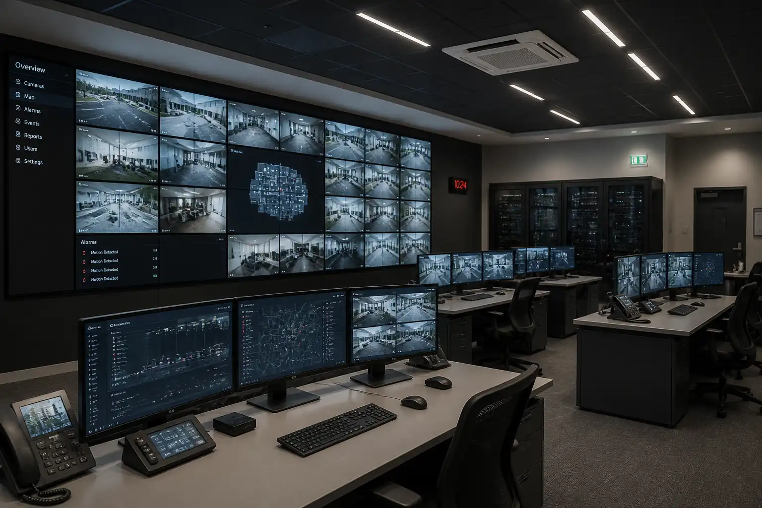
This Method Statement covers the end-to-end fit-out and commissioning of a Security Command Centre (SCC), including:
- Structural mounting and alignment of a modular video wall.
- Installation of operator console furniture and ergonomic adjustments.
- Equipment rack installation, power distribution units (PDUs), bonding/earthing.
- Cable containment and management (trays/ladder/underfloor raceways), cable pulling and terminations for power, structured cabling, AV, interconnects, and control.
- UPS installation and integration, including autonomy and transfer testing.
- Interface with environmental conditioning (HVAC/BMS) and control room lighting (ergonomic, low-glare, dimmable).
- Integration with structured cabling and AV systems.
- Verification of operator sightlines and ergonomics.
- Display calibration, audio and control integration, system endurance tests, and final commissioning.
Exclusions
- Base building civil works and major MEP infrastructure outside the room boundary.
- Core network/servers beyond demarcation points.
- Fire alarm system installation (except interface and coordination for penetrations and device relocations as needed).
Constraints and Assumptions
- Room is weather-tight and access-controlled.
- Permanent electrical supply available and pre-tested up to SCC DBs/UPS input.
- All architectural finishes substantially complete with low-reflectance coatings at video wall backdrop [Verify per project specifications].
- All manufacturer installation manuals and shop drawings approved prior to works.
References
| Document Type | Reference / Number | Revision | Notes |
|---|---|---|---|
| Standard | ISO 11064 (all parts) – Ergonomics of control centres | Layout, workstation design, environmental, displays, and evaluation. | |
| Standard | IEC 60364 – Low-voltage electrical installations (or NFPA 70/BS 7671 as applicable) [Verify per project] | Wiring, protection, earthing/bonding. | |
| Standard | IEC 62040 – UPS systems | UPS safety, performance, testing. | |
| Standard | ISO/IEC 11801 & ISO/IEC 14763-2/-3; TIA-568, TIA-569 | Structured cabling performance, installation, pathways, testing (copper/fiber). | |
| Standard | EIA-310 – Rack equipment mounting | Rack dimensions and mounting. | |
| Standard | EN 12464-1 / IES standards – Lighting of indoor work places | Illuminance, UGR, uniformity, glare control. | |
| Standard | ASHRAE (e.g., 55 for thermal comfort); Acoustic NR/NC criteria | Thermal comfort and background noise criteria for control rooms. | |
| Standard | IEC 61000 (EMC), IEC 60529 (IP ratings) | EMC compatibility and enclosure ingress ratings. | |
| Standard | EN 1366-3 / UL systems – Fire-stopping of service penetrations | Penetration seals and certification. | |
| Guideline | SMPTE/ITU-R BT.709 – Display/colorimetry; Manufacturer calibration specs | Video wall calibration targets (gamma, white point, luminance). | |
| Standard | ISO 9241-307 – Electronic visual display requirements (pixel defects) | Display pixel fault classes and inspection. |
Responsibilities
| Role | Responsibility | Name / Party |
|---|---|---|
| PM | Project Manager | Main Contractor |
| CM | Site Manager / Construction Manager | Main Contractor |
| MEP Supv. | MEP Supervisor | Main Contractor |
| AV Lead | AV Lead Engineer | Specialist Subcontractor |
| Cabling Lead | Structured Cabling Lead | Specialist Subcontractor |
| Cx Manager | Commissioning Manager | Main Contractor |
| HSE | HSE Manager / Officer | Main Contractor |
| QA/QC | Quality Engineer | Main Contractor |
| Client/Engineer | Client/Engineer Representative | Employer |
Resources
| Resource Type | Description | Quantity | Remarks |
|---|---|---|---|
| Personnel | 1 | ||
| Personnel | 1 | ||
| Personnel | 1 | ||
| Personnel | 1 | ||
| Personnel | 2–4 [Verify] | Adjust to project scale | |
| Personnel | 3–6 | Based on video wall size | |
| Personnel | 2–4 [Verify] |
Materials
| Material | Specification / Grade | Quantity | Remarks |
|---|---|---|---|
| Video wall displays | Resolution, pixel pitch, brightness ≥500 cd/m² [Verify] | As per layout | ISO 9241-307 pixel class per spec |
| Operator console furniture | ISO 11064-3 compliant; sit-stand 650–1250 mm [Verify] | As per layout | |
| Equipment racks | Static load rating ≥1000 kg [Verify] | e.g., 42U x 600/800W [Verify] | |
| Mounting anchors/fasteners | M10–M12 rated per design; torque per datasheet [Verify] | As calculated | |
| Copper data cables | Cat6A F/UTP or S/FTP, Class EA to ISO/IEC 11801 | As per BoQ | |
| Fiber optic cables | OM4/OS2 with LC connectors; IEC 61754 | As per BoQ | |
| UPS with batteries | IEC 62040; autonomy per load (e.g., 15–30 min) [Verify] | As per design | |
| Ergonomic lighting fixtures | EN 12464-1 compliant; UGR ≤19; CRI ≥80; 3000–4000K | As per layout | |
| Earthing/bonding bars and straps | IEC 60364-5-54; green/yellow 16–25 mm² [Verify] | As required |
Equipment
| Equipment | Capacity / Type | Quantity | Inspection Required |
|---|---|---|---|
| Vacuum lifter for displays | ≥100 kg | 1 | |
| Laser level | 1 | ||
| Torque wrench | 5–100 Nm | 2 | |
| Cable certifier | e.g., Fluke DSX-8000 or equivalent | 1 | |
| OTDR + light source/power meter | 1 | ||
| Colorimeter/spectroradiometer | ΔE and cd/m² capable | 1 | |
| Lux meter + UGR assessment tool | 1 | ||
| Micro-ohmmeter/continuity tester | 0–2 Ω | 1 | |
| Thermal imaging camera | 1 | ||
| MEWP/step-up platform | 1 |
Prerequisites
- Approved shop drawings, coordination drawings, and method statement/ITP.
- Verified room dimensions, substrate strength (concrete/steel wall) and as-built services scan (GPR/ferroscan as applicable) for mounting and cable routes.
- Permanent power available up to SCC DB/UPS input. Earth system tested and available.
- HVAC operational or temporary conditioning to maintain 20–24°C and 40–60% RH during installation and calibration [Verify per project specifications].
- Access/permits: Working at Height (WAH), Electrical Isolation/LOTO, Hot Works (if coring required), and delivery permits.
- Manufacturer installation manuals and lifting/handling instructions for video wall and UPS.
- Tools and test equipment with valid calibration certificates.
- Fire-stopping system approvals for planned penetrations.
- Room finishes: low-gloss paint behind video wall (low reflectance), glare control measures, acoustic finishes where specified.
- Pre-commissioning checklists prepared and approved.
Method Sequence
| Step | Activity | Description | Responsibility | Inspection / Hold Point |
|---|---|---|---|---|
| 1 | Site handover and verification | Joint inspection of room, verification of access, substrate condition, services locations, and dimensional checks against approved drawings. | CM / AV Lead / MEP Supv. | Inspection Request (IR) with photos and dimension log |
| 2 | Material receipt and storage | Offload using pallet jack/vacuum lifter; store displays vertically in crate; UPS/batteries stored per MSDS; humidity/temperature-controlled area. | CM / Storekeeper | Delivery inspection |
| 3 | Set-out and marking | Mark video wall datum lines, console positions, racks, and containment runs using laser level. Confirm sightline geometry with operator eye positions. | AV Lead / QA/QC | Hold point for set-out verification |
| 4 | Install cable containment | Install trays/ladder/underfloor ducts and grommets. Provide fire-stopping sleeves where required. Maintain separation between power and data (≥150 mm or divider) [Verify]. | MEP Supv. | IR for containment |
| 5 | Racks installation and bonding | Position racks per layout; anchor to floor if required; install rack earth bar and bond to main earth with labeled strap. | MEP Supv. | IR for rack placement |
| 6 | Video wall support/mount frame | Install mounting rails/frames and anchors as per manufacturer. Torque anchors to spec; verify substrate capacity. | AV Lead | Hold point for anchor inspection |
| 7 | Power rough-in and PDUs | Pull dedicated radial circuits to racks and video wall; install PDUs/RCBOs; identify circuits; ensure segregation from signal cables. | MEP Supv. | IR + testing |
| 8 | UPS installation | Place UPS and batteries; install input/output/bypass cabling; earthing; ventilation clearance maintained; firmware updates as required. | MEP Supv. / UPS Vendor | Vendor start-up witness |
| 9 | Structured cabling and AV cabling | Pull copper/fiber and AV signal cables via containment. Respect bend radius (Cu ≥4×OD; Fiber ≥10×OD static) and maximum pulls. | Cabling Lead / AV Lead | Progress inspections |
| 10 | Terminations and labeling | Terminate copper to keystones/patch panels; fiber to LC with proper polish/cleaning; apply permanent labels per scheme. | Cabling Lead | IR for terminations |
| 11 | Cable testing and certification | Test copper (Permanent Link) and fiber (LSPM + OTDR). Record results and remediate failures. | Cabling Lead / QA/QC | Witness testing |
| 12 | Lighting installation and aiming | Install ergonomic, dimmable lighting; set scenes to minimize screen glare; integrate with control if specified. | MEP Supv. / Lighting Vendor | IR + measurement |
| 13 | Console furniture installation | Assemble consoles; verify sit-stand operation and clearances; route cables via raceways; install task lighting/monitor arms. | AV Lead / Furniture Vendor | IR |
| 14 | Video wall panel mounting | Mount panels using OEM micro-adjust mounts; align for planar flatness and seam uniformity. | AV Lead | Hold point pre-power |
| 15 | Display calibration | Warm-up displays; calibrate luminance, white point (D65), gamma; verify uniformity and color difference. | AV Lead / QA/QC | Witness calibration |
| 16 | Sightline and ergonomics verification | Check operator eye-level vs display heights; verify viewing angles, character height/legibility; adjust mounts/console positions as needed. | AV Lead / Ergonomist / Client Rep | Witness check |
| 17 | Systems integration | Patch and configure AV, control processors, KVM, CCTV decoders, network, and audio. Implement presets and failover logic. | AV Lead / IT | Functional tests |
| 18 | UPS and power quality tests | Perform load/battery autonomy test and transfer to/from bypass; verify THD and thermal conditions in racks. | UPS Vendor / MEP Supv. / QA/QC | Witness |
| 19 | Environmental conditioning interface | Verify HVAC capacity, airflow, temperature and RH stability; check BMS/alarm interfaces. | MEP Supv. / Cx Manager | Measurement |
| 20 | Endurance and failover testing | Run continuous operation with typical sources; simulate failures (source/server link/UPS events) and verify recovery. | Cx Manager / AV Lead / Client Rep | SAT |
| 21 | Training and handover | Provide operator and maintenance training; submit O&M manuals, as-builts, warranties; snag rectification. | PM / AV Lead / MEP Supv. | Handover meeting |
Health, Safety, and Environment (HSE) – Safety Controls
Task-specific hazards and controls
1) Manual handling of displays/UPS
- Hazard: Musculoskeletal injury, crush/pinch.
- Consequence: Strains, fractures, dropped loads.
- Engineering/procedural control: Use vacuum lifters, trolleys; team lifts with clear commands; weight/CoG known; keep in crates until at install point.
- Required PPE: Safety shoes, cut-resistant gloves, back support as needed.
- Collective measure: Exclusion zone during lifts; banksman in place.
- Inspection/permit: Pre-use lifting equipment inspection; lifting plan/toolbox talk.
2) Working at height (video wall mounting/aiming)
- Hazard: Falls from step-ups/MEWP.
- Consequence: Serious injury/fatality.
- Control: Use suitable podium steps/MEWP with guardrails; maintain 3-point contact; do not overreach; secure tools with lanyards.
- PPE: Harness with lanyard if required by MEWP; hard hat with chin strap.
- Collective: Barricade work area; spotter.
- Inspection/permit: WAH permit; MEWP inspection tag; operator license [Verify per project HSE plan and local regulations].
3) Electrical works and UPS energization
- Hazard: Electric shock/arc flash.
- Consequence: Burns, cardiac arrest, fire.
- Control: LOTO; prove dead before work; use insulated tools; fit covers; vendor start-up for UPS; maintain creepage/clearances.
- PPE: Arc-rated clothing as required, insulated gloves, face shield for live testing within permitted scope.
- Collective: Barriers and signage during energization; dedicated test window.
- Inspection/permit: Electrical permit to work; calibrated test meters.
4) Anchor drilling into walls/floors
- Hazard: Striking concealed services; flying debris; silica dust.
- Consequence: Electrocution, flooding, eye injury, respiratory harm.
- Control: Services scan and permit; use drilling jigs with dust extraction; vacuum class M/H; stop if unexpected voids.
- PPE: Safety glasses, hearing protection, FFP2/3 mask.
- Collective: Spotter monitoring scan map; barriers.
- Inspection/permit: Penetration permit; anchor torque recorded; sample pull-tests witnessed.
5) Trip hazards from cabling and packaging
- Hazard: Slips/trips.
- Consequence: Minor to serious injury.
- Control: Maintain tidy work fronts; cable mats/ramps; immediate waste removal.
- PPE: Safety footwear.
- Collective: Clear walkways marked; daily 5S checks.
- Inspection/permit: Housekeeping inspections.
6) Battery handling (UPS)
- Hazard: Chemical exposure/thermal runaway.
- Consequence: Burns, fumes, fire.
- Control: OEM crates; no smoking/ignition sources; MSDS available; spill kit; trained personnel only.
- PPE: Chemical-resistant gloves, goggles, apron for electrolyte risks (VRLA minimal but consider).
- Collective: Ventilated area; emergency eyewash where required.
- Inspection/permit: Vendor supervision; COSHH assessment [Verify per project].
7) Noise and vibration from tools
- Hazard: Hearing damage.
- Consequence: Temporary/permanent hearing loss.
- Control: Low-noise tools; limit exposure time per HAVS policy.
- PPE: Hearing protection.
- Collective: Schedule noisy tasks off-hours.
- Inspection/permit: Noise monitoring if required.
8) Fire risk from hot works (if coring/cutting required)
- Hazard: Sparks/ignition of finishes.
- Consequence: Fire/smoke damage.
- Control: Hot work permit; fire watch; cover combustibles; extinguishers on hand.
- PPE: Flame-resistant gloves, goggles.
- Collective: Isolation of detectors or covers with approval.
- Inspection/permit: Hot work permit and fire watch logs.
Environmental Controls
- Waste electrical and electronic equipment (WEEE): Segregate displays, electronics, cabling offcuts, and batteries. Use licensed recyclers; retain transfer notes.
- Packaging waste: Returnable crates where possible; recycle cardboard/plastics; avoid polystyrene where feasible.
- Dust control: Use on-tool extraction and HEPA vacuums; damp wipe displays and consoles; protect HVAC intakes.
- Noise management: Limit drilling to permitted hours; use low-noise anchors; provide notice to occupants.
- Energy management: Use temporary LED task lighting; switch off equipment when not in use; enable display eco-modes post-calibration as allowed.
- Spill prevention: Secondary containment for batteries/UPS fluids; spill kits available; immediate cleanup and reporting.
- VOCs and air quality: Select low-VOC adhesives/paints; allow off-gassing before commissioning.
- Environmental monitoring: Log temperature/RH during calibration and endurance tests.
[Verify per project HSE plan and local regulations]
QA/QC Requirements
Controls and Records
- Submittals: OEM datasheets, shop drawings, wiring schematics, lighting calculations, anchor design, UPS method, test equipment calibration certificates.
- Inspections: IRs at each stage; hold/witness points for set-out, anchors, video wall alignment, calibration, UPS start-up, endurance test.
- Testing frequencies: 100% test of copper/fiber links; 100% display calibration; sample anchor pull-out tests (≥10% or min 3 per wall) [Verify per project specifications].
- Labeling: Per ISO/IEC 14763-2 scheme; heat-shrink or printed labels at both ends; racks and PDUs uniquely identified.
- Tolerances:
- Containment level ±5 mm/5 m; support spacing ≤1.5 m [Verify].
- Rack verticality ±2 mm/2 m; bonding ≤0.1 Ω to earth bar.
- Video wall flatness ±2 mm across array; seam uniformity ±0.3 mm [Verify].
- Lighting: 300–500 lux task; UGR ≤19; uniformity ≥0.6 [Verify per EN 12464-1].
- HVAC: 20–24°C; RH 40–60%; background noise NR/NC 30–35.
- Power tests per IEC 60364: continuity, insulation resistance (≥1 MΩ @ 500 VDC), polarity, EFLI, RCD trip tests where applicable.
- UPS tests per IEC 62040: autonomy test at 25–50% load; transfer to/from bypass; alarms/remote monitoring.
- Calibration: Target D65 6500K ±200K; gamma 2.2±0.1; luminance 120–160 cd/m² ±10%; ΔEavg ≤2 (max ≤3); uniformity ≤10%; pixel defects within ISO 9241-307 class as specified.
- Sightlines: Vertical ≤35°, horizontal ≤30°; minimum character height ≥ viewing distance/200; optimal viewing distance ≈ 1.2–2.5 × pixel pitch(mm) [Verify per OEM].
- Fire-stopping: Tested systems (EN 1366-3/UL); ID tags and as-builts recorded.
- Documentation: Certification reports (PDF + native files), calibration files, UPS logs, lighting survey, environmental logs, O&M manuals, warranties.
Attachments
- Approved shop drawings and coordination drawings (latest revision).
- Manufacturer installation manuals for video wall, mounts, racks, UPS, lighting.
- Lifting plan and WAH permits; electrical PTW/LOTO forms.
- Cable schedules and labeling scheme.
- Test equipment calibration certificates.
- Anchor design calculations and product ETA/ICC approvals.
- Fire-stopping system datasheets and approvals.
- Pre-commissioning checklists; IR templates.
- O&M manuals, spare parts lists, and warranties.
- Training materials and user guides.
This content is a read-only public reference. Download or customize to get an editable version.
ITP preview
The first inspection activities from the linked ITP for Method Statement – Security Command Centre Fit-Out and Commissioning:
| Activity | Inspection / Test | Acceptance Criteria | Responsibility | Record |
|---|---|---|---|---|
| Room and substrate verification | Dimensions, substrate integrity, services scan review | Room dims within tolerance; substrate sound; no clashes with services | CM / QA-QC | IR, survey report |
| Containment installation | Support spacing, level, bonding | Spacing ≤1.2–1.5 m [Verify]; level ±5 mm/5 m; bonding ≤0.1 Ω | MEP Supv. / QA-QC | IR, continuity record |
| Rack installation & bonding | Plumb and bonding test | Verticality ±2 mm/2 m; bonding ≤0.1 Ω to earth | MEP Supv. / QA-QC | IR, bonding test |
Showing 3 of 18 inspection activities. View full ITP →
Related Inspection and Test Plan
An Inspection and Test Plan (ITP) is available for Method Statement – Security Command Centre Fit-Out and Commissioning. The ITP defines the inspection activities, acceptance criteria, hold and witness points, responsible parties, and records required to verify the work described in this method statement.
View the Method Statement – Security Command Centre Fit-Out and Commissioning ITP →