
Method Statement: BMS Integration with Smoke Control Systems and Fire Alarm Interface – Method Statement
AI-assisted method statement with matching ITP, PDF download, and Excel export.
More than a static template
Unlike a downloadable Word or PDF template, this method statement is an AI-assisted editable starting point connected directly to a matching Inspection and Test Plan. Every section is structured, project-adaptable, and ready to export.
- AI-assisted drafting — Customize every section with AI for your specific project scope.
- Linked ITP — A matching inspection and test plan is generated alongside the method statement.
- Multiple export formats — Download as a formatted PDF or editable Excel spreadsheet.
- Editable starting point, not a final document — Review, verify, and adjust all content against your project requirements before use.
Static template vs. Quollnet workflow
| Feature | Static template | Quollnet |
|---|---|---|
| Project-specific content | Manual fill-in required | AI-assisted customization |
| Linked ITP | Separate document, no link | Matching ITP included |
| Export formats | Usually PDF only | PDF and Excel |
| Structured sections | Free-form layout | 13 standardized sections |
| Saved to your account | Local file only | Cloud-saved, reusable |
| Content accuracy | You verify everything | AI-assisted, you still verify |
| Cost | Often free but time-intensive | Free to customize and download |
What you can customize
When you save this method statement to your account, every section becomes editable. The following 13 sections are included:
- Scope — Defines the activity and its boundaries.
- References — Standards, specifications, and drawings.
- Responsibilities — Roles and accountabilities.
- Resources — Labour, plant, and equipment summary.
- Materials — Materials and compliance requirements.
- Equipment — Tools and equipment details.
- Prerequisites — Hold points and pre-conditions.
- Method sequence — Step-by-step construction sequence.
- Safety controls — HSE risk controls and PPE.
- Environmental controls — Environmental mitigation measures.
- QA/QC — Quality inspection and test requirements.
- ITP — Inspection and Test Plan table (has its own page).
- Attachments — Referenced drawings and documentation.
Why this method statement is used
This method statement is used to define and communicate the approved procedure for carrying out method statement: bms integration with smoke control systems and fire alarm interface on site. It ensures the work is planned in advance, the correct resources and controls are in place, and all personnel understand responsibilities, sequence, quality requirements, and safety controls before work begins. It aligns site execution with the documented scope and acceptance expectations.
Who uses this method statement
This method statement is used by contractors, site supervisors, project engineers, QA/QC engineers, HSE officers, consultants, and client representatives. It serves as a shared reference for planning, execution, supervision, inspection, and approval of the activity on site.
When it is prepared and submitted
The method statement is prepared before the work activity starts and submitted as part of the pre-construction documentation package for review and approval.
Who reviews or approves it
The method statement is usually submitted to the client representative, consultant, resident engineer, or project management consultant for review and approval before the work commences.
Important approval note
This method statement is an AI-assisted editable starting point, not a pre-approved document. Before use on any project, all content must be reviewed and approved by the relevant parties (superintendent, principal contractor, or client representative) in accordance with your contract and project quality plan.
For example: if your specification requires a departure from a referenced standard, that departure must be documented and approved separately — this method statement will not capture that automatically. Always verify against your applicable drawings, specifications, and regulatory requirements.
Method statement content
Scope
Overview
This method statement covers the complete integration, commissioning, and testing of the Building Management System (BMS) with life-safety smoke control systems, including:
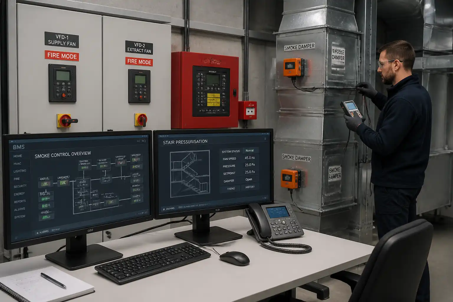
- Interface to smoke control fans (exhaust/supply/pressurization), motorized smoke/fire dampers, differential pressure/airflow sensors, fan/VFD fire mode signals, and status feedback.
- Fire mode sequence coordination per the approved Fire Strategy and Cause & Effect Matrix.
- Hardwired and/or BACnet/Modbus interfaces to the Fire Alarm & Detection System (FAS/FACP) and any dedicated Firefighter’s Smoke Control Panel (FSCP) where provided.
- Pre-functional checks, point-to-point testing, device calibration, cause & effect testing by scenario/zone, integrated system testing (IST), witnessed functional testing, quality records, and final acceptance documentation.
Inclusions
- Verification of installation, labeling, cable types/segregation, and panel terminations.
- Configuration of BMS controllers, networks (BACnet/IP, MS/TP, Modbus RTU/TCP as applicable), and life-safety priority handling.
- Calibration of differential pressure sensors and airflow measurement devices.
- Commissioning of smoke control fans with VFD fire override, damper actuation and end-switch feedback, status monitoring, and alarm handling.
- Trending, alarm thresholds, response time verification, and performance reporting.
- Training of end-user/FM team and handover of O&M, as-built, and QA/QC records.
Exclusions
- Base building structural works, permanent power installation, and base fire alarm system supply/installation (by others).
- Smoke performance modeling or CFD (design activity), unless specifically instructed.
Constraints & Interfaces
- Life-safety systems shall not be inhibited or impaired without approved permit and method (temporary impairments managed under Permit-to-Work). Priority of fire commands must override any BMS commands. [Verify per project HSE plan and local regulations]
References
| Document Type | Reference / Number | Revision | Notes |
|---|---|---|---|
| Standard | NFPA 92; EN 12101-3/6/8 | [Verify per project specifications] | |
| Standard | NFPA 72; BS EN 54-2; UL 864 (if applicable) | Life-safety interface precedence. | |
| Standard | ISO 16484-2/3/5; ASHRAE 135 | ||
| Standard | IEC 60364; IEC 60331; BS 7629-1/BS 7846 | [Verify per local code/NFPA 70-NEC where applicable]. | |
| Standard | ISO/IEC 17025 | ||
| Project Docs | Latest approved revisions | Contract drawings/specifications prevail. |
Responsibilities
| Role | Responsibility | Name / Party |
|---|---|---|
| PM | Main Contractor | Main Contractor |
| Commissioning Manager | Main Contractor/Commissioning Specialist | Commissioning Specialist |
| BMS Engineer | BMS Vendor/Integrator | BMS Vendor |
| FA Engineer | FAS Vendor | FAS Vendor |
| Supervisor | Electrical Subcontractor | Electrical Subcontractor |
| OEM Rep | OEMs | VFD/Damper/Fan OEM |
| HSE Manager | Main Contractor | Main Contractor |
| QA/QC | Main Contractor | Main Contractor |
| Consultant/AHJ | Engineer/AHJ | Engineer/AHJ |
| FM | Client/Operator | Client/Operator |
Resources
| Resource Type | Description | Quantity | Remarks |
|---|---|---|---|
| Human | Controls programming, commissioning, graphics, and testing. | 2–4 [Verify per project size] | |
| Human | Loop checks, sensor calibration, functional testing. | 3–6 [Verify per project size] | |
| Human | Terminations, rectifications, labeling. | 3–8 [Verify per project size] | |
| Human | On-site HSE supervision during live tests. | 1 |
Materials
| Material | Specification / Grade | Quantity | Remarks |
|---|---|---|---|
| Power/Control Cables | Cable type per spec | ||
| I/O Modules | |||
| Sensors | 0–250 Pa (typical) [Verify] | ||
| CTs/DPS | |||
| Dampers | |||
| VFD |
Equipment
| Equipment | Capacity / Type | Quantity | Inspection Required |
|---|---|---|---|
| PC | 2 | ||
| DMM/Calibrator | 2 sets | ||
| Pressure meter | 2 | ||
| 1 each | |||
| As required | |||
| Per person | |||
| 1 set/crew |
Prerequisites
- Approved shop drawings, I/O schedules, network architecture, cause & effect matrix, Fire Strategy, and panel schematics.
- Permanent power available to relevant panels, VFDs, and controllers; earth bonding verified.
- Cable installation complete: segregation per code; fire-rated where required; labeling consistent with point lists.
- FAT for BMS panels (if applicable) and OEM start-up reports available for VFDs/fans/dampers.
- Calibration certificates for instruments (ISO/IEC 17025 traceable) available and in date.
- Network addressing plan (BACnet/Modbus), time sync (NTP) source identified; BMS server/backups prepared.
- Permits: electrical work permit, fire system impairment/notification plan, hot work (if any), access/working at height. [Verify per project HSE plan and local regulations]
- Stakeholder notifications issued (building occupants, security, AHJ/Consultant) with test schedule.
- Emergency stops and local/remote selectors checked for correct position and labeling.
- FAS/FSCP logic and priorities agreed; clear demarcation that life-safety commands override BMS outputs at all times.
Method Sequence
| Step | Activity | Description | Responsibility | Inspection / Hold Point |
|---|---|---|---|---|
| 1 | Field Verification & Readiness | Verify installation quality: cable types/segregation, terminations torque-checked, labeling, enclosure IP/fire rating, earthing, and controller panel integrity. | Electrical Supervisor, QA/QC | Visual and checklist |
| 2 | Power-Up & Communication | Energize controllers/VFDs; verify BACnet/Modbus addressing, routing, and time sync; confirm no critical alarms. | BMS Integrator | Online check |
| 3 | Point-to-Point I/O Loop Checks | Stimulate each input/output from field to BMS and back; verify scaling, polarity, end-device labeling, and alarms. | BMS Integrator, Electrician | Witness by QA/QC |
| 4 | Sensor Calibration | Calibrate differential pressure and airflow sensors using certified manometer; apply field zero/span. | Commissioning Technician | QA/QC review |
| 5 | Damper Functional Tests | Command smoke/fire dampers to open/close; verify end switches; record stroke time and fail-safe action. | BMS Integrator, OEM Rep | Consultant witness (as required) |
| 6 | Fan/VFD Fire Mode Commissioning | Verify fan start/stop, minimum/maximum speed setpoints, fire override, ride-through of non-critical trips per OEM and code. | OEM Rep, BMS Integrator | Witness by QA/QC |
| 7 | Pressure Control Tuning | Run pressurization system; tune PID; measure door opening forces and leakage impact. | Commissioning Manager, BMS Integrator | Consultant may witness |
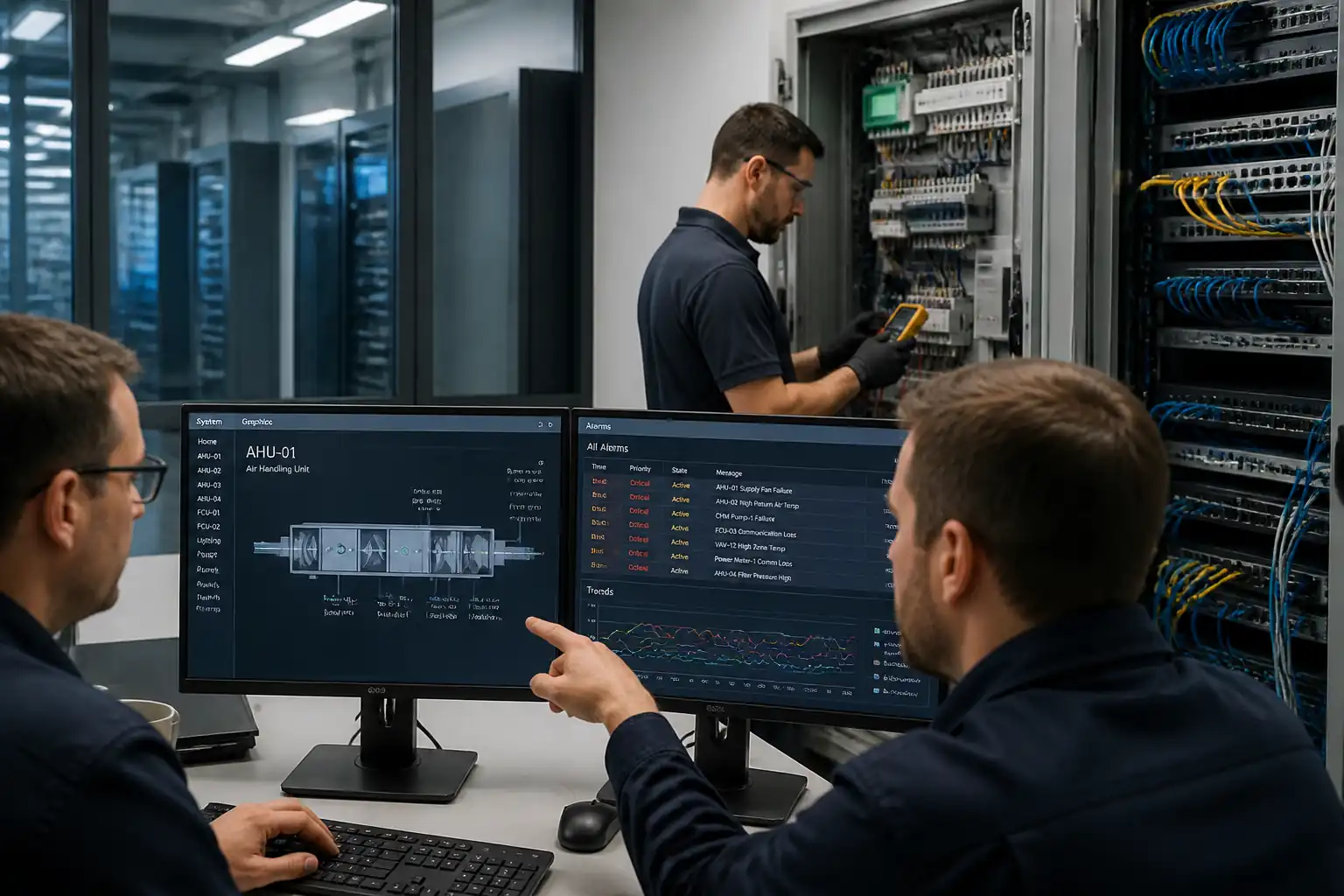
| 8 | Graphics/Alarms/Trending | Implement BMS graphics with live status, alarms, and trends; set alarm priorities with life-safety highest. | BMS Integrator | Client review |
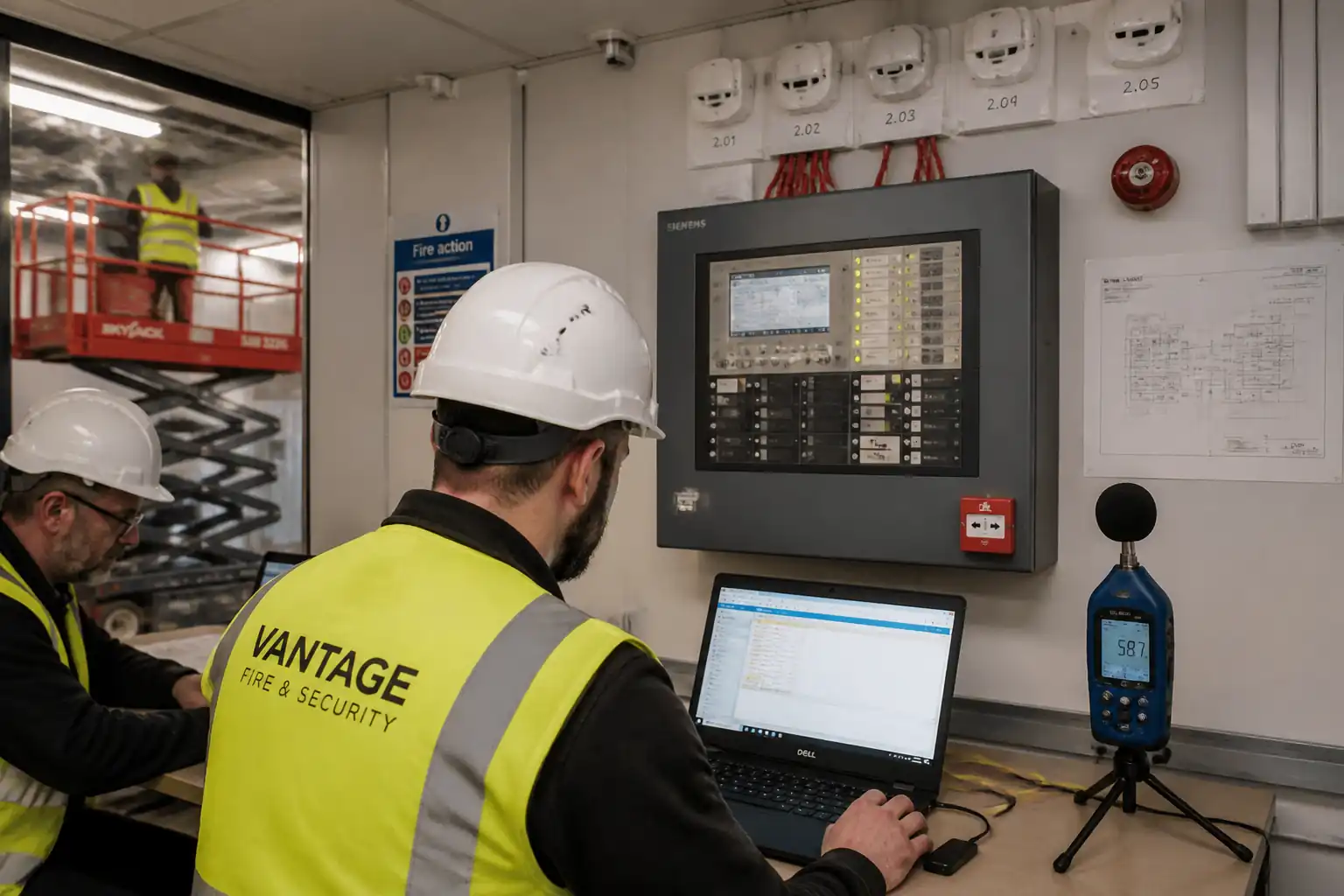
| 9 | Fire Alarm Interface Pre-Test | Dry-run fire interface using test mode outputs; verify command routing and lockouts without affecting occupants. | FAS Specialist, BMS Integrator | Witness by QA/QC |
| 10 | Cause & Effect End-to-End Testing | Execute approved scenarios by zone: fans, dampers, reliefs, door holders, AHU shutdowns, lifts interface (as applicable). | Commissioning Manager, FAS Specialist, BMS Integrator | HOLD point – Consultant/AHJ witness |
| 11 | Fail-Safe & Blackout Tests | Test power loss, network loss, and controller failover; verify default safe positions and recovery. | Commissioning Manager, BMS Integrator | Witness by Consultant |
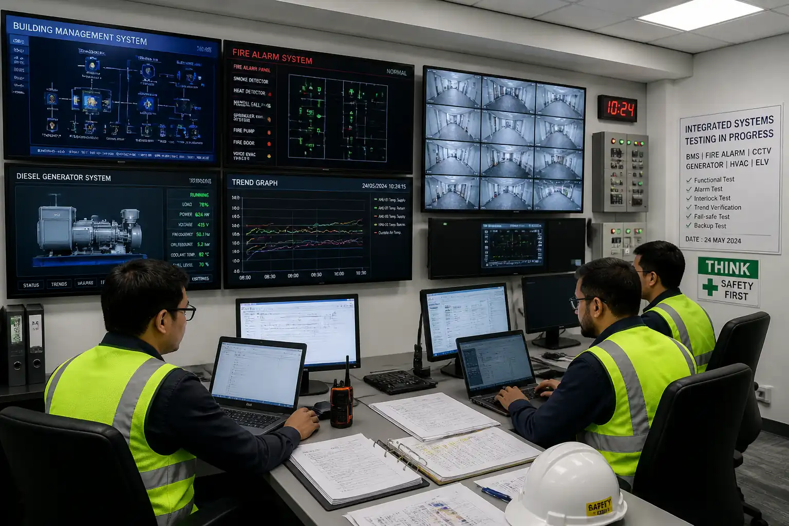
| 12 | Integrated System Test (IST) | Multi-discipline IST validating cross-system interactions including security/access, lifts, power, and ventilation impacts. | Commissioning Manager | HOLD point – AHJ/Consultant witness |
| 13 | Training & Handover | Train FM staff; deliver O&M manuals, as-builts, software backups; finalize snag rectifications. | BMS Integrator, Main Contractor | Client sign-off |
Health, Safety, and Environment (HSE) – Safety Controls
Task-Specific Hazards and Controls
1) Hazard: Live electrical exposure during panel energization and VFD testing
- Likely consequence: Electric shock, arc flash, burns
- Engineering/procedural control: LOTO for isolation; test with approved meters; barriers on live sections; arc-flash study boundaries if available; use suitably rated test leads.
- Required PPE: Arc-rated gloves/clothing (as required), insulated gloves, safety glasses/face shield, safety footwear
- Collective preventive measure: Temporary barriers and warning signage; restrict access; dedicated test area demarcation
- Inspection/permit/supervision: Electrical work permit; supervisor oversight; pre-job briefing and toolbox talk
2) Hazard: Unexpected fan start/rapid pressurization
- Likely consequence: Contact injuries, door slam, fall hazard near openings
- Engineering/procedural control: Pre-start announcements; lock open test doors; use hold-open devices where safe; gradual ramp where permissible except in fire mode testing
- Required PPE: Helmets, gloves, eye protection
- Collective preventive measure: Exclusion zones around fans/shafts; secure grilles/covers
- Inspection/permit/supervision: Commissioning plan approval; spotter assigned; supervisor sign-off
3) Hazard: Rotating equipment and VFDs in fire override
- Likely consequence: Entanglement, mechanical injury
- Engineering/procedural control: Guards in place; no loose clothing; verify direction of rotation with power off-guard removed then re-install before run
- Required PPE: Gloves, eye protection
- Collective preventive measure: Physical guards; barriers
- Inspection/permit/supervision: Pre-run mechanical inspection; OEM witness where required
4) Hazard: Working at height (damper access at ceilings/shafts)
- Likely consequence: Falls, dropped objects
- Engineering/procedural control: Use certified platforms; 3 points of contact; tool lanyards; no overreach
- Required PPE: Harness where needed, helmets with chin strap, safety footwear
- Collective preventive measure: Edge protection; exclusion zone below
- Inspection/permit/supervision: Working at Height permit; equipment inspection tags
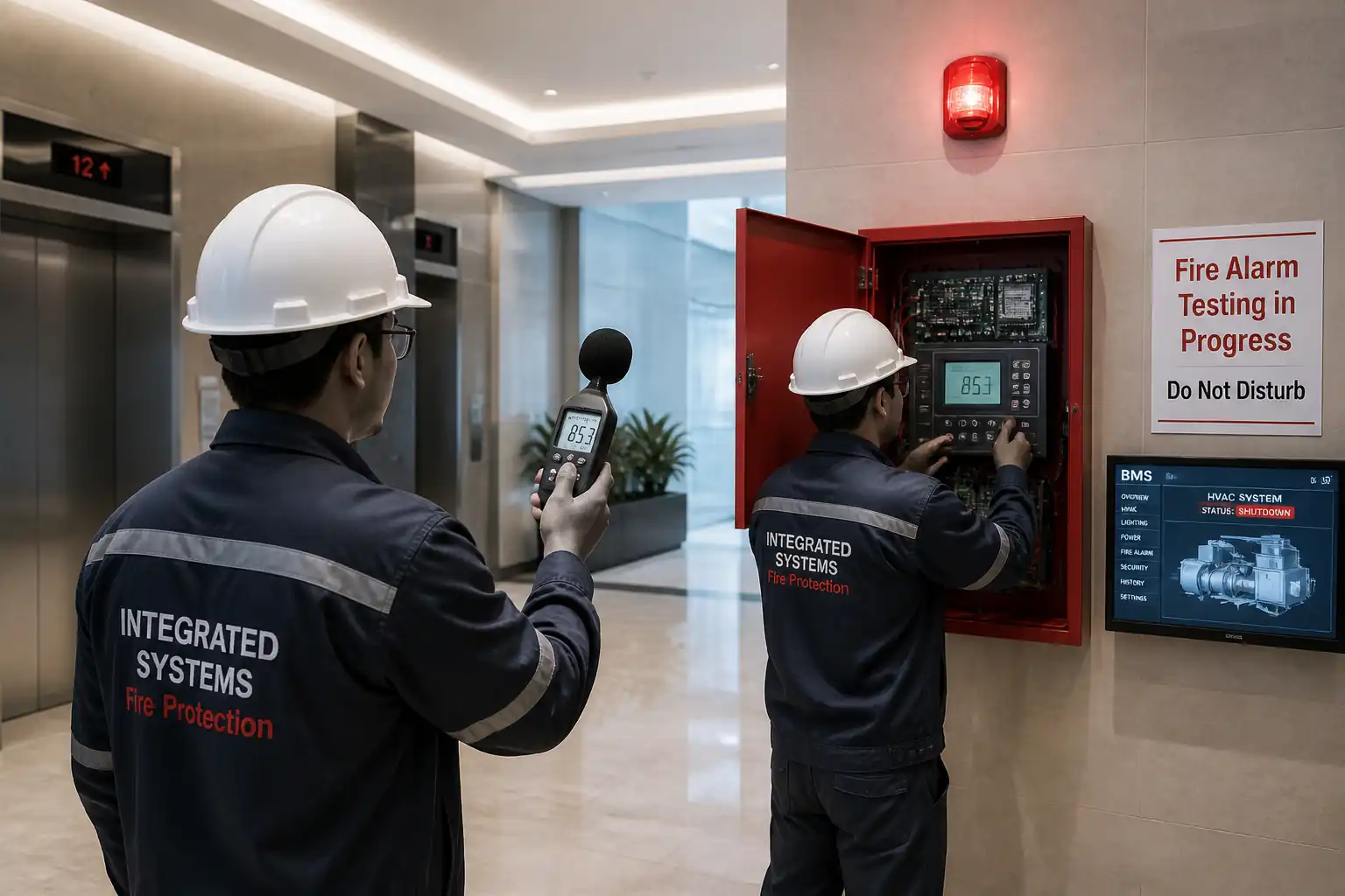
5) Hazard: Fire alarm impairment and public nuisance alarms
- Likely consequence: Delayed emergency response; occupant distress
- Engineering/procedural control: Approved impairment plan; isolate only affected zones; notify stakeholders; fire watch if required
- Required PPE: Standard site PPE
- Collective preventive measure: Coordination with security/operations; controlled test windows
- Inspection/permit/supervision: Fire system impairment permit; logbook entries; AHJ/Client notification
6) Hazard: Noise/vibration from test runs
- Likely consequence: Hearing damage, occupant disturbance
- Engineering/procedural control: Schedule off-hours; limit exposure duration; maintain equipment balance
- Required PPE: Hearing protection where >85 dBA
- Collective preventive measure: Acoustic screens where feasible
- Inspection/permit/supervision: Noise assessment; HSE monitoring
7) Hazard: Network/security risks during BMS integration
- Likely consequence: Unauthorized access, system instability
- Engineering/procedural control: Use approved VLANs; strong credentials; change default passwords; follow cyber policy
- Required PPE: N/A
- Collective preventive measure: IT change control and backups
- Inspection/permit/supervision: IT change request; configuration audit
[Verify per project HSE plan and local regulations]
Environmental Controls
- Energy and noise management: Conduct high-speed fan tests during off-peak hours; limit test duration; verify vibration isolation to minimize structure-borne noise.
- Air discharge: For smoke exhaust testing without actual smoke, keep dampers set to test airflow only. If theatrical smoke is required by AHJ, use water-based fluid and prevent nuisance emissions via temporary discharge routing and notifications. [Verify]
- Waste: Remove packaging and offcuts daily; segregate e-waste (failed sensors, boards) for certified disposal.
- Spills: Store oils/cleaners in trays; immediate cleanup with spill kits.
- Dust control: Minimal expected; maintain housekeeping and cap open ducts after testing to avoid contamination.
- Environmental compliance: Do not leave systems in override post-test; return to normal to avoid unnecessary energy use and emissions.
- Records: Keep environmental logs where required by the project EMS.
QA/QC Requirements
Quality Objectives
- Demonstrate that smoke control sequences operate per the approved Fire Strategy and Cause & Effect Matrix under normal and fail-safe conditions.
Key Acceptance Metrics
- Response time: Fire command to equipment action ≤10 s; full pressure/airflow established ≤60 s [Verify per design].
- Pressure differential: Stair/lobby pressurization typically 45–60 Pa; door opening force ≤100 N (EN) or per local code [Verify].
- Sensor accuracy: ≤±0.5% FS (or per manufacturer) after field calibration.
- Damper operation: Full travel within OEM-rated time (typically ≤75 s); correct end-switch feedback; fail-safe to design position.
- Redundancy/fail-safe: Loss of power/comm results in safe default or maintained life-safety operation.
- Alarms/trending: Correct priorities; trend resolution typically 1-min intervals with ≥30 days retention [Verify].
Documentation and Records
- Pre-functional checklists, I/O loop sheets, calibration certificates (ISO/IEC 17025 traceable), as-built drawings, software backups (version-controlled), C&E test records, fail-safe/IST dossiers, training records, O&M manuals.
- Nonconformance control: NCRs raised with corrective actions; retest results attached.
Change Control
- Any sequence or parameter changes post-approval require logged change request, review by Consultant, and updated as-built and backups.
Witnessing Protocol
- Hold points: Cause & Effect End-to-End Testing; Integrated System Test (IST).
- Witness points: Damper functional tests; Fan/VFD fire mode tests; Pressure tuning.
[Verify per project specifications]
Attachments
- Approved Cause & Effect Matrix (latest revision)
- Fire Strategy Report and Schematics
- BMS Point List and I/O Schedules
- Network Architecture Diagrams and BACnet Object Lists (PICS)
- Pre-functional and Loop Check Forms (templates)
- Calibration Certificates (ISO/IEC 17025 traceable)
- Damper/Fan/VFD OEM Start-up Sheets
- IST Procedures and Scripts
- O&M Manuals and As-built Drawings (PDF + native formats)
- Software Backups and Version Logs
- Training Materials and Attendance Sheets
- HSE Permits and Risk Assessments for Testing
This content is a read-only public reference. Download or customize to get an editable version.
ITP preview
The first inspection activities from the linked ITP for Method Statement: BMS Integration with Smoke Control Systems and Fire Alarm Interface:
| Activity | Inspection / Test | Acceptance Criteria | Responsibility | Record |
|---|---|---|---|---|
| Materials and Devices Receipt Inspection | ||||
| Materials and Devices Receipt Inspection | Check certificates, model numbers, listings (EN 12101-8/UL 555S for dampers; VFD fire mode), calibration certificates. | Devices match approved submittals; certificates valid and compliant. | QA/QC, BMS Vendor, Electrical Subcontractor | Material Inspection Reports; Certificates |
| Installation Verification | Visual checks for segregation, labeling, fire-stopping, earthing, enclosure ratings. | Conforms to drawings/specs; no damage; correct labels and terminations. | QA/QC, Electrical Supervisor | Pre-functional Checklists; Photos |
Showing 3 of 16 inspection activities. View full ITP →
Related Inspection and Test Plan
An Inspection and Test Plan (ITP) is available for Method Statement: BMS Integration with Smoke Control Systems and Fire Alarm Interface. The ITP defines the inspection activities, acceptance criteria, hold and witness points, responsible parties, and records required to verify the work described in this method statement.
View the Method Statement: BMS Integration with Smoke Control Systems and Fire Alarm Interface ITP →Frequently asked questions
Continue with related Quollnet resources connected to this method statement.