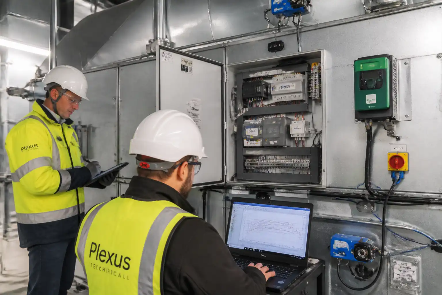

Inspection and Test Plan for Method Statement: BMS Controls Installation and Functional Testing for Air Handling Units (AHUs)
AI-assisted inspection and test plan connected to a method statement, with PDF and Excel export.
More than a static template
Unlike a downloadable Word or PDF template, this ITP is an AI-assisted editable starting point directly connected to its method statement. Every inspection activity, hold point, and acceptance criterion is structured and ready to adapt to your project.
- AI-assisted customization — Tailor inspection activities and acceptance criteria to your specific project scope.
- Linked method statement — This ITP is connected to the corresponding method statement describing the work sequence.
- Multiple export formats — Download as a formatted PDF or editable Excel spreadsheet.
- Editable starting point, not a final document — Review and verify all content against your project specifications and standards before use.
What you can customize
When you save this ITP to your account, every inspection row becomes editable. You can add, remove, or modify:
- Inspection activity — Description of what is being inspected.
- Inspection type — Hold point (H), Witness point (W), Review (R), or Monitor (M).
- Responsibility — Contractor, subcontractor, engineer, or client.
- Frequency — How often the inspection occurs.
- Acceptance criteria — Referenced standard or specification requirement.
- Records — Forms, test reports, or checklists required as evidence.
Why this ITP is used
To ensure that installation and commissioning of AHU BMS controls meet approved designs, standards, and performance criteria.
Who uses this inspection and test plan
BMS contractor, QA/QC engineer, commissioning manager, consultant/client representative, and HSE officer.
When this ITP is prepared and submitted
From material receipt and installation through pre-functional checks, functional testing, and final witnessed performance verification.
Who receives or approves this ITP
Consultant/Client for review, witnessing, and acceptance.
Inspection scope
Materials, panel installation, wiring, device mounting, network integrity, I/O calibration, safeties, VFD interface, sequences, and integrated performance.
Typical hold, witness, and review points
Fire/smoke interface tests (Hold), safety interlocks (Witness), network discovery (Witness), VFD interface (Witness), final performance verification (Hold/Witness).
Typical inspection records
MIRs, IRs, loop/point sheets, calibration certificates, network logs, functional test reports, trend exports, witness forms, as-builts, O&M.
Important approval note
This ITP is an AI-assisted editable starting point, not a pre-approved document. Before use on any project, all inspection activities, hold points, and acceptance criteria must be reviewed and approved by the relevant parties (superintendent, principal contractor, or client representative) in accordance with your contract and project quality plan.
Always verify acceptance criteria against your applicable drawings, specifications, and regulatory requirements. Hold points must be confirmed with the relevant authority before work proceeds past that point.
Inspection and test plan
| Activity | Inspection / Test | Acceptance Criteria | Responsibility | Record |
|---|---|---|---|---|
| Material receipt inspection (devices/panels) | Check make/model vs. approvals; certificates; damage | Compliance with approved submittals; intact packaging; IP rating per environment; calibration certs present. | QA/QC Engineer (C) / Consultant (W) | MIR, delivery inspection report |
| Control panel installation and power | Mounting, earthing, segregation, torque, labels | Level/plumb; earth continuity <1 Ω; correct labeling; IP maintained; no damage. | Electrical Supervisor (C) / QA/QC (C) / Consultant (W) | IR, photos |
| Cable containment and routing | Visual inspection; segregation distances | Segregation LV/ELV maintained; bends within radius; supports at specified spacing [Verify]. | Controls Electrician (C) / QA/QC (C) | IR, redlines |
| Device installation (sensors/actuators) | Location, orientation, access, linkage | Correct location/orientation; accessible; linkages full stroke; seals intact. | BMS Engineer (C) / QA/QC (C) / Consultant (W) | IR, photos |
| Pre-power tests (IR/continuity) | IR tests 500 V/250 V DC; continuity/earth | IR ≥ specified thresholds; continuity/polarity correct. | Electrical Supervisor (C) / QA/QC (C) | Electrical test sheets |
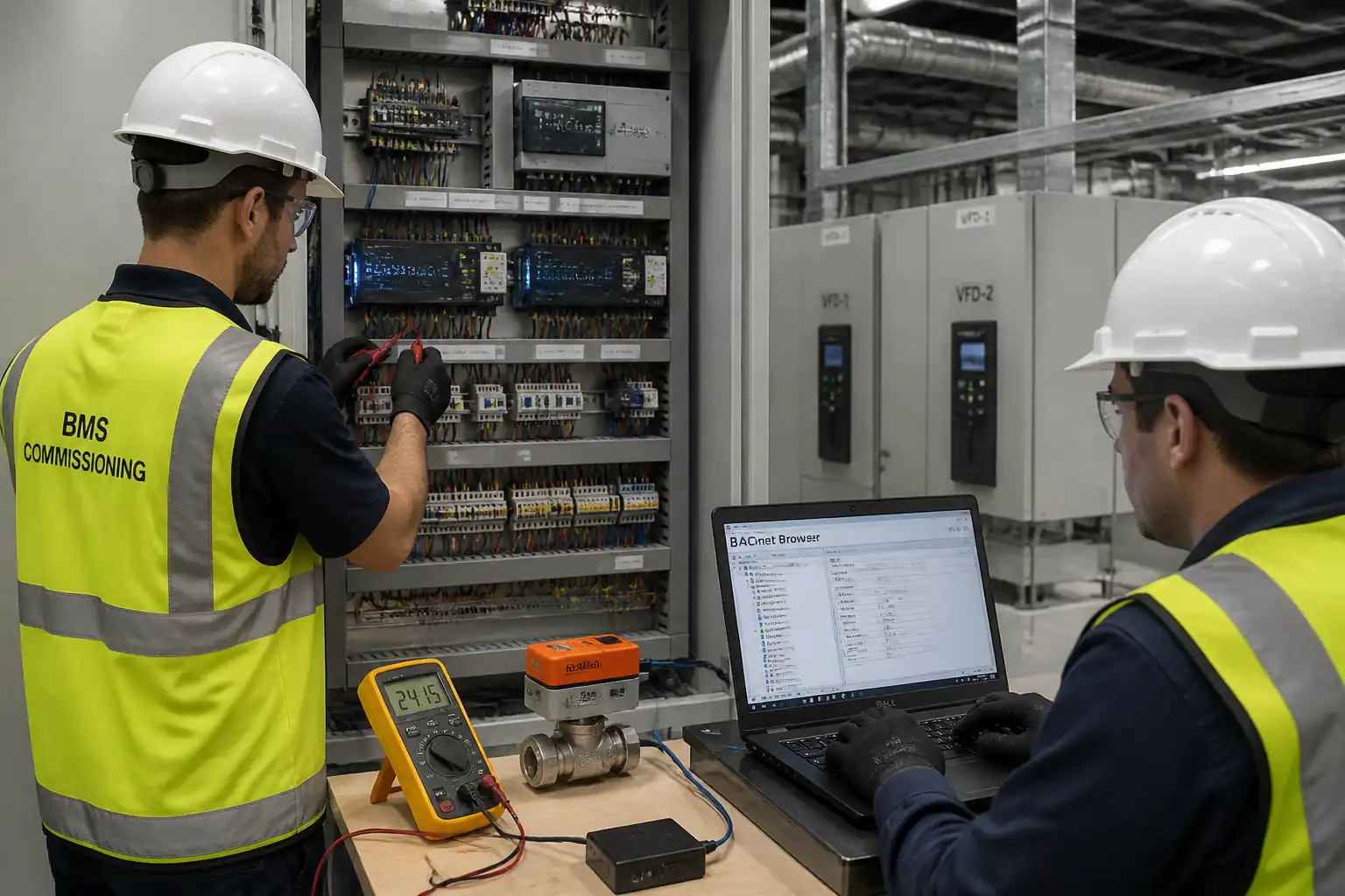
| Network checks (BACnet) | RS-485 resistance; device discovery; comms stability | ~60–65 Ω measured; all devices discovered; 0 CRC errors observed for 60 min [Verify]. | BMS Engineer (C) / Consultant (W) | Network log/screenshots |
| Loop checks and calibration (AI/AO) | Simulate 0/50/100% spans; temperature/humidity/DP calibration | Within device spec or ±1% FS; AO 2–10 V within ±0.2 V at endpoints [Verify]. | BMS Engineer (C) / QA/QC (C) / Consultant (W) | Loop sheets, calibration certs |
| Digital I/O and safeties | Simulate DI/DO; verify interlocks and latching | Correct responses within 5 s; latching and manual reset as per SoO. | BMS Engineer (C) / HSE (S) / Consultant (W) | Point test sheets, alarm logs |
| VFD interface and command verification | Start/stop, speed reference scaling, fault/run feedback | Start/stop reliable; AO scaling ±1% FS; run feedback within 2 s. | BMS Engineer (C) / VFD Tech (S) / Consultant (W) | VFD set-up sheet |
| Functional test – temperature control | Auto mode run; SAT stability and tuning | SAT ±1.0°C steady-state over 15 min; no sustained hunting; OA min within ±5% [Verify]. | BMS Engineer (C) / Commissioning Manager (S) / Consultant (W) | Functional test report, trends |
| Duct static/flow control (if applicable) | Static/flow setpoint and response to disturbances | ±5% of setpoint; recovery <60 s; stable VFD speed. | BMS Engineer (C) / TAB (S) / Consultant (W) | Trends, TAB note |
| Witnessed performance verification and sign-off | Integrated 60-min run; alarms; logging | Meets SoO KPIs; complete logs; zero critical alarms; documents complete. | Commissioning Manager (C) / Consultant (W) / Client (W) | Witness form, signed report, trend exports |
This table is a read-only public reference. Download the PDF or Excel version, or customize this ITP to edit it for your project.
Frequently asked questions
Related method statement
This Inspection and Test Plan is associated with the Method Statement: BMS Controls Installation and Functional Testing for Air Handling Units (AHUs) method statement, which describes the step-by-step construction sequence, resources, materials, equipment, safety controls, and environmental controls for this activity.
View the Method Statement: BMS Controls Installation and Functional Testing for Air Handling Units (AHUs) method statement →Continue with related inspection, method statement, article, and checklist resources.