
Method Statement: BMS Point-to-Point Testing and Verification – Method Statement
AI-assisted method statement with matching ITP, PDF download, and Excel export.
More than a static template
Unlike a downloadable Word or PDF template, this method statement is an AI-assisted editable starting point connected directly to a matching Inspection and Test Plan. Every section is structured, project-adaptable, and ready to export.
- AI-assisted drafting — Customize every section with AI for your specific project scope.
- Linked ITP — A matching inspection and test plan is generated alongside the method statement.
- Multiple export formats — Download as a formatted PDF or editable Excel spreadsheet.
- Editable starting point, not a final document — Review, verify, and adjust all content against your project requirements before use.
Static template vs. Quollnet workflow
| Feature | Static template | Quollnet |
|---|---|---|
| Project-specific content | Manual fill-in required | AI-assisted customization |
| Linked ITP | Separate document, no link | Matching ITP included |
| Export formats | Usually PDF only | PDF and Excel |
| Structured sections | Free-form layout | 13 standardized sections |
| Saved to your account | Local file only | Cloud-saved, reusable |
| Content accuracy | You verify everything | AI-assisted, you still verify |
| Cost | Often free but time-intensive | Free to customize and download |
What you can customize
When you save this method statement to your account, every section becomes editable. The following 13 sections are included:
- Scope — Defines the activity and its boundaries.
- References — Standards, specifications, and drawings.
- Responsibilities — Roles and accountabilities.
- Resources — Labour, plant, and equipment summary.
- Materials — Materials and compliance requirements.
- Equipment — Tools and equipment details.
- Prerequisites — Hold points and pre-conditions.
- Method sequence — Step-by-step construction sequence.
- Safety controls — HSE risk controls and PPE.
- Environmental controls — Environmental mitigation measures.
- QA/QC — Quality inspection and test requirements.
- ITP — Inspection and Test Plan table (has its own page).
- Attachments — Referenced drawings and documentation.
Why this method statement is used
This method statement is used to define and communicate the approved procedure for carrying out method statement: bms point-to-point testing and verification on site. It ensures the work is planned in advance, the correct resources and controls are in place, and all personnel understand responsibilities, sequence, quality requirements, and safety controls before work begins. It aligns site execution with the documented scope and acceptance expectations.
Who uses this method statement
This method statement is used by contractors, site supervisors, project engineers, QA/QC engineers, HSE officers, consultants, and client representatives. It serves as a shared reference for planning, execution, supervision, inspection, and approval of the activity on site.
When it is prepared and submitted
The method statement is prepared before the work activity starts and submitted as part of the pre-construction documentation package for review and approval.
Who reviews or approves it
The method statement is usually submitted to the client representative, consultant, resident engineer, or project management consultant for review and approval before the work commences.
Important approval note
This method statement is an AI-assisted editable starting point, not a pre-approved document. Before use on any project, all content must be reviewed and approved by the relevant parties (superintendent, principal contractor, or client representative) in accordance with your contract and project quality plan.
For example: if your specification requires a departure from a referenced standard, that departure must be documented and approved separately — this method statement will not capture that automatically. Always verify against your applicable drawings, specifications, and regulatory requirements.
Method statement content
Scope
Overview
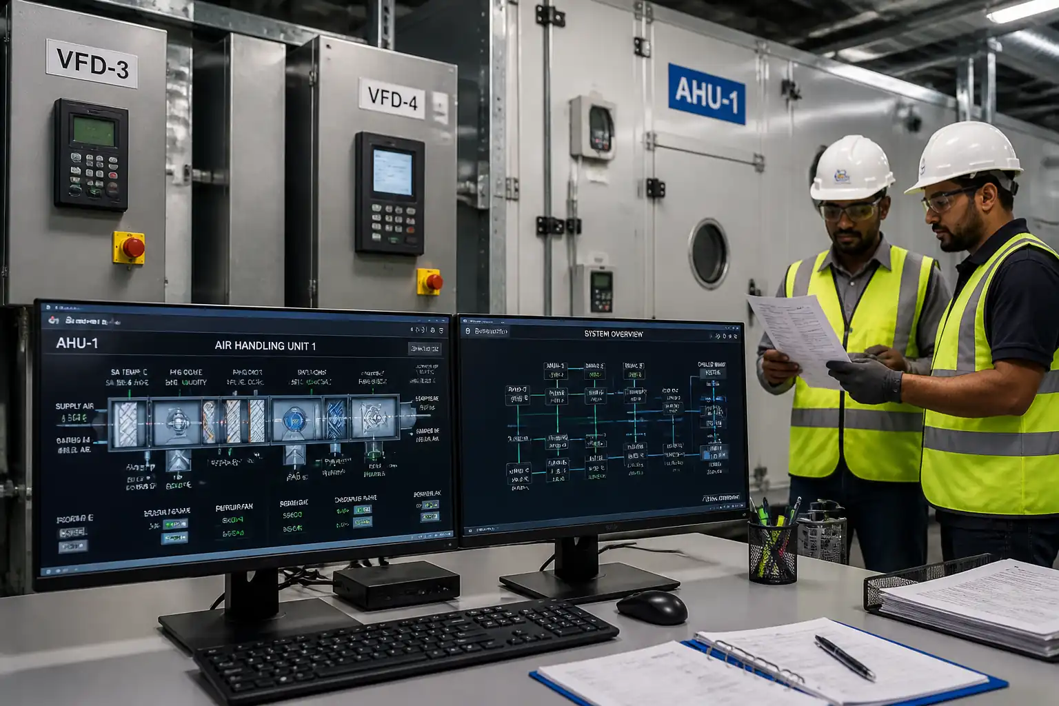
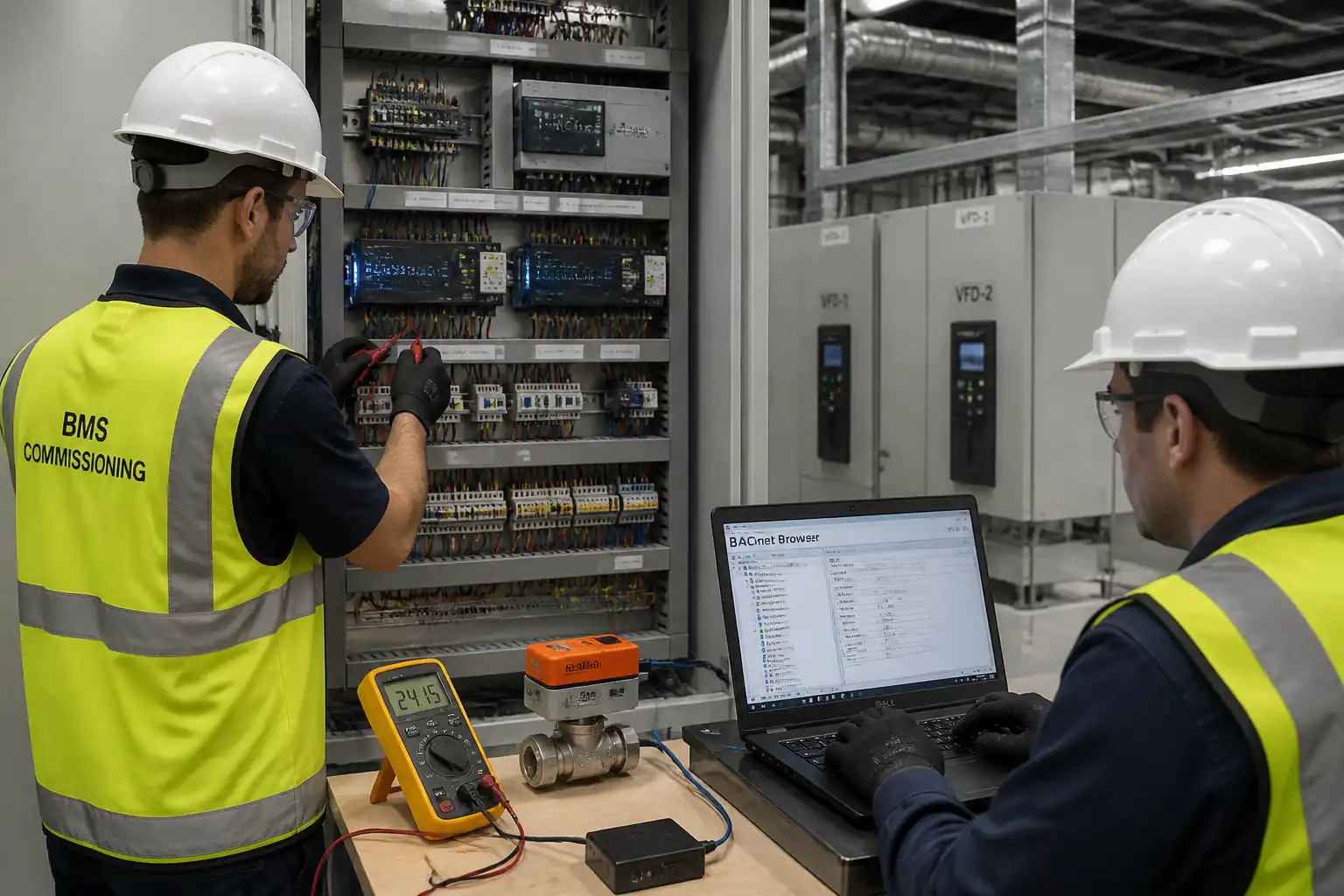
This method statement covers pre-functional checks and point-to-point (PTP) testing for Building Management System (BMS) input/output (I/O) across control panels and field devices, including:
- Verification of wiring, labeling, terminations, power, earthing, and segregation.
- Functional testing of all input types (analog, digital, pulse, networked) and output types (analog, digital), including scaling, polarity, direction, fail-safe state, and interlocks.
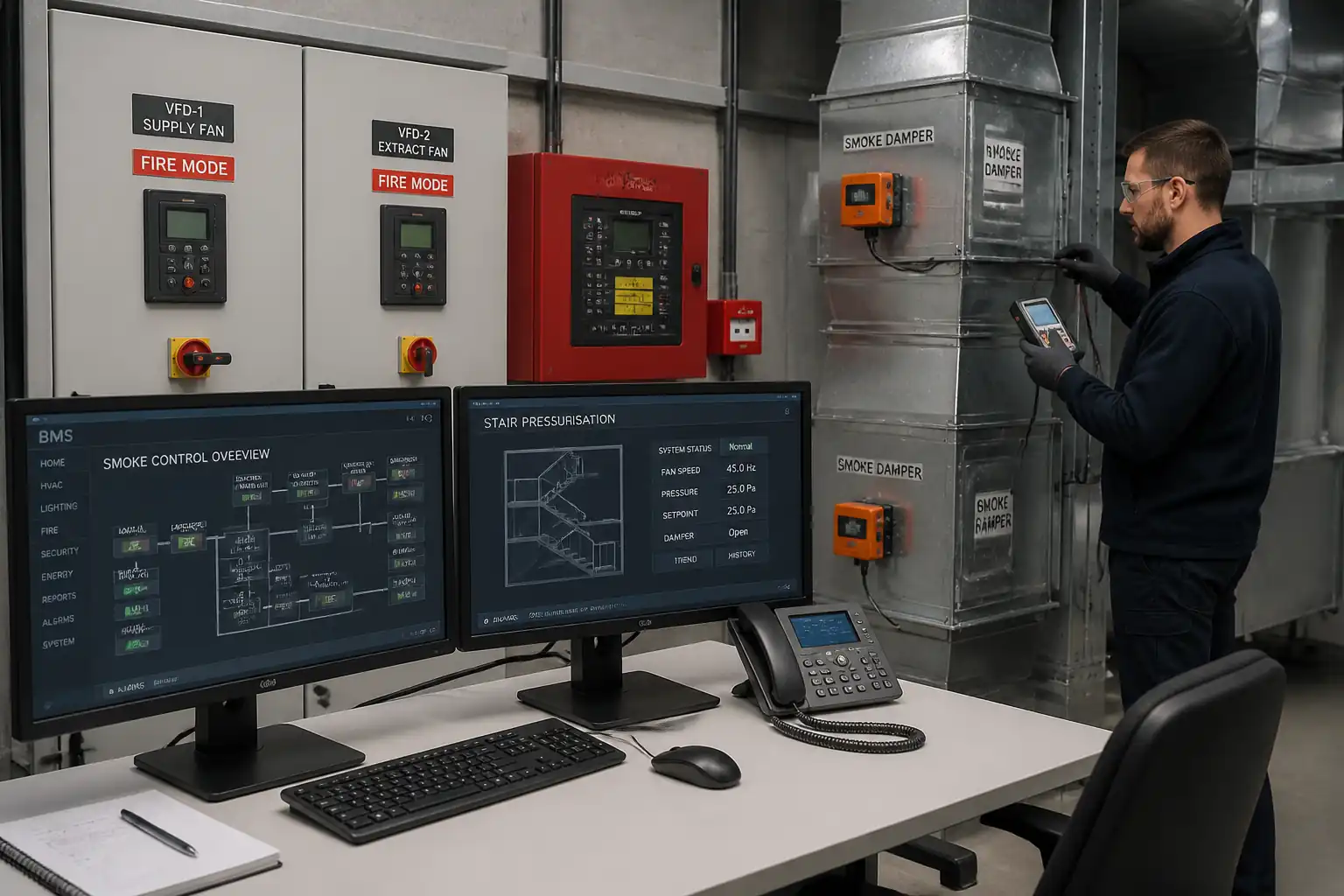
- Status feedback confirmation of interlocked devices (e.g., valve end switches, VFD run/fault, fire alarm interfaces).
- Actuator command testing (valves, dampers, VFDs) and confirmation of travel, direction, stroke time, and safeties.
- Network integration checks (e.g., BACnet, Modbus), object mapping, priorities, and alarm routing.
- Defect logging, wiring correction, re-test, test sheet completion, QA/QC hold points, consultant witnessing, and signed records.
Systems/Locations
- BMS control panels (MCC/LCU/FCU/AHU/Plant rooms, risers, rooftops).
- Field devices: temperature, humidity, pressure, flow, CO/CO2 sensors, differential pressure switches, valve/damper actuators, VFDs, meters.
- Third-party interfaces: chillers, boilers, VFDs, meters, Fire Alarm System (FAS), lifts (if applicable), lighting control, security interfaces [Verify per project scope].
Exclusions
- Software sequence tuning and full functional performance testing (FPT) beyond confirmation of I/O responsiveness and basic interlocks—covered under separate FPT method.
- Permanent network cybersecurity hardening—covered by project ICT policy.
Deliverables
- Signed PTP test sheets for 100% of points.
- Snag/defect list with close-out evidence.
- Redlined I/O schedules and as-built point lists.
- Witnessing records and ITP compliance evidence.
References
| Document Type | Reference / Number | Revision | Notes |
|---|---|---|---|
| Standard | CIBSE Code C | Guidance for automatic control commissioning. | |
| Guidance | BSRIA BG Series | Practical commissioning procedures. | |
| Standard | ANSI/ASHRAE 135 | Object types, services, device/point mapping. | |
| Standard | IEC 61158 / Modbus Application Protocol | For third-party integrations where specified. | |
| Code | IEC 60364 / BS 7671 / NFPA 70 (NEC) | Select applicable national code [Verify per project specifications]. | |
| Standard | ISA-5.1 | Point tagging and documentation conventions. | |
| Standard | ISO/IEC 17025 / ISO 9001 | Calibration certificates for test instruments. | |
| Standard/Regulation | ISO 45001; NFPA 70E or equivalent | Arc-flash and energized panel precautions where applicable. |
Responsibilities
| Role | Responsibility | Name / Party |
|---|---|---|
| Commissioning Manager | Commissioning Manager | Main Contractor |
| BMS Lead Engineer | BMS Lead Engineer | BMS Vendor |
| Technician | BMS Technicians / Electricians | BMS Vendor/Subcontractor |
| Supervisor | Mechanical Supervisor / Vendor Reps | MEP Contractor / OEM |
| QA/QC Engineer | QA/QC Engineer | Main Contractor |
| HSE Officer | HSE Officer | Main Contractor |
| Consultant | Consultant / Employer’s Representative | Engineer/Employer |
Resources
| Resource Type | Description | Quantity | Remarks |
|---|---|---|---|
| Personnel | Leads commissioning | 1 | |
| Personnel | Leads BMS technical | 1 | |
| Personnel | Field testing crew | 2–6 [Verify per project] | |
| Personnel | Panel/field terminations | 2–4 [Verify per project] | |
| Personnel | Plant interface & safeties | 1–3 | |
| Personnel | Quality verification | 1 | |
| Personnel | HSE oversight | 1 |
Materials
| Material | Specification / Grade | Quantity | Remarks |
|---|---|---|---|
| LSZH/CM/CMR control cable per spec | Twisted pair/shielded for AI/communications; color coding per spec | As required | |
| DIN terminals & accessories | IEC 60947 compliant | As required | |
| Span/zero gas | Concentration per sensor range [Verify] | As required | |
| Precision resistors | Value per design/shop drawings | Assorted kit |
Equipment
| Equipment | Capacity / Type | Quantity | Inspection Required |
|---|---|---|---|
| Digital Multimeter | CAT III 600 V or better | 2–4 | |
| Process calibrator | 24 V loop power; mA/V output | 1–2 | |
| Decade box / RTD simulator | 10–10k Ω range | 1 | |
| Laptop | Network adapters, MSTP USB converter | 1–2 | |
| Insulated tools | Up to 1000 V insulation | Sets as needed | |
| VFD tool | As required | ||
| Working at height gear | SWL per equipment | As required |
Prerequisites
- Approved shop drawings, I/O schedules, panel GA/SLD, device datasheets, network architecture diagrams.
- Approved Method Statement and ITP; risk assessment and PTW/LOTO arrangements in place.
- Controllers configured with baseline database; point names/units/scaling preloaded; latest firmware approved.
- All permanent power to panels/field devices available and commissioned; temporary supplies avoided unless approved.
- Completion of mechanical/electrical pre-commissioning for related plant (lubrication, rotation checks, safeties, direction of rotation for fans/pumps, leakage checks) with clearance for test.
- Instruments and tools calibrated with valid certificates (within 6–12 months typical) [Verify per project QA/QC plan].
- Communication trunks installed, terminated, and labeled; MAC/Device IDs assigned; IP addresses reserved; time sync source identified.
- Fire alarm cause & effect available; protocols for disabling/nuisance alarms agreed with FAS team.
- Witness schedule agreed with Consultant; hold points notified minimum 48 hours in advance [Verify per contract].
Method Sequence
| Step | Activity | Description | Responsibility | Inspection / Hold Point |
|---|---|---|---|---|
| 1 | Site setup and safety briefing | Establish work zones, signage, and access; conduct toolbox talk focused on energized panel work and auto-start hazards; confirm permits and LOTO plan. | Commissioning Manager / HSE Officer | PTW/LOTO verification; access equipment tagged |
| 2 | Documentation and database verification | Verify latest drawings/I/O schedules vs. controller database; confirm point naming, engineering units, and scaling; back up baseline database. | BMS Lead Engineer | Desk check; peer review |
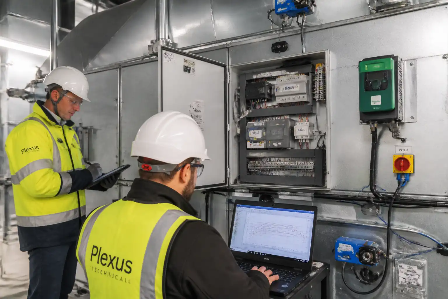
| 3 | Panel inspection (pre-energization) | Visual check of mounting, wiring, segregation (LV/ELV), labeling, earthing, ferruling, cable dressing, fuse ratings, terminal torque; confirm spare capacities and ventilation. | QA/QC Engineer with BMS Technician | Panel inspection |
| 4 | Energization checks | Apply power to panel; verify power supply levels (e.g., 230 VAC, 24 VAC/DC), controller boot, network status LEDs, UPS where fitted; confirm no abnormal heating/smell. | BMS Lead Engineer / Electrician | Voltage measurements |
| 5 | Field wiring verification | Check device model, location, tag, cable type, junction boxes; verify termination polarity/shield drain; confirm screen grounded one end only unless specified otherwise. | BMS Technician | Field inspection |
| 6 | Analog input (AI) testing | Isolate device if needed; inject simulated signals: 4–20 mA, 0–10 V, RTD/NTC equivalent resistances; verify DDC reading, scaling, filtering, and engineering units. | BMS Technician with BMS Engineer | Live read verification |
| 7 | Digital input (DI) testing | Simulate contact open/close using approved jumpers or device actuation (e.g., DPS tubing pinch); confirm status in DDC and alarm logic (normal/fault). | BMS Technician | Point state verification |
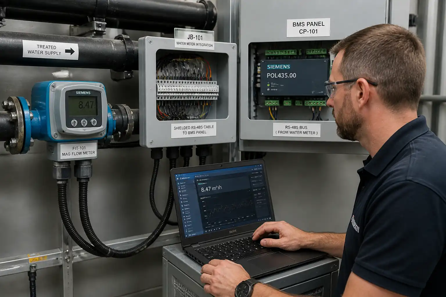
| 8 | Pulse input testing (meters) | Inject pulse train or actuate meter to verify count, scaling (kWh/m³), and debounce settings. | BMS Engineer | Trend/log review |
| 9 | Analog output (AO) testing | Command 0–10 V or 4–20 mA output at 0/50/100%; measure at terminal; verify downstream device response (e.g., actuator travel, VFD speed). | BMS Engineer / Technician | Measurement and functional check |
| 10 | Digital output (DO) testing | With safeties in place and plant permitted, issue run/stop or open/close commands; verify HOA positions; confirm end-switch or status feedback; confirm fail-safe state on loss of signal/power. | BMS Engineer / Mechanical Supervisor | Functional test |
| 11 | Interlocks and safety chain verification | Verify DPS, freezestat, flow switch, smoke/fire shutdown, VFD trips; simulate using approved methods or vendor tools; coordinate with FAS to avoid nuisance alarms. | BMS Engineer / FAS Engineer / OEM | Cause & effect check |
| 12 | Network and integration verification | Verify BACnet/Modbus device discovery, object IDs, units, priorities, COV subscriptions; check MSTP MAC uniqueness and baud; verify time sync and trend/alarm routing. | BMS Lead Engineer | Protocol browser review |
| 13 | Labeling and documentation update | Apply missing labels/ferrules; update redlines; synchronize point database; update O&M drafts. | BMS Technician / QA/QC | Visual/document audit |
| 14 | Defect rectification and re-test | Log snags; correct wiring/scaling; re-test affected points; update records. | BMS Lead Engineer / Technicians | QA/QC review |
| 15 | Consultant witnessing and close-out | Present completed PTP sheets, calibration certs, and checklists; repeat sample tests as requested; obtain signatures and approvals. | Commissioning Manager / Consultant | Formal witnessing |
Safety Controls
Task-specific hazards and controls
- Hazard: Energized panels (LV/ELV) exposure and potential arc flash
- Likely consequence: Electric shock, burns, arc-flash injuries
- Engineering/procedural control: Permit-to-Work; LOTO for non-live tasks; energized work only when functionally necessary with written authorization; barriers and insulated mats; use insulated tools; verify absence of voltage before contact; maintain minimum approach distances [Verify per project HSE plan and local regulations]
- Required PPE: Arc-rated clothing (CAT 2 or per study), insulated gloves (Class 00/0 for up to 500/1000 V), safety glasses/face shield, dielectric footwear
- Collective preventive measure: Panel doors interlocked; RCDs/RCBOs; lockable isolators; task sequencing to minimize live exposure
-
Inspection/permit/supervision: Electrical PTW; LOTO log; pre-use tool inspection; competent person supervision; arc-flash label review
-
Hazard: Unexpected auto-start of rotating equipment during DO testing
- Likely consequence: Entanglement, impact injuries
- Engineering/procedural control: Announce start; establish exclusion zones; confirm HOA to Auto; verify safeties functional; use spotter/communication
- Required PPE: Hard hat, safety boots, high-visibility vest, gloves
- Collective preventive measure: Barriers and signage; local E-stop confirmed
-
Inspection/permit/supervision: Permit for functional testing; supervisor present; OEM vendor engaged for VFDs/chillers
-
Hazard: Working at height (rooftop AHUs, risers)
- Likely consequence: Falls from height
- Engineering/procedural control: Use inspected ladders/podiums/MEWPs; maintain three-point contact; anchor points and fall arrest where required; avoid overreach
- Required PPE: Full-body harness with lanyard (when required), helmet with chin strap
- Collective preventive measure: Guardrails/toeboards; properly erected mobile towers with tags
-
Inspection/permit/supervision: Work at Height permit; equipment inspection tags; trained operators only
-
Hazard: Interface with fire alarm during interlock tests
- Likely consequence: Unwanted alarms/evacuations, system disablement risk
- Engineering/procedural control: Coordinate with FAS team; place systems in test mode; notify stakeholders; revert to normal immediately after
- Required PPE: Standard site PPE
- Collective preventive measure: Centralized control room coordination; annunciation muted in test mode
-
Inspection/permit/supervision: FAS test permit/authorization; logbook entries
-
Hazard: Use of calibration gases (CO/CO2)
- Likely consequence: Asphyxiation at high concentrations; regulator mishandling injury
- Engineering/procedural control: Use in ventilated areas; secure cylinders; regulator check; leak test with soapy water; limit exposure time
- Required PPE: Safety glasses, nitrile gloves
- Collective preventive measure: Cylinder racks; SDS available
-
Inspection/permit/supervision: Gas cylinder inspection; certificate of analysis; COSHH assessment [Verify per local regulations]
-
Hazard: Manual handling of access equipment and panels
- Likely consequence: Strains/sprains, crush injuries
- Engineering/procedural control: Team lifts; use trolleys; keep pathways clear; weight rating checks
- Required PPE: Gloves, safety boots
- Collective preventive measure: Storage plans; housekeeping
-
Inspection/permit/supervision: Manual handling training; equipment inspection
-
Hazard: Data/network misconfiguration during live systems
- Likely consequence: Loss of building services, security exposure
- Engineering/procedural control: Backup before changes; change control approval; test on isolated segment where possible; strong passwords; disable default creds
- Required PPE: N/A (administrative control)
- Collective preventive measure: Network access control; role-based permissions
-
Inspection/permit/supervision: ICT change request; audit logs; supervision by BMS Lead Engineer
-
Hazard: Compressed air lines for DPS/flow proving
- Likely consequence: Eye injury, device damage
- Engineering/procedural control: Regulated low pressure; proper tubing adapters; gradual application
- Required PPE: Safety glasses
- Collective preventive measure: Barriers if near others
- Inspection/permit/supervision: Tool inspection; competent person use only
[Verify per project HSE plan and local regulations]
Environmental Controls
- Noise and disturbance: Schedule tests to minimize disruption; avoid nuisance alarms by coordinating with FAS; communicate with facility.
- Waste management: Collect cable offcuts, used ferrules, packaging; segregate recyclable materials; dispose of E-waste (faulty sensors/PCBs) via approved recycler [Verify per project EMS].
- Energy use: Avoid unnecessary plant running during tests; stop equipment immediately after verification; log runtime.
- Emissions: Use calibration gases sparingly; ensure good ventilation; cap cylinders and prevent leaks.
- Spill prevention: Use drip trays under AHUs/chilled water equipment when inspecting near piping; keep absorbents available.
- Dust and housekeeping: Maintain tidy work areas; close panel doors after work; remove temporary labels and debris daily.
- Data security: Protect exported logs and databases; store on project-approved repositories; no personal cloud use.
QA/QC
Quality controls
- Instruments calibration: All meters/simulators with valid ISO/IEC 17025 or equivalent traceable certificates; verify serial numbers on test sheets.
- Test coverage: 100% of physical I/O points; 100% of integrated/network points; minimum 3-point testing for analog signals (0/50/100%).
- Tolerances: Unless specified otherwise—mA/V signals ±0.5% FS typical; temperature ±0.5–1.0 °C; pulse counts ±1%; actuation times within OEM stated ranges [Verify per project specifications].
- Records: Unique point ID, location, device tag, instrument serials, input stimulus/command values, observed readings/feedback, pass/fail, comments, retest reference, tester initials, date/time stamps, and witness signatures where applicable.
- Nonconformities: Log in NCR register; categorize A/B/C; corrective actions with root cause; retest evidence attached.
- Software control: Maintain baseline backups before/after testing; version control with change logs.
- Sampling for witness: Consultant to witness sample per ITP; critical life-safety interlocks to be witnessed 100%.
- As-built updates: Redline I/O and network schedules during testing; issue controlled as-builts after close-out.
- Traceability: Cross-reference each test record to drawing number, controller ID, and terminal references.
Attachments
- Sample PTP test sheet template (fields: Point ID, Location, Device Tag, Type, Range/Units, Stimulus/Command, Observed Value/Status, Tolerance, Pass/Fail, Instrument ID, Tester, Date/Time, Witness, Comments).
- Panel pre-energization checklist.
- Interlock and cause & effect verification sheet.
- Network integration checklist (BACnet/Modbus) including device IDs and priorities.
- Calibration register and certificates for test instruments.
- Snag list/NCR form template.
- As-built I/O schedule and tagging legend (ISA-5.1 aligned).
This content is a read-only public reference. Download or customize to get an editable version.
ITP preview
The first inspection activities from the linked ITP for Method Statement: BMS Point-to-Point Testing and Verification:
| Activity | Inspection / Test | Acceptance Criteria | Responsibility | Record |
|---|---|---|---|---|
| Method statement and ITP approval | Review and approval of documents | Approved MS/ITP before work commences | Commissioning Manager / Consultant | Approved MS/ITP copies |
| Panel pre-energization inspection (HP1) | Visual, torque spot-checks, earthing continuity | Labeling complete; terminations secure; fuses correct; enclosure integrity | QA/QC Engineer | Panel inspection sheet; photos |
| Energization checks (W1) | Voltage and PSU checks; controller/network status | Voltages within limits; correct polarity; no faults | BMS Lead Engineer | Commissioning log |
Showing 3 of 11 inspection activities. View full ITP →
Related Inspection and Test Plan
An Inspection and Test Plan (ITP) is available for Method Statement: BMS Point-to-Point Testing and Verification. The ITP defines the inspection activities, acceptance criteria, hold and witness points, responsible parties, and records required to verify the work described in this method statement.
View the Method Statement: BMS Point-to-Point Testing and Verification ITP →Frequently asked questions
Continue with related Quollnet resources connected to this method statement.