
Method Statement: Water Meter Integration with Building Management System (BMS) – Method Statement
AI-assisted method statement with matching ITP, PDF download, and Excel export.
More than a static template
Unlike a downloadable Word or PDF template, this method statement is an AI-assisted editable starting point connected directly to a matching Inspection and Test Plan. Every section is structured, project-adaptable, and ready to export.
- AI-assisted drafting — Customize every section with AI for your specific project scope.
- Linked ITP — A matching inspection and test plan is generated alongside the method statement.
- Multiple export formats — Download as a formatted PDF or editable Excel spreadsheet.
- Editable starting point, not a final document — Review, verify, and adjust all content against your project requirements before use.
Static template vs. Quollnet workflow
| Feature | Static template | Quollnet |
|---|---|---|
| Project-specific content | Manual fill-in required | AI-assisted customization |
| Linked ITP | Separate document, no link | Matching ITP included |
| Export formats | Usually PDF only | PDF and Excel |
| Structured sections | Free-form layout | 13 standardized sections |
| Saved to your account | Local file only | Cloud-saved, reusable |
| Content accuracy | You verify everything | AI-assisted, you still verify |
| Cost | Often free but time-intensive | Free to customize and download |
What you can customize
When you save this method statement to your account, every section becomes editable. The following 13 sections are included:
- Scope — Defines the activity and its boundaries.
- References — Standards, specifications, and drawings.
- Responsibilities — Roles and accountabilities.
- Resources — Labour, plant, and equipment summary.
- Materials — Materials and compliance requirements.
- Equipment — Tools and equipment details.
- Prerequisites — Hold points and pre-conditions.
- Method sequence — Step-by-step construction sequence.
- Safety controls — HSE risk controls and PPE.
- Environmental controls — Environmental mitigation measures.
- QA/QC — Quality inspection and test requirements.
- ITP — Inspection and Test Plan table (has its own page).
- Attachments — Referenced drawings and documentation.
Why this method statement is used
This method statement is used to define and communicate the approved procedure for carrying out method statement: water meter integration with building management system (bms) on site. It ensures the work is planned in advance, the correct resources and controls are in place, and all personnel understand responsibilities, sequence, quality requirements, and safety controls before work begins. It aligns site execution with the documented scope and acceptance expectations.
Who uses this method statement
This method statement is used by contractors, site supervisors, project engineers, QA/QC engineers, HSE officers, consultants, and client representatives. It serves as a shared reference for planning, execution, supervision, inspection, and approval of the activity on site.
When it is prepared and submitted
The method statement is prepared before the work activity starts and submitted as part of the pre-construction documentation package for review and approval.
Who reviews or approves it
The method statement is usually submitted to the client representative, consultant, resident engineer, or project management consultant for review and approval before the work commences.
Important approval note
This method statement is an AI-assisted editable starting point, not a pre-approved document. Before use on any project, all content must be reviewed and approved by the relevant parties (superintendent, principal contractor, or client representative) in accordance with your contract and project quality plan.
For example: if your specification requires a departure from a referenced standard, that departure must be documented and approved separately — this method statement will not capture that automatically. Always verify against your applicable drawings, specifications, and regulatory requirements.
Method statement content
Scope
Overview
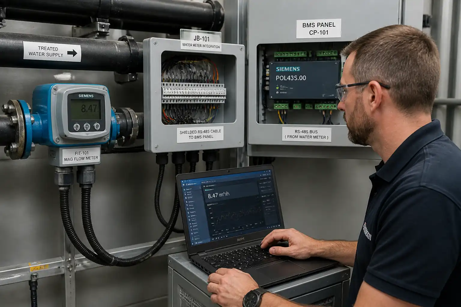
This Method Statement covers end-to-end integration of mechanical water meters with the Building Management System (BMS) for potable, grey, irrigation, and make-up water services. It includes meter identification, pulse or communication output wiring, BMS point mapping, consumption verification, trend logging setup, coordination with plumbing activities, QA/QC inspections, and final handover records.
Included Activities
- Verification of approved submittals, drawings, I/O schedules, and network architecture.
- Identification and tagging of water meters; confirmation of output type (pulse dry contact/NPN/PNP, M‑Bus, Modbus RTU/TCP, BACnet MS/TP/IP).
- Supply/installation of signal cables, junction boxes, labels, interface/isolator modules, M‑Bus level converters, RS‑485 terminations, and surge protection as required.
- Wiring, termination, shielding/earthing, and segregation of ELV cabling.
- BMS controller/database configuration, point naming, units, scaling, rollover handling, and polling/trending strategy.
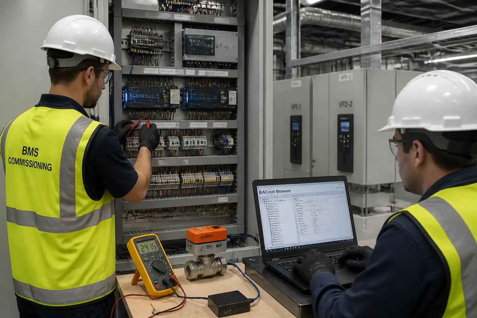
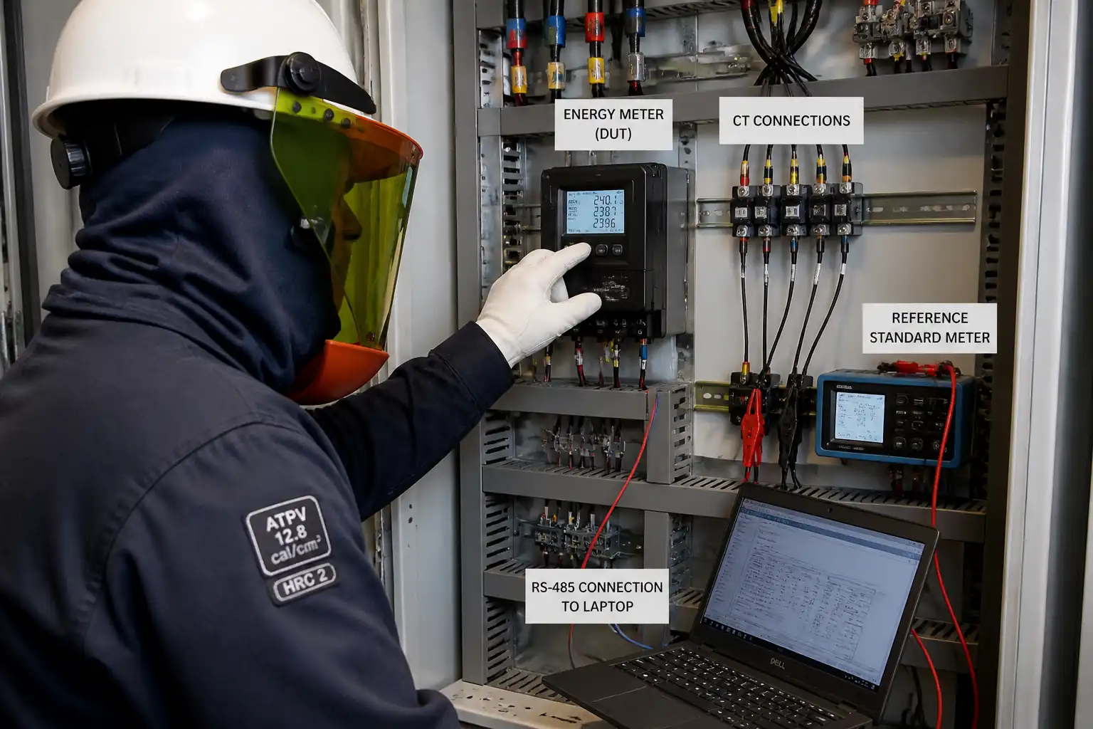
- Functional testing: continuity, insulation (as applicable), protocol validation, pulse verification using simulator and controlled flow, comparison with meter register, alarms, and data integrity.
- Coordination with plumbing for flow provision, isolation/bypass use, and leak/zero-flow tests.
- Documentation: redlines/as-builts, test sheets, trend exports, training, and handover.
Exclusions
- Supply/installation of the water meters themselves (by Plumbing Contractor unless stated).
- Permanent civil/architectural penetrations and firestopping (by others unless agreed).
- IT network core switches/NTP services (by ICT unless specified).
Constraints
- Works on live systems require permits and shut-down coordination.
- Communications parameters and pulse values must match manufacturer data and project specifications [Verify per project specifications].
- All works to comply with referenced standards and local regulations [Verify per project HSE plan and local regulations].
Acceptance Summary (high-level)
- Correct wiring/terminations, compliant segregation, and labeling (100% inspected).
- Successful communication or pulse counting with accuracy within ±1% of meter register over test volume or within meter resolution, whichever is greater [Verify per project specifications].
- Trend logs enabled with agreed interval (typ. 15 min) and retention (≥13 months) [Verify per project specifications].
- Complete handover dossier with approved as-builts and test records.
References
| Document Type | Reference / Number | Revision | Notes |
|---|---|---|---|
| Standard | ISO 4064 / OIML R49 | Use project-approved meter make/model. | |
| Standard | ASHRAE 135 (BACnet) | ||
| Standard | Modbus Application Protocol Specification | RTU over RS‑485; TCP over Ethernet. | |
| Standard | EN 13757 (M‑Bus) | ||
| Standard | IEC 60364 / BS 7671 / NFPA 70 (NEC) [Verify per project] | ||
| Standard | IEC 60529 (IP ratings) | ||
| Standard | IEC 61000 series [Verify parts per equipment] | ||
| Standard | TIA/EIA‑568 [if Ethernet used] | ||
| Standard | ISO 50001 (guidance) | For policy alignment. |
Responsibilities
| Role | Responsibility | Name / Party |
|---|---|---|
| Coordinator | Main Contractor / MEP Coordinator | Main Contractor |
| BMS Engineer | BMS Subcontractor | BMS Subcontractor |
| Plumbing Supervisor | Plumbing Subcontractor | Plumbing Subcontractor |
| ELV Supervisor | Electrical/ELV Subcontractor | Electrical Subcontractor |
| QA/QC | QA/QC Engineer | Main Contractor |
| HSE | HSE Officer | Main Contractor |
| Engineer | Client/Consultant | Consultant |
Resources
| Resource Type | Description | Quantity | Remarks |
|---|---|---|---|
| Manpower | Database configuration, mapping, testing | 1–2 [Verify per project] | |
| Manpower | Cabling, termination, labeling | 2–4 [Verify per project] | |
| Manpower | Arrange flows for tests | 1–2 | |
| Manpower | Hold/witness points | 1 |
Materials
| Material | Specification / Grade | Quantity | Remarks |
|---|---|---|---|
| Shielded pair cable | IEC 60332-1, LSZH | ||
| RS‑485 data cable | Impedance 120 Ω ±10% | ||
| M‑Bus cable | EN 13757 compliant | ||
| Cat6 cable & RJ45 | Cat6, 250 MHz | ||
| Enclosures | IEC 60529 IP65/66 | ||
| Signal interface | Input per meter output; 24 VDC typ. | ||
| Resistors | 1/4 W min | ||
| Label sets | Mechanical & UV resistant |
Equipment
| Equipment | Capacity / Type | Quantity | Inspection Required |
|---|---|---|---|
| DMM | 1–2 | ||
| Megger | 1 | ||
| Scope/logger | 1 | ||
| Commissioning laptop | 1 | ||
| Calibrator | 1 | ||
| Portable ultrasonic | 1 | ||
| LOTO, ladders | As required |
Prerequisites
- Approved shop drawings, schematics, I/O schedules, network diagrams, and vendor datasheets for meters and BMS controllers.
- Approved material submittals for cables, junction boxes, isolators, terminations, and labeling.
- Confirmed meter output type and settings: pulse value (e.g., 1 pulse = 1/10/100 L), minimum pulse width, contact type; or protocol (M‑Bus baud, primary/secondary address; Modbus slave ID, baud/parity; BACnet device instance/MAC/baud). [Verify per manufacturer]
- Power availability to BMS panels, controllers, and M‑Bus masters/converters. UPS status verified if applicable.
- Permits/authorizations: LOTO for electrical panels, confined space (if meter in pit), work-at-height, and any shutdown notices [Verify per project HSE plan and local regulations].
- Coordination with Plumbing for test windows, bypass/isolations, drain points, and safe discharge arrangements.
- BMS server and network reachable; time synchronization source (NTP) defined; user accounts/roles prepared.
- Calibrated test equipment certificates current (within 12 months or per QA plan).
- Toolbox Talk (TBT) conducted; inspections and hold/witness points agreed with Consultant.
Method Sequence
| Step | Activity | Description | Responsibility | Inspection / Hold Point |
|---|---|---|---|---|
| 1 | Site Survey & Meter Identification | Confirm meter locations vs drawings; record meter make/model/serial, line size, service, and output type. Affix durable meter tag with unique ID. Photograph installation. | BMS/Plumbing | Visual |
| 2 | Cable Routing & Segregation | Install trays/conduits; route signal cables with min. separation from LV power (typ. ≥150 mm parallel; cross at 90°) [Verify per project]. Avoid sources of EMI; use IP65 boxes in wet areas. | ELV | In-process |
| 3 | Termination & Shielding | Terminate at meter JB and BMS panel per schematics. For RS‑485: daisy-chain topology, 120 Ω termination at both ends, single-point shield ground at controller. For pulse: connect via isolator/debounce module if required. | ELV/BMS | Visual |
| 4 | Pre-Connection Cable Tests | Before connecting to meter/device, test continuity and insulation between conductors and to earth. Do not megger across meter contacts/electronics. | ELV | Test |
| 5 | Controller & Network Configuration | Set controller addresses, baud, bias; add devices (M‑Bus/Modbus/BACnet). Configure object/point names per naming convention; engineering units (L, m³, L/s); scaling; rollover logic (32‑bit). | BMS | Desktop review |
| 6 | Pulse Input Calibration | Set counter mode (rising edge), debounce/filter (typ. 20–200 ms [Verify]), minimum pulse width (typ. ≥30 ms [Verify]); enter pulse value (e.g., 1 pulse = 10 L) per meter plate. | BMS | Parameter check |
| 7 | Protocol Mapping (Comms Meters) | Import device map; verify registers/OBIS codes. Modbus: confirm function codes, byte order, float scaling. BACnet: confirm object types/instances. M‑Bus: verify primary/secondary address and medium type. | BMS | Bench/live test |
| 8 | Functional Flow Test (On Meter) | With Plumbing, establish controlled flow. Record start register and BMS reading. Pass defined volume (e.g., 100–1,000 L for small meters; 1–5 m³ for large mains) [Verify]. Compare totals. | BMS/Plumbing | Witness |
| 9 | Zero-Flow & Leak Detection Logic | With valves closed, verify zero-flow; configure leak alarms (e.g., continuous flow > preset for >x minutes overnight) [Verify]. | BMS/Plumbing | Witness |
| 10 | Trend Logging & Dashboards | Configure trend intervals (typ. 15 min; leak diagnostics 5 min) and retention (≥13 months) [Verify]. Create daily/weekly/monthly consumption reports and graphics. | BMS | Desktop |
| 11 | 72‑Hour Stability Run | Leave system logging for ≥72 hours under normal operation. Review comms errors, missing data, drift. | BMS | Review |
| 12 | Documentation & Handover | Submit as-builts, point list, addressing, trend/alarm configs, test sheets, O&M, training records, warranties. | BMS/Main Contractor | Document review |
Health, Safety, and Environment (HSE) – Task-Specific Safety Controls
Key Hazards and Controls
- Hazard: Work on or near live ELV/LV panels
- Likely consequence: Electric shock, burns
- Engineering/procedural control: Implement LOTO; isolate and prove dead using approved tester; use 24 VDC for interfaces where feasible; install finger-safe terminals; segregate from energized components.
- Required PPE: Electrically rated gloves, safety glasses, FR clothing as required, insulated tools
- Collective preventive measure: Barriers and lockable panel doors; signage; keep non-essential personnel out
-
Inspection/permit/supervision: Electrical PTW/LOTO log; Supervisor sign-off; periodic HSE audits [Verify per project HSE plan and local regulations]
-
Hazard: Working at height for cable routing/labeling
- Likely consequence: Falls, fractures
- Engineering/procedural control: Use inspected podium steps or mobile tower; maintain 3-point contact; no improvised platforms; secure tools.
- Required PPE: Hard hat, safety shoes, harness if required by risk assessment
- Collective preventive measure: Exclusion zone; edge protection where applicable
-
Inspection/permit/supervision: Equipment inspection tags; WAH permit; competent person oversight
-
Hazard: Confined spaces (meter pits/plant rooms with poor ventilation)
- Likely consequence: Asphyxiation, entrapment
- Engineering/procedural control: Confined space assessment; gas test; standby attendant; retrieval plan; continuous communication
- Required PPE: Gas detector, harness with lifeline as applicable, headlamp
- Collective preventive measure: Ventilation and access control
-
Inspection/permit/supervision: Confined space permit; trained entrants and attendant
-
Hazard: Water discharge during tests (slip hazard, property damage)
- Likely consequence: Slips, equipment damage
- Engineering/procedural control: Use planned drains/hoses to safe discharge; deploy drip trays and absorbents; keep electrical equipment elevated
- Required PPE: Slip-resistant footwear, gloves
- Collective preventive measure: Floor signage and barriers, housekeeping
-
Inspection/permit/supervision: Supervisor to approve discharge route; daily HSE inspection
-
Hazard: Drilling/punching for glands in panels or boxes
- Likely consequence: Eye injury, lacerations, metal swarf causing shorts
- Engineering/procedural control: Remove/cover internal components; use swarf-catch mats; deburr and clean; use correct gland sizes with IP seals
- Required PPE: Safety glasses/face shield, gloves
- Collective preventive measure: Local extraction or wet swarf control; housekeeping
-
Inspection/permit/supervision: Hot-work permit if sparks; tool inspection
-
Hazard: Manual handling of spools, enclosures, and access equipment
- Likely consequence: Strains, sprains
- Engineering/procedural control: Team lifts; use trolleys; follow weight limits
- Required PPE: Gloves, safety shoes
- Collective preventive measure: Mechanical aids
-
Inspection/permit/supervision: Manual handling training; supervisor briefing
-
Hazard: Exposure to biohazards (stagnant water, aerosols)
- Likely consequence: Illness, dermatitis
- Engineering/procedural control: Avoid spraying; flush systems per plumbing method; hygiene practices
- Required PPE: Gloves, eye protection
- Collective preventive measure: Hand-wash station availability
-
Inspection/permit/supervision: HSE hygiene guidance reviewed
-
Hazard: Noise and vibration from nearby plant
- Likely consequence: Hearing damage
- Engineering/procedural control: Schedule during low-noise periods; limit exposure duration
- Required PPE: Hearing protection if levels >85 dB(A)
- Collective preventive measure: Barriers/signage
-
Inspection/permit/supervision: Spot noise checks; HSE monitoring
-
Hazard: Network security changes (connecting devices to enterprise LAN)
- Likely consequence: Cybersecurity breach impacting building systems
- Engineering/procedural control: Follow ICT change control; use approved VLANs and credentials; disable default passwords; role-based access
- Required PPE: N/A
- Collective preventive measure: Network access control
- Inspection/permit/supervision: ICT approval tickets; security audit logs
Emergency Preparedness
- Spill kits and absorbents available for unintended water release.
- First aid kit on site; trained first aider identified.
- Emergency shutdown and contact list posted at work area.
Environmental Controls
- Water discharge control: Route test water to approved drains; no discharge to ground or sensitive areas; use hoses and backflow-preventers as required [Verify per local code].
- Waste management: Collect cable offcuts, insulation, packaging; segregate and dispose via approved recyclers. Treat e-waste (failed modules, boards) as hazardous per local rules.
- Noise/dust: Limit drilling time windows; use low-dust techniques; vacuum swarf and debris.
- Energy and data efficiency: Set polling intervals to the minimum necessary to meet monitoring objectives (typ. 15–60 s) to reduce network/CPU load; trend interval optimized (typ. 15 min).
- Chemical use: Avoid solvent cleaners near potable water components; use approved, biodegradable cleaners where required.
- Leak prevention: Inspect all JBs/glands for IP integrity; use drip loops on cables in wet zones.
- Environmental incidents: Report and record any spills/discharges; implement corrective actions per project environmental plan.
QA/QC
QA/QC Strategy
- 100% inspection of terminations, labels, and cable routes before concealment.
- Hold Points (H): Before cable concealment; before energization/connection to meters; functional accuracy test; final handover review.
- Witness Points (W): Meter identification; parameter configuration; trend/alarm setup; 72‑hour stability review.
Test Instruments
- Use calibrated instruments; record serial numbers and calibration due dates on test sheets.
Documentation Control
- Maintain drawing register and redline updates daily; as-builts to reflect device addresses, cable IDs, termination details, and network topology.
Sampling and Re‑tests
- Continuity/insulation: 100% of cables pre-connection; re-test any repaired cable segment.
- Functional tests: 100% of meters integrated.
- If failure occurs, implement root cause analysis and corrective action; repeat test until acceptance.
Acceptance Metrics
- Wiring: Correct core identification, ferrules, torque within vendor limits.
- Communication: Stable with error rate <1% over 30 minutes [Verify per vendor/spec].
- Pulse accuracy: BMS count within ±1% of meter register or within meter resolution.
- Data integrity: No gaps >1 trend interval during 72‑hour run; NTP time aligned within ±2 s [Verify].
Attachments
- Approved shop drawings, schematics, and network topology (latest revision).
- Meter schedule with IDs, locations, outputs, and pulse values/protocol addresses.
- Cable routing layouts and tray/conduit details.
- BMS point list with naming conventions, units, scaling, rollover notes.
- Trend and alarm configuration printouts.
- Test records: continuity/insulation, pulse simulator, functional flow accuracy, zero-flow, 72‑hour stability.
- Calibration certificates for test equipment.
- O&M manuals and data sheets for meters, isolators, converters, and controllers.
- As-built drawings (redlines incorporated) and termination details.
- Training attendance and content outline.
- Warranties and spare parts list.
This content is a read-only public reference. Download or customize to get an editable version.
ITP preview
The first inspection activities from the linked ITP for Method Statement: Water Meter Integration with Building Management System (BMS):
| Activity | Inspection / Test | Acceptance Criteria | Responsibility | Record |
|---|---|---|---|---|
| Material Submittals Approval | Review datasheets for cables, JBs, isolators, converters | Compliant with specs/standards; approvals received | QA/QC, Consultant | Approved submittals, MIRs |
| Meter Verification & Tagging | Check meter make/model/serial, output type, location; apply tags | Matches approved schedule; unique IDs; photos recorded | BMS/Plumbing, QA/QC | Meter register, photos |
| Cable Routing & Segregation Inspection | Visual inspection before concealment | Separation maintained; fixings correct; bends within limits; IP maintained | ELV, QA/QC, Consultant | IR, inspection checklist, photos |
Showing 3 of 13 inspection activities. View full ITP →
Related Inspection and Test Plan
An Inspection and Test Plan (ITP) is available for Method Statement: Water Meter Integration with Building Management System (BMS). The ITP defines the inspection activities, acceptance criteria, hold and witness points, responsible parties, and records required to verify the work described in this method statement.
View the Method Statement: Water Meter Integration with Building Management System (BMS) ITP →Frequently asked questions
Continue with related Quollnet resources connected to this method statement.