
Inspection and Test Plan for Method Statement – Building Management System (BMS) Testing & Commissioning
AI-assisted inspection and test plan connected to a method statement, with PDF and Excel export.
More than a static template
Unlike a downloadable Word or PDF template, this ITP is an AI-assisted editable starting point directly connected to its method statement. Every inspection activity, hold point, and acceptance criterion is structured and ready to adapt to your project.
- AI-assisted customization — Tailor inspection activities and acceptance criteria to your specific project scope.
- Linked method statement — This ITP is connected to the corresponding method statement describing the work sequence.
- Multiple export formats — Download as a formatted PDF or editable Excel spreadsheet.
- Editable starting point, not a final document — Review and verify all content against your project specifications and standards before use.
What you can customize
When you save this ITP to your account, every inspection row becomes editable. You can add, remove, or modify:
- Inspection activity — Description of what is being inspected.
- Inspection type — Hold point (H), Witness point (W), Review (R), or Monitor (M).
- Responsibility — Contractor, subcontractor, engineer, or client.
- Frequency — How often the inspection occurs.
- Acceptance criteria — Referenced standard or specification requirement.
- Records — Forms, test reports, or checklists required as evidence.
Why this ITP is used
To ensure all BMS components and integrated systems are verified against specifications through hold/witness points and objective acceptance criteria.
Who uses this inspection and test plan
Commissioning managers, BMS engineers, MEP contractors, Consultants/Employer’s Representatives, and IT/OT specialists.
When this ITP is prepared and submitted
From pre-commissioning through functional performance testing to final handover and training.
Who receives or approves this ITP
Consultant/Employer’s Representative for review and witnessing.
Inspection scope
Covers installation readiness, energization, configuration, I/O tests, graphics, alarms, trends, schedules, functional tests, integrations, failover, and documentation.
Typical hold, witness, and review points
Hold: Installation readiness, key FPTs (AHUs, chiller/boiler plants), third‑party cause/effect, final handover. Witness: Panel energization, graphics/alarm/trend checks, terminal unit FPT sampling, failover tests.
Typical inspection records
PFC and FPT sheets, I/O test records, calibration certificates, network scans, screenshots, trend exports, interface mapping, sign-offs, training logs.
Important approval note
This ITP is an AI-assisted editable starting point, not a pre-approved document. Before use on any project, all inspection activities, hold points, and acceptance criteria must be reviewed and approved by the relevant parties (superintendent, principal contractor, or client representative) in accordance with your contract and project quality plan.
Always verify acceptance criteria against your applicable drawings, specifications, and regulatory requirements. Hold points must be confirmed with the relevant authority before work proceeds past that point.
Inspection and test plan
| Activity | Inspection / Test | Acceptance Criteria | Responsibility | Record |
|---|---|---|---|---|
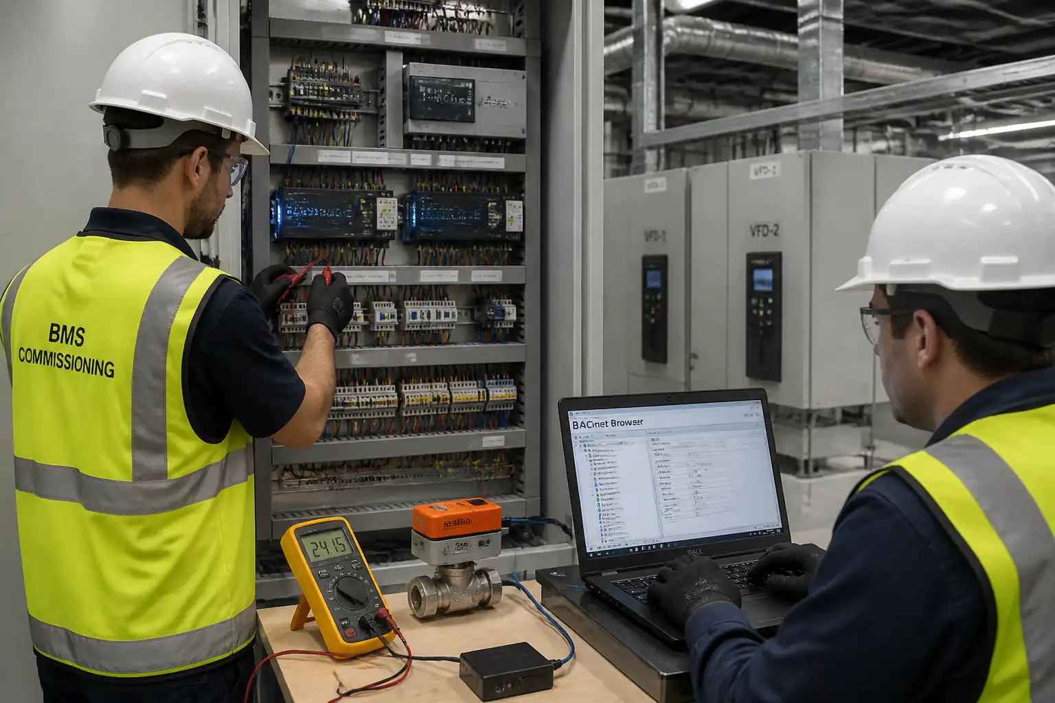
| Installation Readiness (PFC) | Visual, torque sampling, IR/continuity, RS‑485 termination check | Zero critical defects; IR ≥ specified; correct segregation/earthing; labels complete [Verify] | BMS Lead / Electrical Engineer / Consultant (Witness) | PFC checklist; photos; IR test sheets |
| Panel Energization | Voltage measurement; functional indicators; thermal scan (if available) | Correct voltage within tolerance; no trips/abnormalities after 15 min | Electrical Engineer / Consultant (Witness) | Energization record |
| Controller Configuration & Network Verification | BACnet/IP & MS/TP scan; device instance/IP uniqueness; NTP sync | Unique IDs; stable token; time sync ±1 min; network utilization <60% [Verify] | BMS Lead / IT/OT Engineer | Network scan; IP plan; time sync log |
| I/O Point-to-Point – DI/DO | Simulate each DI/DO; verify at head-end | 100% correct state/command; correct fail-safe behavior | Controls Technicians / Consultant (Witness) | I/O sheets signed |
| Analog Inputs Calibration | Loop simulation and field probe comparison | Temp ±0.5–1.0 °C; RH ±3%; DP ±1% FS or ±5 Pa [Verify] | Controls Technicians | Calibration certificates; AI sheets |
| Actuator/Valve Functional Test | 0–100% stroke; feedback scaling; valve close-off | Feedback ±5%; correct direction; no hunting/leakage | Controls + Mechanical | Actuator test sheets |
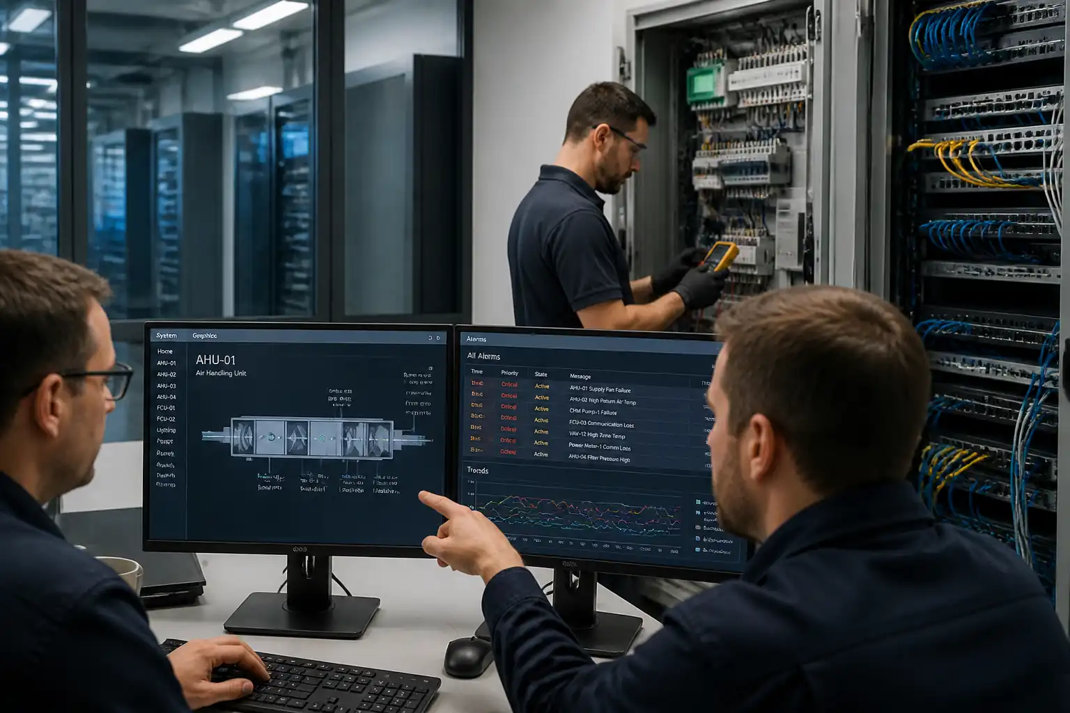
| Graphics & Naming Verification | Binding checks; page review | 100% points present; consistent naming; no broken links | BMS Lead / Consultant (Witness) | Graphics verification checklist; screenshots |
| Alarm Strategy Testing | Trigger alarms; route to recipients; ack/escalate | Critical ≤5 s; non-critical ≤60 s; audit trail recorded | BMS Lead / Consultant (Witness) | Alarm test log; screen captures |
| Trend Logs Setup & Verification | Sampling, retention, export | Intervals per spec; retention ≥13 months; successful export | BMS Lead / Server Admin | Trend config list; CSV samples |
| Schedules & Time Functions | Weekly/holiday schedules; DST change | Switching ±1 min; override timers logged | BMS Lead | Schedule test records |
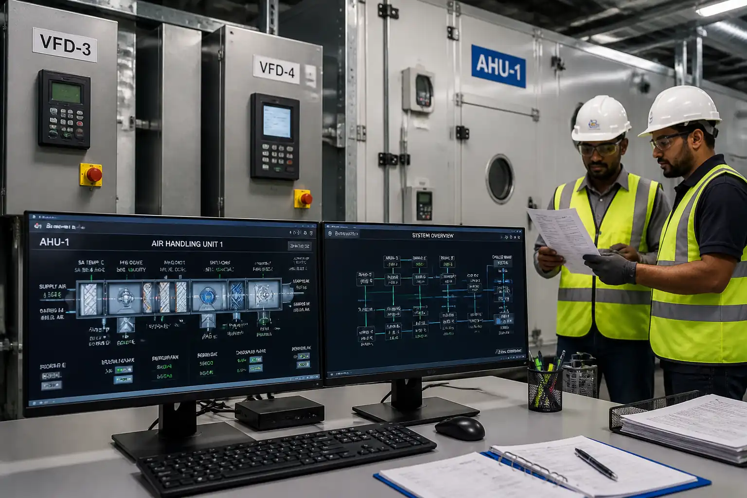
| FPT – AHUs/FAHUs | Start/stop; PID; safeties; fire trip | Supply air temp ±0.5 °C; static ±50 Pa; stable response; shut-down on trip | BMS + Mechanical / Consultant (Hold) | FPT sheets; trend plots; sign-off |
| FPT – Terminal Units (VAV/FCU) | Airflow/temperature control; occupancy logic | Airflow ±10%; zone temp ±1.0 °C steady-state [Verify] | BMS + Mechanical / Consultant (Witness) | FPT sheets; TAB extracts |
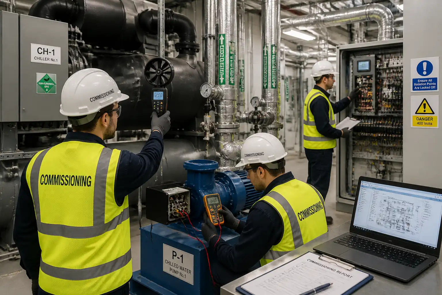
| FPT – Chiller/Boiler Plant & Pumps | Lead/lag; ΔT optimization; pump VFD; failover | Auto changeover; ΔT within design ±1.5 °C; restart <5–10 min [Verify] | BMS + OEM / Consultant (Hold) | FPT sheets; OEM sign-off; trends |
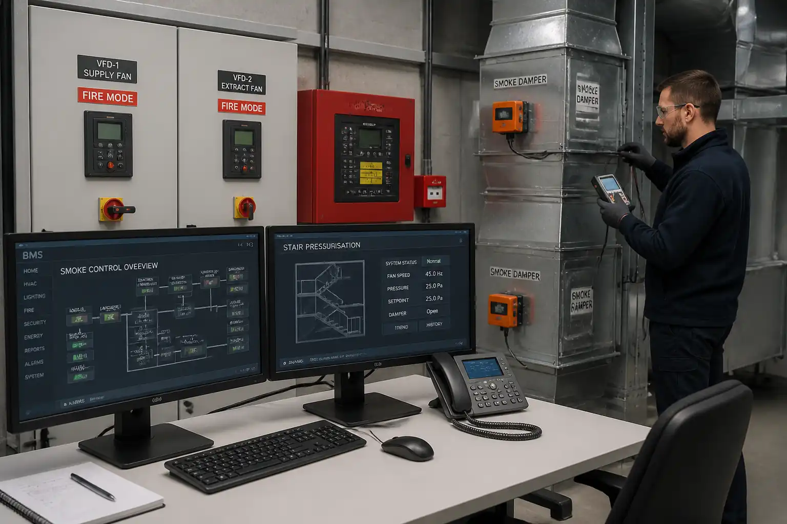
| Third-Party Interface & Cause/Effect | BACnet/Modbus read/write; FAS trips; meters | 100% mapped; cause/effect executed; scaling correct | BMS + Relevant Vendors / Consultant (Hold) | Interface test sheets; mapping lists |
| Failover & Backup/Restore | UPS autonomy; DB restore; controller restart | No data loss; successful restore; auto-recovery <10 min | BMS + IT/OT / Consultant (Witness) | Failover report; backup logs |
| Training & Handover Dossier | Attendance; competency Q&A; document review | All deliverables submitted and accepted; training completed | BMS / Main Contractor / Consultant (Witness) | Training log; handover certificate; deliverable index |
This table is a read-only public reference. Download the PDF or Excel version, or customize this ITP to edit it for your project.
Frequently asked questions
Related method statement
This Inspection and Test Plan is associated with the Method Statement – Building Management System (BMS) Testing & Commissioning method statement, which describes the step-by-step construction sequence, resources, materials, equipment, safety controls, and environmental controls for this activity.
View the Method Statement – Building Management System (BMS) Testing & Commissioning method statement →Continue with related inspection, method statement, article, and checklist resources.